
Фотографии

-

Регистрационный номер: G-ALCV [5], VZ724 [5] Rotary-wing Cerberus - the Air Horse remains the only helicopter to fly with three rotor-heads. The prototype, VZ724, is seen here during one of the public displays it made after its first free flight on December 8, 1948. Note the open door to aid cooling of the single horizontally-mounted Merlin engine
Самолёты на фотографии: Cierva W.11 Air Horse - Великобритания - 1948
-

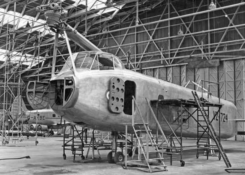
Регистрационный номер: G-AKBE, G-ALCV [5], VZ724 [5] With the second of the two Cunliffe-Owen Concordias, G-AKBE, in the background, work progresses on the first W.11 Air Horse prototype, VZ724, at Eastleigh in the spring of 1949. The extreme nose of the Air Horse’s fuselage could be opened, as seen here, to give access to the rear of the instrument panel and pilot’s controls.
Самолёты на фотографии: Cierva W.11 Air Horse - Великобритания - 1948Cunliffe-Owen Concordia - Великобритания - 1947
-
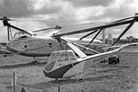
Регистрационный номер: G-AJCJ, G-ALCV [5], VZ724 [5] Little and large - another photograph of the prototype Air Horse at the 1948 SBAC show, alongside G-AJCJ, the prototype of its diminutive stablemate, the Cierva W.14 Skeeter, which made the type’s maiden flight at Eastleigh the following month. The Skeeter went on to be developed and built in numbers by Saunders-Roe.
Самолёты на фотографии: Cierva W.11 Air Horse - Великобритания - 1948Cierva/Saunders-Roe W.14 Skeeter - Великобритания - 1948
-

Регистрационный номер: G-ALCV [5], VZ724 [5] The first Air Horse, VZ724, made its public debut at the 1948 SBAC show at Farnborough that September, a month before it began its ground running and tethered hovering trials, and three months before its first free flight. Fitted with its original small fins, it wears its civil registration, G-ALCV, allocated during August-October 1948.
Самолёты на фотографии: Cierva W.11 Air Horse - Великобритания - 1948
-

Регистрационный номер: G-ALCV [5], VZ724 [5] By this time fitted with fins of increased area, VZ724 clatters overhead during a flight in 1949, possibly at that year’s SBAC show, at which it performed a memorable flying display. The fins never incorporated rudders, yaw control being effected by means of fore-and-aft cyclic-pitch variation applied differentially to the rear rotors.
Самолёты на фотографии: Cierva W.11 Air Horse - Великобритания - 1948
-

Before the Air Horse came the ‘‘Spraying Mantis”, a full-size mock-up of which is seen here at Eastleigh in the summer of 1946. The design, intended for agricultural work (note the large hopper for insecticide aft of the engine), incorporated forward-projecting booms with a rotor-head on each and a smaller rotor on the tailboom.
Самолёты на фотографии: Cierva W.11 Air Horse - Великобритания - 1948
-

LEFT Accompanying the RAE’s Structures Accident Note were a number of photographs and illustrations of the relevant parts, including this photograph showing the fractured front rotor swashplate spindle (bottom), alongside the (slightly bent) starboard spindle (middle) and port spindle still attached to one arm of the scissor link.
RIGHT The fracture surface from head-on. Failure had occurred at the change of section from 0-8in (20mm)-diameter to 0-5in (12-7mm)-diameter, and had originated by the initiation of fatigue cracks at diametrically opposite sides, as denoted by arrows “A” and “B” (essentially perpendicular).Самолёты на фотографии: Cierva W.11 Air Horse - Великобритания - 1948
-

Also attached to the RAE’s Structures Accident Note No 228 was Figure 1, a large fold-out detailing the Air Horse’s rotor-head and exactly where and how the critical spindle had failed. The report concluded that “failure of the front rotor swashplate-driving spindle had occurred through fatigue caused through alternating bending in the plane of rotation of the swashplate assembly”.
Самолёты на фотографии: Cierva W.11 Air Horse - Великобритания - 1948
-

Technical illustrator J.H. Clark provided this fine drawing of the Air Horse’s rotor-head for the April 6, 1949, issue of The Aeroplane. We have added a blue circle to show the area of the failure which caused the crash.
Самолёты на фотографии: Cierva W.11 Air Horse - Великобритания - 1948
-

Various powerplants were considered for the Air Horse, redesignated W.11T, including a pair of Armstrong Siddeley Mambas (featuring the use of auxiliary propellers for use in forward flight) or two Rolls-Royce Dart turbines or Merlin piston engines, the latter as seen here.
Самолёты на фотографии: Cierva W.11 Air Horse - Великобритания - 1948


Статьи
- -
- ??? - Mad dogs & englishmen
- A.Arthy - Two days in February (1)
- B.Taghvaee - The shah's Jetstars
- C.Gibson - Hawker's Star Destroyer
- F.Villeneuve - Hawk One (2)
- G.Baughen - 1940. The battle of ... Kent?
- J.-C.Carbonel - France's Air Pioneers: Louis Bleriot
- J.Forsgren - Sweden's parasol fighters
- K.Hayward - Shorts: The perennial thorn
- M.Wickstead - Italy's forgotten airlines (2)
- N.Stroud - Tuesday the 13th
- P.Davidson - Off the Beaten Track...
- P.Hobbins - Flying the "Bathfire"
- T.Buttler - Heinkel's last fighter