

Flight, April 1931
THE PARNALL PARASOL MONOPLANE
This "Flying Laboratory" has been designed for making full-scale tests of wings. The parasol wing is so attached to the fuselage that it is free to move slightly, and a dynamometer is incorporated by means of which the forces on the wing can be ascertained.
IN spite of such modern aids to research as compressed-air wind tunnels, and a knowledge of modern aerodynamic vortex theory, there are still problems to be solved which require accurate full-scale test results. "Scale effect" appears capable of determination in high-density wind tunnels such as have been used in the United States for several years and are now being installed in this country, but there is little doubt that many features of a wing, such as its behavior at the stall, whether or not it has a tendency to "flick" into a spin, and so forth, are better investigated in actual full-scale flight. It may be recollected by some of our readers that several rears ago the American National Advisory Committee for Aeronautics made an attempt to test wings by towing large-scale models in an inverted position, some distance below an aeroplane. Fairly good results were, we believe, obtained in this way, but the system does not appear to have come into general use, and so presumably there were "snags" in it. Recently, George Parnall & Company, of Yate, Gloucestershire, built for the British Air Ministry, two parasol monoplanes in which the wing mounting was so designed that the wing could be made free to move slightly in relation to the fuselage, the movement being restricted to small limits and a dynamometer incorporated in the wing-supporting system so that the forces on the wing could be measured at any angle of incidence. The Air Ministry has now very kindly agreed to a brief description of the Parnall Parasol Monoplane being published, and moreover, the Parnall Company is at liberty to sell machines of this type to anyone at home or abroad who may desire to operate such a flying laboratory.
In our issue of April 3 we referred briefly to the Parnall Parasol Monoplane used for research into the aerodynamic forces on the wings. This machine is of composite construction, wood entering largely into the scheme, but high-tensile steel tubing being used for the swinging cradle on which the wing is supported and for the outboard wing-bracing struts.
In aerodynamic design, the Parnall Parasol Monoplane is notable for its clean lines, these being essential in a machine of this type, in which interference with the free flow over the wing must be kept down to a minimum. The fuselage, of normal wood girder type as regards its main structure, has been carefully streamlined by fairings, these fairings being easily detachable in order to facilitate inspection of the interior and adjustment of the wing-supporting structure.
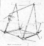
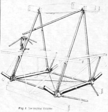
It will be noted that the parasol wing is supported on its centre line by two inverted Vees of steel tube, hinged to the top longerons of the fuselage, and outboard by parallel struts attached by pivot joints to the lower longerons via adjustable members. The supporting structure forms, in fact, a deformable parallellogram, the amount of deformation permitted being limited by yet another member which is linked with the dynamometer. This member slopes downward and forward from the rear spar to a crank under the fuselage deck. This crank is, in turn, connected to the dynamometer by a horizontal fore-and-aft tube. The degree of free movement permitted to the wing is provided in this link between the crank and the dynamometer. The general scheme of the cradle suspension of the wing is indicated in the perspective diagrammatic sketch. Fig. 1.
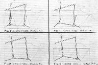
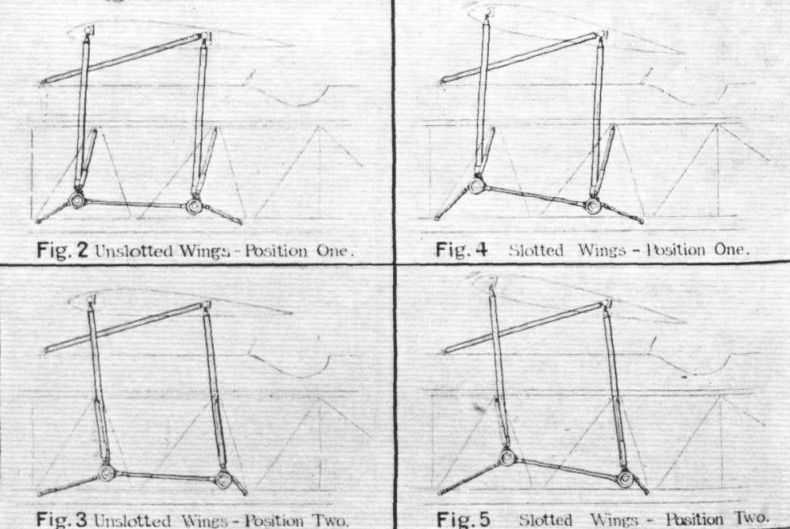
The reading obtained on the dynamometer from one setting of the wing determines the magnitude of the air force on the wing, but not its direction. To obtain this, and from it the components of lift and drag, a second reading is necessary. This is obtained by altering the points of attachment of the wing bracing struts on the fuselage. The way in which this is done is illustrated diagrammatically in Figs. 1, 2, and 3. Although two positions only are necessary, three positions have actually been provided in order to afford a check reading.
Certain wings, and in particular wings fitted with slots or other artificial aids to high lift, require the forces to be measured up to quite high angles of incidence. To enable this to be done an alternative series of wing attachment positions has been provided. These are shown diagrammatically in Figs. 4 and 5. All these changes in the positions of the strut attachments can be easily and quickly carried out with the form of structure used in the Parnall Parasol Monoplane.
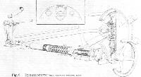
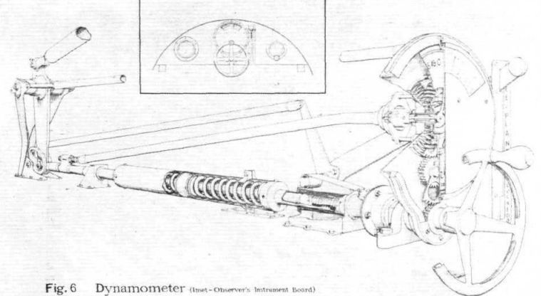
The mechanism of the dynamometer is illustrated in the part-sectioned perspective view, Fig. 6. This sketch is self-explanatory, but attention should, perhaps, be drawn to the method adopted for limiting the movement of the wing. The lower end of the dynamometer has two rollers, one on each side, constrained by quadrant-shape cams. These cams can be rotated through approximately 90 degrees by a lever in the pilot's cockpit. The width of the cams varies along the length, one end fitting the roller, while the other end has a maximum clearance of 6 millimetres. This, therefore, represents the amount of "play" of the wing, and is sufficient to get a reading, while at the same time failure of any part of the dynamometer mechanism will not affect the safety of the machine in any way.
The control of the dynamometer is in the front cockpit, which is occupied by the observer, In the pilot's cockpit there is, in addition to the usual equipment, a lever which actuates a hydraulic brake on the airscrew. By means of this brake the engine can be stopped and the dynamometer readings taken while the machine is in gliding flight, i.e., without the complications resulting from having a portion of the wing in the slipstream. An R.A.E. Gas Starter, Mark II, is fitted by means of which the engine can be started again when the glide has been completed.
The engine fitted in the Parnall Parasol Monoplane is an Armstrong-Siddeley "Lynx" Mark IV, which is supercharged to an altitude of 4,400 metres (14,500 ft.). Normally the dynamometer readings are taken at 2,400 metres (7,875 ft.) for which altitude the airscrew has been designed.
The main dimensions of the Parnall Parasol Monoplane are as follows: Length o.a., 30 ft. 4 in. (9-25 m.); wing span, 42 ft. (12-80 m.); wing area, 294 sq. ft. (27-33 sq. m.). The weight of the machine empty is 2,220 lb. (1,010 kg.) and the total loaded weight 2,870 lb. (1,304 kg.). At the operational height of 8,000 ft. the maximum speed is 119 m.p.h. (191 km/h), and the stalling speed, 56-5 m.p.h. (91 km/h). The rate of climb is 750 ft./min. (3-82 metres per second). The climb to 8,000 ft. (2,400 metres) takes 12-4 minutes. The absolute ceiling is 29,000 ft. (8,900 metres).
These figures refer to the machine as fitted with the wing tested by the Air Ministry. When a different wing is used, the figures will, of course, be influenced by the characteristics of that particular wing.
Anyone seriously interested in the Parnall Parasol Monoplane may obtain further particulars direct from the makers, George Parnall & Company, Yate Aerodrome, Gloucestershire, England.
- Flight, April 1931
THE PARNALL PARASOL MONOPLANE
Фотографии

-
Flight 1931-04 / Flight
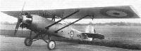
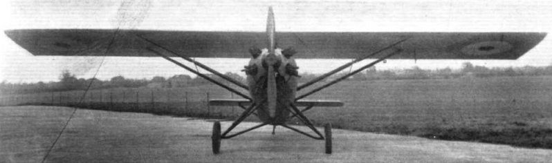
Регистрационный номер: K1228 [4] THE PARNALL PARASOL MONOPLANE: The wing is raised well clear of the fuselage to avoid interference.
-
Flight 1931-04 / Flight
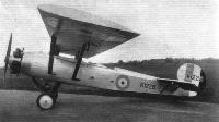
Регистрационный номер: K1228 [4] Side View of the Parnall Parasol Monoplane. The wing bracing struts are in the form of a deformable parallelogram.
-
Flight 1935-11 / Flight
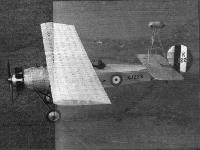
Регистрационный номер: K1228 [4] Studying air flow: The Parnall parasol monoplane used at the Royal Aircraft Establishment for filming, by an automatic camera, the movements of wool tufts on the wing. The actual air forces on the wing are also measured.
-
Air Enthusiast 2003-01 / K.Wixey - The Bolas touch
Регистрационный номер: K1228 [4] High-wing monoplane, a two-seat experimental and research aircraft for testing various wing incidences, slots and high-lift aids, powered by a 226hp (168kW) Armstrong Siddeley Lynx IV seven-cylinder supercharged radial. Two built, K1228 (illustrated) and K1229.
-

-
Flight 1931-04 / Flight
Fig.1. Swinging Frame
-
-
Flight 1931-04 / Flight
Fig.6. Dynamometer


- Фотографии