
Flight, November 1922
THE HANDLEY PAGE "HANLEY" TORPEDO 'PLANE
As the first aeroplane to be built for some specific purpose other than the testing of slotted wings, although incorporating this feature as an essential part of the design, very exceptional interest attaches to the Handley Page "Hanley," photographs of the first of which appeared in our issues of November 2 and November 16, 1922. By the permission of the Air Ministry it is now possible to give a detailed description of this machine, with the restriction that no mention is made of the size and weight of the armament which the machine was designed to carry. The particular form of "frightfulness" which the "Hanley" is meant to hand out includes a torpedo, but beyond mentioning this fact as the raison d'etre of the divided undercarriage we are not permitted to go into details as to mounting, form of discharging, etc., of the torpedo.
General Design
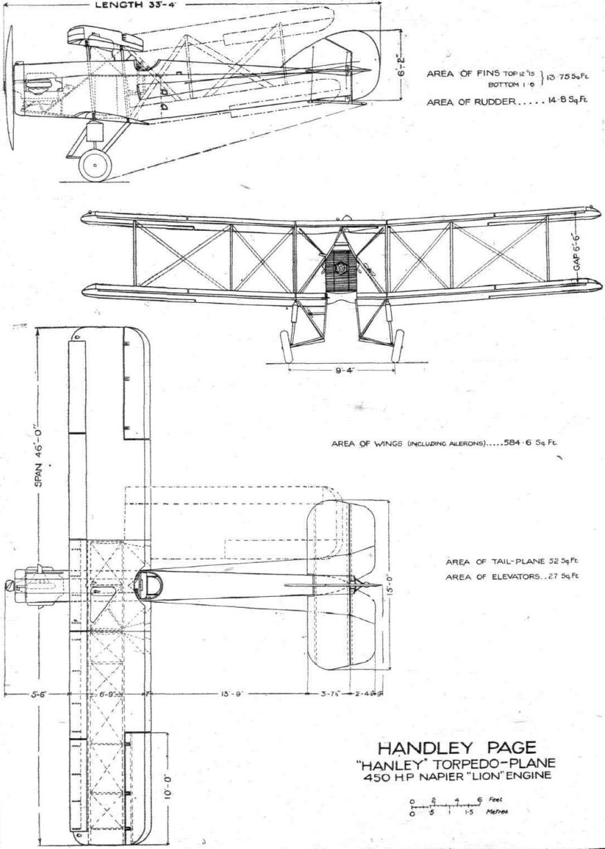
Having been designed for work from a ship, the "Hanley" had to incorporate certain features, such as low landing speed, small overall size, and folding wings. The first two desiderata form the reason for the use of slotted wings, while the last was a necessary evil (from the aircraft designer's point of view), which at first threatened to complicate to a very considerable extent the mechanism for opening and closing the slots. It will be shown presently, however, that these complications have been reduced to a minimum, and that – apart from the number of "gadgets" necessitated by the work for which the "Hanley" was designed, and which have nothing to do with the use of slotted wings - the control mechanism of a slotted wing need not be either complicated or heavy. The general lines of the "Hanley" are well illustrated in the accompanying scale drawings, which form a useful supplement to the photographs which we have already published. The undercarriage looks needlessly complicated, and as a matter of fact, a more recent model (the present notes refer to the first of the type) shows much cleaner lines, as will be seen from the accompanying photographs.
Owing to the restrictions already indicated, we propose in the following description to treat the "Hanley" solely as an interesting aeroplane, without too much reference to features which are connected with the special purpose for which the machine was designed. In other words, we shall deal with such aerodynamic and structural features as might be incorporated in any machine, no matter of which type. In this way our description may prove disappointing to a few who are interested in the machine chiefly as an instrument of war; but it should appeal no less on that account to those with whom the machine as an aeroplane is of first importance and the use to which it might be put a secondary consideration.
<...>
The Slot Control
At this point it may be of interest to discuss the manner in which the slots are opened and closed. To begin with, it should be stated that in the "Hanley," which is of course a biplane, the slots of upper and lower plane are operated independently, there being separate handles for the two sets of slots. The auxiliary aerofoils are, as already mentioned, hinged at points along their length, near their leading edge. The brackets which support these hinges are forward extensions of the wing ribs. The nose of the main aerofoil is covered on its upper surface with three-ply wood, as this surface forms one wall of the slot. Passing along inside the nose of the main aerofoil, underneath the three-ply covering, is a tube, which is carried in phosphor-bronze bearings on the nose ribs of the main aerofoil. This tube can be rotated from the cockpit (by means to be described presently), and carries at intervals lugs welded to the tube. These lugs have small projections, to which are hinged short L-shaped levers of U-section. The upper ends of these levers engage with eyebolts placed in line near the trailing edge of the auxiliary aerofoil. When, therefore, the tube is rotated in one direction, the levers rise, and in doing so open the slot. Rotation of the tube in the opposite direction closes the slot.
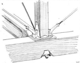
As regards the method of operating the slots from the pilot's cockpit, this is accomplished in a very simple manner. As the methods employed for upper and lower slots are the same, we will use as an example the control for the slots of the upper plane. One of our sketches shows the top centre-section, with the gravity petrol tank. In front of the front spar, is mounted a worm and worm-wheel gear. The worm is mounted on the forward end of the pilot's slot control tube, which runs in a fore-and-aft direction underneath the centre-section. On the end nearest the pilot is a short crank handle, turning of which turns the worm and, through that, the lateral tubes operating the levers of the slot control.
A short section of the transverse tube remains in position in the centre-section, and terminates at each end in a ball joint. The socket portion of this joint is formed in the ends of the wing tubes, and is slotted as shown in one of our sketches. The ball in the centre-section tube has a pin through it, the ends of which engage in the slot in the wing tubes, thus transmitting the torque. When the wings are folded the ball comes out of the socket, and on spreading the wings again all that is necessary is to ensure that the wing tubes are so placed as to allow of the slots engaging with the pins.
The slots in the lower plane are similarly operated, but the control for these runs from the starboard side of the pilot's cockpit down to the bottom centre-section, and upper and lower slots are separately controlled. The gearing between the worm and worm-wheel is such that it requires about 20 turns of the control handle to change from slot fully open to slot fully closed. Means are provided for preventing the pilot from "overwinding" the slot gear.
<...>
The Pilot's Cockpit
Owing to nature of the machine, a certain amount of restraint is necessary in describing the "office." The pilot's seat is placed just aft of the trailing edge of the top plane. In front of him he has an instrument-board with an unusually great number of "gadgets." Apart from the instruments necessary for flying, such as air speed indicator, altimeter, clock, compass, revolution indicator, radiator thermometer, etc., there are others whose functions are connected with the "freight" for which the machine is designed. The handles for operating the slots are placed, one in the top centre-section and one on the starboard side of the cockpit coaming. Then there is the handle for trimming the tail plane, and a wireless set with aerial, etc.
The controls, as already mentioned, are of usual type, with a wheel for the ailerons, fore and aft movement for the elevators, and a foot bar for the rudder. The cockpit is electrically lighted, with a number of small lamps illuminating the various instruments, and each capable of being switched on or off as required. The necessary current is generated by windmill-driven generators, placed outside the fuselage, in the slip stream from the propeller.
At the moment it is not thought advisable to publish figures relating to the weight and performance of the Handley Page "Hanley," except to state that the total loaded weight is about 6,400 lbs., which, with a wing area of 584, gives a wing loading of nearly 11 lbs./sq. ft. It is also of interest to note that the "cleaning-up" of the latest model has resulted in an astonishing gain in maximum speed. For this no doubt the simpler undercarriage is mainly responsible, although a good deal of the credit should probably be ascribed to the new Watts-Lang two-bladed propeller.
The ailerons of the first machine were found to give rather inadequate control at large angles of incidence. This meant that it was difficult to take full advantage of the low landing speed which the slotted wings made possible. In the new model the slotted ailerons have been found, during a number of recent test flights, to be extremely effective right up to the angle of maximum lift, with the result that it is possible to land the machine as slowly as the extra lift obtained with the slotted wings will allow. It thus appears that a necessary complement to the Handley Page slotted aerofoil is slotted ailerons. The manner in which these work has already been described in our recent article on the W.8C, in which they are to be used. It might be pointed out, however, that even on ordinary wings the slotted ailerons have been found very effective, and as the majority of machines could be landed considerably slower if the controls were effective at large angles, there would appear to be excellent reason for a wider adoption of ailerons of this type. Apart from the extra effectiveness, the slotted ailerons have the advantage that they are balanced, and consequently easy for the pilot to operate.
Описание:
- Flight, November 1922
THE HANDLEY PAGE "HANLEY" TORPEDO 'PLANE - Flight, January 1923
THE PARIS AERO SHOW 1922 - Flight, July 1923
Gothenburg International Aero Exhibition 1923 - Flight, July 1926
THE HANDLEY PAGE "HENDON"
Фотографии

-

Flight 1922-11 / Flight
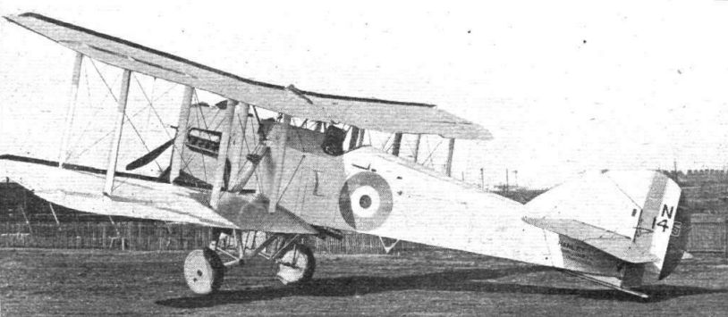
Регистрационный номер: N145 THE HANDLEY PAGE "HANLEY": Three-quarter rear view.
-

Flight 1922-11 / Flight
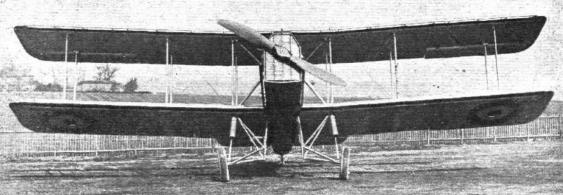
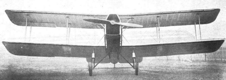
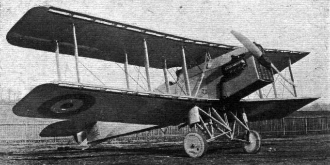
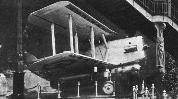
THE HANDLEY PAGE "HANLEY" TORPEDO 'PLANE: The front view gives a very good idea of the divided undercarriage which gives accommodation for the torpedo. The machine is fitted with slotted planes, and has slotted ailerons, which are found to be effective right up to the stalling angle.
-

Flight 1922-11 / Flight
THE HANDLEY PAGE "HANLEY" TORPEDO 'PLANE: Front view.
-

Flight 1922-11 / Flight
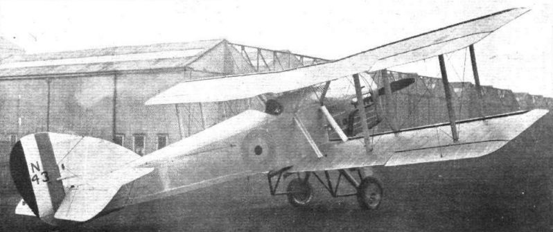
Another view of the Handley Page "Hanley'' torpedo 'plane, 450 h.p. Napier "Lion" engine: Three-quarter front view. The slots can be clearly seen in the picture. Although this machine is officially known as the "Hanley," it is affectionately called the "Heintz," owing to the number of levers which the pilot has to operate.
-

Flight 1923-07 / Flight
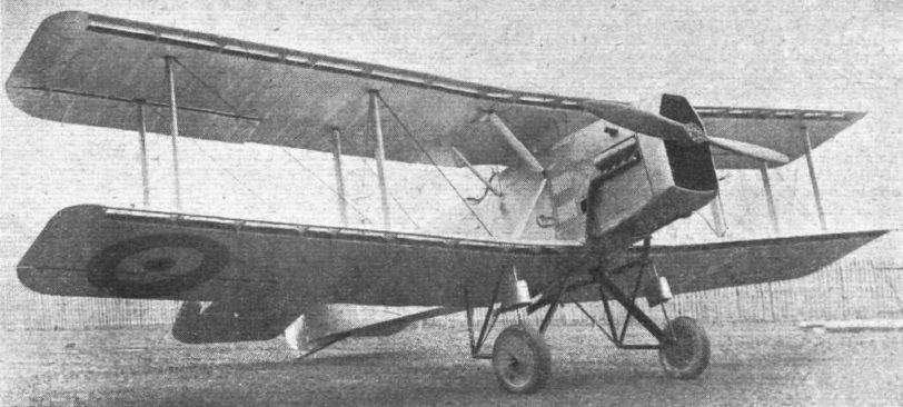
Регистрационный номер: N143 [4] The Handley Page "Hanley" No. 143 Torpedo Carrier: Three-quarter front view. These photographs show the latest type, which has been considerably "cleaned-up." Our description and scale drawings refer to the original model; but except for the undercarriage and slotted ailerons, our detail sketches refer to the new model as well. It is fitted with a 450 h.p. Napier "Lion."
-

-

Flight 1922-11 / Flight
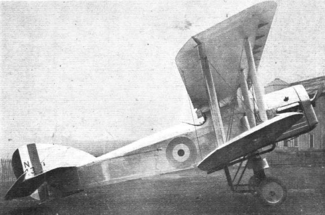
Регистрационный номер: N143 [4] THE HANDLEY PAGE "HANLEY": Three-quarter rear view.
-

Flight 1923-01 / Flight
The Handley Page "Hanley."
-
Flight 1923-08 / Flight
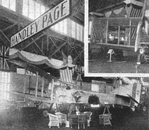
Регистрационный номер: N143 [4] BRITAIN AT I.L.U.G.: This set of photographs, kindly supplied by the S.B.A.C., shows some of the British exhibits at the Gothenburg International Aero Exhibition, which has just closed. The Handley Page "Hanley," with Napier "Lion."
-

Flight 1926-07 / Flight
Регистрационный номер: N9727 THE HANDLEY PAGE "HENDON": This is a torpedo plane with slotted wings. The engine is a Napier "Lion." The auxiliary aerofoils on the leading edge are of the more recent type, made from Duralumin sheet, which lie snugly against the leading edge when the slot is closed.
-

Flight 1926-07 / Flight
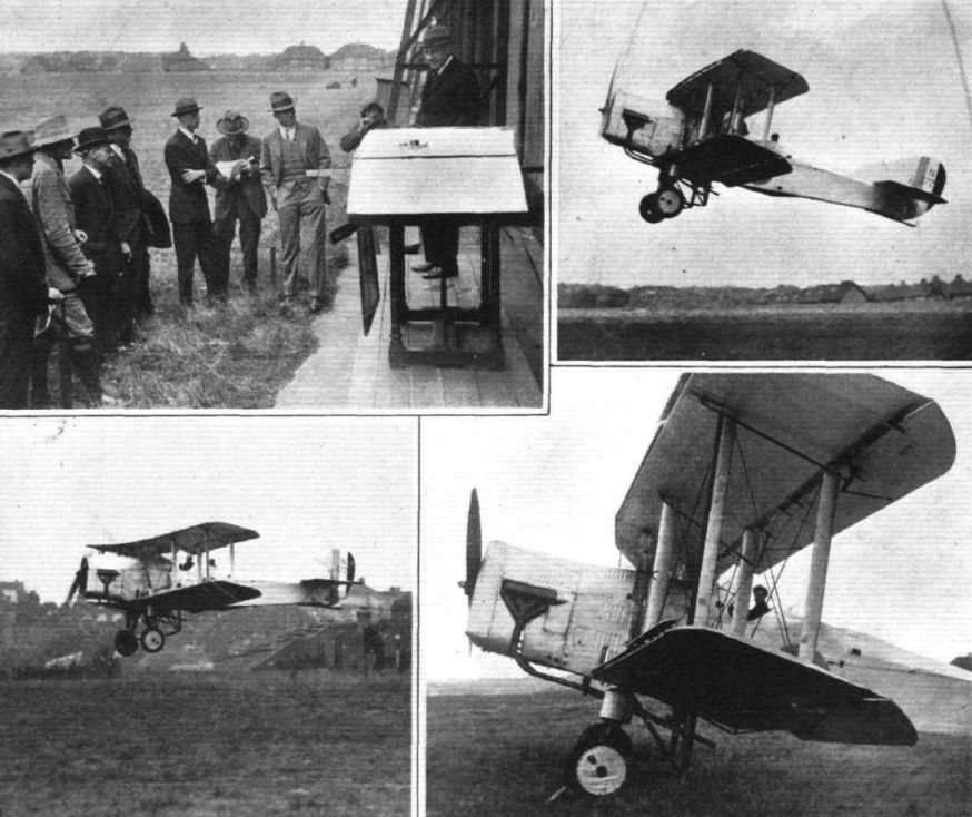
SLOT CONTROL: On Tuesday of last week a demonstration was given at Cricklewood of the new Handley Page "Hendon," which is fitted with leading edge slots and slotted ailerons. The photograph in the upper left-hand corner shows Mr. F. Handley Page explaining the action of the slots by means of a demonstration model. Major Davidson, U.S. Attache, nearest Mr. Handley Page, appears very interested. The upper right-hand photograph shows the "Hendon" taking off, piloted by Capt. Wilcockson. Note that the flaps are down and the slots open. On the left the machine is seen landing, and it will be noticed that, although the flight path is very steep, the machine is not tail-down. On the right a close-up view of the front of the machine. The lift-slot is only partially open, while the port control slot is fully-open and the port aileron down.
-

Flight 1926-07 / Flight
SLOT CONTROL: Diagrammatic representation of the system used on the Handley Page "Hendon." There is a main slot and a main trailing edge flap, which are used to give extra lift, while the wing-tip slots and flaps are used chiefly for control. On the left is shown the position occupied by the flaps and slots for slow flying. The control slots and their flaps are still available for lateral control. The position shown in the centre corresponds to fast flying with lift slot closed and main flap neutral, while the starboard control slot is open and its flap down, to produce anti-clockwise roll. On the right, the position in normal straight flight with slots closed.


-

Flight 1922-11 / Flight
Standard fuselage fitting of the Handley Page "Hanley."
-

Flight 1922-11 / Flight
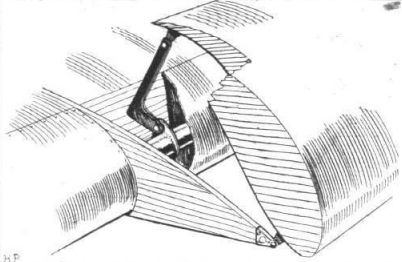
Slot-operating mechanism of the Handley Page "Hanley."
-

Flight 1922-11 / Flight
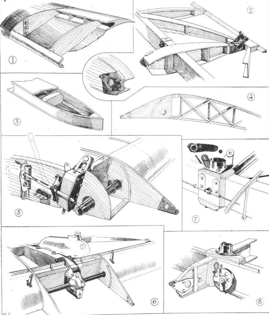
THE HANDLEY PAGE "HANLEY": Some constructional details of the wings. 1, partly-sectioned view of a portion of the auxiliary aerofoil. In shape this resembles the famous Joukowsky wing section. 2, shows the construction of an aileron. Note the triangulated construction. The shackle near the trailing edge receives the wire to the top aileron, while the fitting on the nose fo the rib shown in more detail in the inset sketch, is for the return cable. 3, section of the end portion of a built-up box spar. Note the triangular section corner strip, which provides large glued area. In 4 is shown one of the double lattice ribs which carry the brackets on which the auxiliary aerofoil is mounted. The nose of the main aerofoil is formed by thin three-ply, bent over the small curved strip screwed to the bracket. 5, details of the locking pin and spar fitting on the lower plane at the point where the wing is joined for folding. A lever is used for pulling back the locking bolt when the vertical slide at the back has been raised. 6, details of the slot operating mechanism. The tube from the pilot's controls carries on its front end a worm, which engages with a worm wheel on the transverse tube in the leading edge. Rotation of this tube raises or lowers the auxiliary aerofoil through levers hinged to lugs on the tube, thus opening or closing the slot. 7, inter-plane strut socket on the lower plane rear spar. 8, lower spar, with bracket for aileron hinge.
-

Flight 1922-11 / Flight
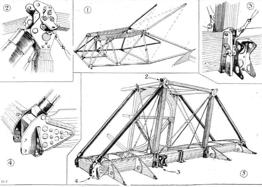
THE HANDLEY PAGE "HANLEY": Some constructional details. 1, View of the engine mounting. 2, Attachment of sloping strut to vertical strut and longeron. 3, Brackets for attachment of engine tubes and slot control gear. 4, Lower attachment of sloping strut to wing root spar. The lug projecting forward carries the slot control tube. 5, General view of front portion of fuselage with lower wing spar roots, sloping tubes, etc.
-

Flight 1922-12 / Flight
Handley-Page "Hanley"
-

Flight 1922-11 / Flight
Handley Page "Hanley" Torpedo-Plane 450 hp Napier "Lion" Engine

- Фотографии