

Flight, November 1923
THE AEROMARINE METAL-HULL FLYING BOAT
RECONSTRUCTED war-time aircraft have been used by the Aeromarine Airways in the U.S.A. since the beginning of their operations in 1920 with more or less success, yet these operations clearly indicated that for future use a more efficient, particularly from the point of maintenance and reserve power, flying boat would be needed.
The problem of development of a boat of this type was placed in the hands of the engineers of the Aeromarine 'Plane and Motor Company, Keyport, N.J., early in 1922. Preliminary work on the design and construction was immediately started. The boat to be replaced was the old converted H.S.-2L - six passenger, beach-hopping machine.
Beach-hopping requires a flying boat with a strong bottom, quick take off, good climb, and with sufficient fuel capacity for either short or long distance flights. The hull must be seaworthy as much of the flying is over open ocean, and the whole machine must be so constructed as to require as little maintenance as possible while anchored in a protected harbour.
The Liberty motor, which is available in quantities in the United States, was decided upon for the power plant, and in accordance with these requirements a design was laid down for a biplane flying boat with a metal hull and tail surfaces and spruce and fabric wings. The upper wing was made with a larger span and chord than the lower in order to improve the aerodynamical efficiency of the structure and avoid damage in high seas. The ailerons were fitted to the upper wings only and were designed to be very large for control at low speed.
The comfort of the passengers in the hull was the first consideration. Seaworthiness, ease of take-off, and low air resistance were also given consideration. The hull, as laid down, is wide enough to accommodate four passengers abreast in the rear seat and three in the forward seat, a crew of two, with dual control, being located back of the passengers and directly forward of the lower front wing beam. The bottom has a V with an inclined angle of 152° at the step and the angle is still sharper at the bow. The step is 5 ins. deep and the bottom back of it raises up to an angle of 8° towards the stern and is V-shaped, ensuring clean running before take-off, and seaworthiness.
The wing tip pontoons are of very good streamline section, square in cross section, turned up on edge so as to break the force of the water in case of contact in high seas.
Details of Construction. - The wings are constructed of built-up trussed ribs and spruce I-beams, braced with internal bracings of hard wire; the upper wing is of three panels. The centre section panel, which supports the petrol tanks is rigidly mounted on the motor support. The outer panels are cut away for the ailerons, which are narrow and fitted to the upper wing only and extend two-thirds the total wing spread. The small balancing panels, mounted on duralumin masts, with general narrowness and straight ends, constitute a very light and effective lateral control. The aileron control cables are run in tubes inside the wing panels, which reduces air resistance and makes the controls readily removable. All air controls are mounted on ball bearings.
Seventeen S alloy is used for the framework of the tail surfaces. Channelled sections of 22 B. and S. gauge metal are employed for the wings and minor braces; 20 gauge material for the built-up boxed sections, and 18 gauge is used for the fin post, while 1/16th in. wall tubes are used for the rear beam of the stabiliser and for the elevator and rudder beams. All joints are riveted. The weight of this structure while much stronger than the usual wooden construction is but 53 lbs per sq. ft. of area.
As low maintenance was the first consideration, the power plant installation received very careful attention. The motor support is built up of heavy steel tubing with the exception of the motor-beds, which are of laminated spruce and ash. This support is attached to the hull, which affords a wide base. The whole structure requires no cable bracing whatsoever.
A cartridge tube radiator, swung from the upper panel and steadied from the engine bed, has a frontal area of 620 sq. ins. A full face shutter control, operated from the pilot's cockpit, regulates the air flow.
Two 50-gal. 3s. alloy welded petrol tanks mounted in the centre panel and one 70-gal. reserve tank in the hull constitute the petrol system, the 70-gal. tank being used for long flights only and is separated from the main system by a shut-off valve. A visible petrol gauge, located in the hull, shows the amount of fuel in the lower tank; separate gauges in the upper tanks indicate their condition. All three tanks weigh but 60 lbs. for a petrol capacity of 170 gals. One-inch 3s. alloy piping connects the tanks. The petrol is fed by gravity from the main tanks to the carburettor, which eliminates the head resistance of a fuel pump and assures reliability under all operating conditions.
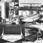
The hull, which is the first all-metal hull to be constructed in America, is the most interesting feature of this flying boat. The framework consists of 18 frames and five water-tight bulkheads and fore and aft stiffeners on deck and bottom; all frames and stiffeners are made of the same size U-shaped sections; fittings of metal varying from 0-040 to 1/16th in., depending upon the place where used; U-shaped sections pressed out of flat sheet, with flanges to which the covering is riveted on assembly. Thus, when the work is completed, no edges are left exposed, and the rounded back of the section is pleasing to the eye and practically immune from abrasion. Adherence to the same size of section greatly simplified the making of all joints between members, and incidentally saved lots of space in stock room. The bottom members of the frames (floors) are of box section, built up of two solid 17s. alloy webs and channel top, all riveted together. In one of our illustrations we show a typical frame in front of the step, at rear passengers' seat. In this case an additional cross member was required to support the seat, and from this member to the bottom the frame is covered with 17s. alloy sheet, forming a big storage space in the hull back of it.
The covering is of 3/64th in. thickness on sides and top of hull, and of 1/16th in. thickness on bottom ahead of step. The covering is riveted to the frames and stiffeners with 17s. alloy rivets. The chine, sponson clamp and deck clamp are made of 1/16th in. metal throughout, and are riveted over the covering. The bottom of the boat is quite smooth and clean, all stiffeners or keelsons being placed inside where they are protected from damage in handling of boat. This feature certainly will be appreciated by those who want the boat to give long and faithful service without annoying and costly repairs.
To protect the bottom further the heavy oak keel is provided. This keel is not a part of the structure, and can be quickly taken off and replaced when worn out. Strong metal keelson inside of boat is dependent solely to give required strength. Anxious as the designers were to get a lighter and better performing boat, they always remembered that service is paramount, and did not try to skim over any of the requirements derived from the practical commercial operation of Aeromarine flying boats.
Performance. - Over 200 flights have been made in this ship with only two forced landings - one due to the clogging of carburettor jets, and the other to a faulty ignition switch; in both cases the trouble was remedied without outside assistance, and the trip continued without delay.
Since this boat was launched on June 1 it has never been in a hangar. There was much criticism by the old boat builders on the thin metal used in the construction, the exposed rivet heads on the bottom, and the use of "aluminium" in salt water. The thin metal has justified itself in that there has been absolutely no leakage in the hull; the rivet heads in the bottom have not caused any inconvenience in getting off; in fact, this boat gets off in less time by several seconds than the old type boat under its best flying conditions, and the 17s. alloy has not corroded in salt water, although at times the whole surface of the bottom has been exposed to the action of the water. Immediately after launching the boat was put into operation, and on the third day a trip was made from Keyport to New York with company officials. Performance trials followed without the slightest mishap. Every day confidence in the boat was increasing. Up to the present time the boat has actually made more than 200 flights; been in the water more than three months; and flown a total of over 70 hours. The log of the boat shows that more than 800 passengers have been carried, exclusive of crew, and a distance of 4,800 miles has been covered; all of this without the least bit of loss in performance due to water soakage or deterioration.
The specifications of the A.M.C. are as follows :-
General. - Type, flying boat, biplane; purpose, commercial, passenger carrier; number in crew, two (2); passenger capacity, for flights of 7 hours' duration, 5; for flights of 4 hours' duration or under, 7.
Dimensions. - Span, upper wing, 65 ft.; span, lower wing. 48 ft. 6 1/2 ins.; length, overall, 32 ft. 10 ins.; chord, upper wing. 7 ft.; chord, lower wing, 5 ft. 1 in.; angle of incidence, both wings, 4 1/2°; dihedral, lower wing, 3°; wing curve, upper, Aeromarine No. 2; wing curve, lower, Aeromarine No. 6.
Areas. - Upper wing with ailerons, 434 sq. ft.; lower wing. 218 sq. ft.; total wing area, 652 sq. ft.; horizontal stabiliser, 53.sq. ft.; elevator, 35.5 sq. ft.; vertical fin, 21.5 sq. ft.; rudder, 21.6 sq. ft.
Weights. - Weight, fully loaded, 6,100 lbs.; weight, empty, with water, 3,660 lbs.; disposable load: five passengers 900 lbs.; crew of two, 360 lbs.; anchor and rope, 60 lbs.; miscellaneous equipment, 60 lbs.; fuel and oil, 1,060 lbs.; total disposable load, 2,440 lbs.; load per sq. ft., 9-35 lbs.; load per h.p., 15-25 lbs.
Performance. - High speed (1,700 r.p.m.), 98 m.p.h.; cruising speed (1,400 r.p.m.), 80 m.p.h.; min. flying speed (1,150 r.p.m.), 60 m.p.h.; landing speed (estimated), 50 m.p.h.; ceiling, absolute, 14,000 ft.; climb in 10 minutes, 3,300 ft.
- Flight, November 1923
THE AEROMARINE METAL-HULL FLYING BOAT
Фотографии
-
Flight 1923-11 / Flight
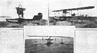
THE AEROMARINE METAL-HULL FLYING BOAT: Three views of the complete machine: Top, left, side view; right, three-quarter front view; and, below, front view of the machine in the water. It is fitted with a 400 h.p. Liberty engine.
-
Flight 1928-09 / Flight
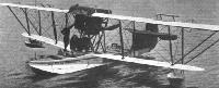
CANADIAN COMMERCIAL AIRCRAFT: A Curtiss flying-boat which was employed by the Fairchild Air Transport on the Haileybury and Rouyn service.
-
Flight 1923-11 / Flight
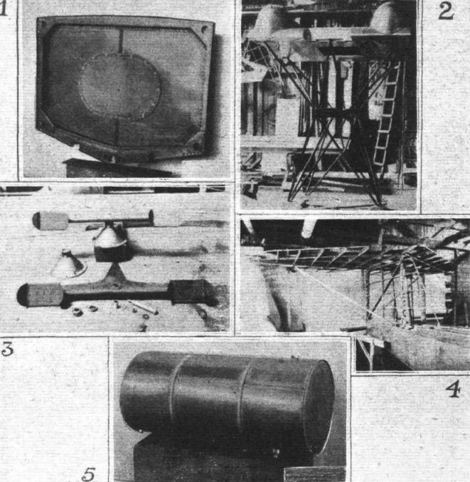
Some Details of the Aeromarine Metal-Hull Flying Boat: 1. Front view of the complete machine. 2. Radiator installation, attachment of motor support, and centre section strut. 3. The complete duralumin hull. 4. One of the transverse frames in hull, ahead of step. 5. The bow of hull.
-

Flight 1923-11 / Flight
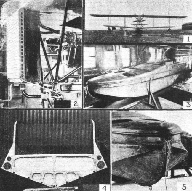
Constructional Details of the Aeromarine Metal-Hull Flying Boat: 1. Bulkhead No.17. 2. All-steel tubing engine mount with engine section panel, and two 50-gal. petrol tanks. Note absence of bracing wires. 3. Rudder bar and details. 4. Tail unit, uncovered. 5. Three - S. alloy welded petrol tank, 50 gals., 185 lbs.

- Фотографии