M.Simons The World's Vintage Sailplanes 1908-45
THE SCUDS
<...>
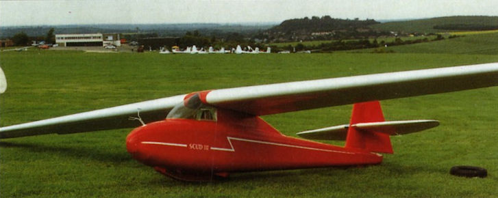
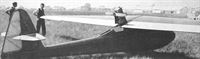
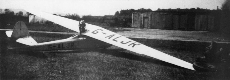
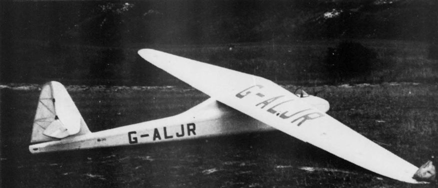
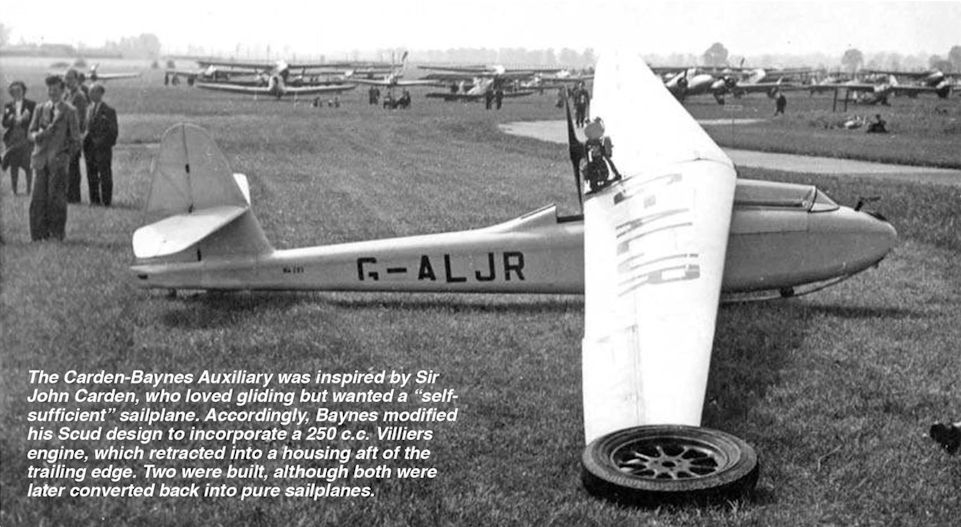
In 1935 Sir John Carden commissioned Baynes to design a self-launching sailplane called the Carden Baynes Auxiliary. Although owing much to the Scud 2, this was a quite different design with a streamlined fuselage and cantilever wings mounted on a tall pylon. The wing was of larger span with a new aerofoil of Baynes’ own design. The fully retractable motor was a 249 cc 9 hp, Villiers motor-cycle engine. The Auxiliary was at the time the lowest-powered aeroplane ever to have flown successfully. Unfortunately, before he could take delivery, Carden was killed in an airline accident near Croydon. A second Auxiliary was constructed at Farnham but both were eventually sold without their engines. They were then known as Scud 3 sailplanes. The Villiers motor went to the Science Museum in Kensington.
After the Second World War both Scud 3s and one of the Scud 2s survived. The Scud 2 was the one built by Slingsby from the Collins components. It was rebuilt by Vic Ginn and in 1950 began a second life. John Jeffries of the London Gliding Club logged over 200 hours in it, and made several flights of 100 km distance. This is almost without doubt the oldest airworthy sailplane in the world although after the rebuild before 1950, it may be that not all the original structure remains. At least one Scud 3 was also still flying in 1980.
Technical data:
Scud 3: Span, 13.87 m. Wing area, 11.15 sq m. Aspect ratio, 16. Flying weight, sailplane version, 204.12 kg. Wing loading 18.31 kg/sq m. Aerofoil, Baynes.
Показать полностьюShow all
Flight, May 1935
FLYING ON 250 c.c.
Villiers Two-stroke Motor Cycle Unit as "Occasional Engine" for a Sailplane: The Outcome of a Startling but Practical Scheme Conceived by Sir John Carden
SEVERAL attempts have been made from time to time to combine the glider or sailplane and the power-driven type of aircraft in one machine. Many of the ultra-light 'planes which took part in the Lympne competitions some years ago were virtually gliders with small motor cycle engines fitted. Although these machines were remarkably efficient, regarded as aeroplanes, they did not achieve L /D ratios comparable with those which the modern type of sailplane attains. The very fact that the engine and airscrew were exposed to the airstream increased the drag very materially and reduced the efficiency from the sailplane point of view.
With a pure and simple glider, on the other hand, a very high L/D ratio is achieved by having a very large wing span, so as to obtain low span loading with consequently low induced drag. To get into the air such a machine must, however, be launched either by a ground crew catapulting it off by means of rubber cords, or by towing behind a motor car or an aeroplane. It is often possible, if a height of some hundreds of feet can be attained initially, for such a machine to reach a region where strong up-currents exist, and by making use of these the pilot can often make cross-country flights of considerable duration.
If the sailplane gets out of one up-current, however, it may not be able to reach another before it has lost too much height, and will then have to land. In most cases this means that the pilot has to telephone back to his starting point, and a car with a trailer has to be sent out to find him and bring him back. All this is something of a handicap to the sailplane pilot, and if means can be found to enable him to regain his base without outside assistance his independence would be vastly increased, and, moreover, he would probably be able to put in many more flights in the course of a day.
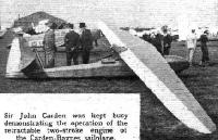
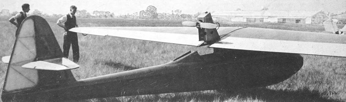
Sir John V. Carden, who has been a keen amateur pilot for a good many years, and who has owned several aeroplanes (his present mount is a Miles "Hawk"), has had the brilliant idea of utilising an "occasional" power plant; in other words, his engine is ordinarily mounted in a position out of the airstream; but when it is wanted, either to get the sailplane off the ground initially, or for reaching a region of up-currents, it can be put into operating position and started, the machine then proceeding as an ordinary low-power aeroplane.
It might have been thought that to do this would have been a very difficult task. Sir John has, however, schemed out an amazingly neat and simple method. In his work he has had the whole-hearted co-operation of Mr. L. E. Baynes, the designer of the very successful "Scud" sailplanes, and of the Villiers Engineering Co., Ltd. Mr. Baynes has designed for this extremely interesting development a new high-efficiency sailplane which has been constructed at the Abbott Motor Works, Wrecclesham, Surrey, where Flight last week had an opportunity of inspecting the new craft.
Engine Reliability
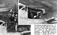
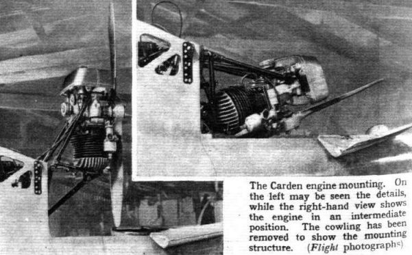
The engine which Sir John Carden is using is a single-cylinder Villiers two-stroke of 249 c.c. capacity. In its normal form this engine is, of course, an ordinary motor cycle engine with its cylinder pointing upwards. For the sailplane it was desired to invert the engine, since by doing this the centre of the crankshaft would be raised, thus giving the necessary airscrew clearance with very small overall height. The Villiers Company very sportingly undertook the work of converting the engine, and the tests which Sir John has had carried out at Wrecclesham have been extremely satisfactory; the engine has run for many hours on end at full throttle without any trouble and without any signs of overheating, the cowling being so arranged that it forms a venturi, while the airscrew blades passing close behind the cylinder help to produce a very strong air current.
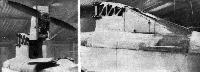
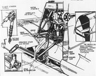
The mounting of the engine is very simple. Two tubes having a diagonal bracing member run to the crank case and vee tubes to the cylinder head, so that the whole system is perfectly triangulated and a very rigid mounting provided. The engine is raised into operating position or retracted into the fuselage very simply by a tube joined to the nut of a large threaded shaft or worm. This worm is rotated by a handle in the cockpit driving a chain and sprockets. Rotation is one direction makes the nut advance along the worm and lowers the engine, while rotation in the opposite direction causes the nut to travel backwards and raises the unit into the operating position.
A very ingenious "lid" has been produced for the fairing. When the engine is in the operating position this lid is held open by a spring, but as the engine is lowered the airscrew presses on a lever which overcomes the tension of the spring and, by a system of cranks and levers, causes the lid to close. When the engine is retracted the surface is very smooth and offers no extra drag.
It is necessary to stop the airscrew in a vertical position, since otherwise it will not go into the narrow space provided for it in the fuselage. This is done by a stop worked in conjunction with the lever of the starting gear. The latter consists of a ratchet wheel between two pulleys. When the starting lever in the cockpit is pulled back the cables pass over the pulleys until the chain engages with the ratchet wheel, which is, of course, on the forward end of the crankshaft. Continuing the pull causes the ratchet wheel and the crankshaft to rotate, and the engine starts. The stop provided for ensuring that the airscrew is vertical is operated by a lever on the starting handle, so arranged that the latter can only be pulled back to a predetermined position, in which the airscrew is vertical.
The cowling in front of the engine and the petrol tank above the engine are finished in a gold paint which harmonises extremely well with the varnished wood finish of the machine, and is a great improvement on the plain aluminium finish usually found.
Constructional Materials
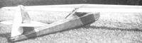
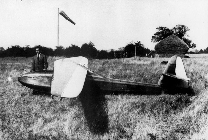
The Carden-Baynes sailplane itself is a very interesting machine of the modern high-efficiency type, with very large span and heavily tapered wings. It is, of course, of all-wood construction, the wing having a plywood-covered nose and fabric-covered trailing portion, while the fuselage is planked with plywood and spruce.
A portion of the wing section which Mr. Baynes has used is of the highly cambered type, but at the root, where the wing joins the fuselage, the lower surface is flat. Two objects are achieved by this arrangement: first, the spars can be made a good deal deeper at the root, where extra strength is required (the wings being pure cantilever), and, also, a better shape of joint is secured, thereby probably reducing interference drag between root and fuselage. Towards the tip the wing section begins to change, and at the tips it becomes one of small chord and thickness and of reflex curvature.
The aerodynamic reasons for this progressive change of section and, incidentally, also angle of incidence, is to ensure that the centre portion of the wing shall stall first. A gentle dropping of the nose is further ensured by the fact that the trailing edge is nearly straight and the leading edge swept back to it so that a certain measure of the stability of the tailless aeroplane is achieved. The ailerons, by the way, are differentially operated, so as to avoid adverse yawing moments.
For transport the wings can be quickly removed from the fuselage and stacked alongside it on a trailer. The two halves of the tailplane are also easily removable, and the whole machine can be dismantled in a few minutes.
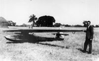
The undercarriage has been reduced to the simplest possible form and consists of a single wheel mounted partly inside the floor of the fuselage. When the machine is at rest it tilts over with one wing tip on the ground, but the weight on the wing tip is very small, and as soon as the machine begins to gather speed the wing can be lifted by using the ailerons.
Cruising at 35 m.p.h.
A very good aerodynamic form has been chosen for the fuselage and considerable trouble has been taken to keep air drag as low as possible. For a height of some 10 to 12 inches the fuselage sides are flat, but the top and bottom are curved. Over the rear portion the covering is of plywood, but in the nose, where double curvatures occur, it would not be possible to use sheet material, and a built-up structure has been employed, consisting of two layers of narrow spruce strips laid on diagonally, the strips of the two thicknesses crossing each other at approximately right-angles. The whole of the woodwork is left in its varnished state without paint, a finish which looks very attractive and is somehow reminiscent of small boat building. The workmanship and finish are of a very high order, and the price will not be remarkably low. Until the Carden-Villiers auxiliary unit is ready (the present being merely an experimental unit produced to try out the principle) it is difficult to estimate production costs, but Flight understands that it is hoped to market the machine at ?250.
The direct-drive airscrew looks almost ridiculously small, but the fact that the engine is of low power (it develops 9 h.p. at 3,500 r.p.m.) has made it possible to use a small diameter, and consequently the ratio V/nD at low forward speeds is such that quite reasonable airscrew efficiency can be obtained; the static thrust and thrust at low forward speeds are quite high, the pitch angle being so small that even at very low forward speeds the blades are not stalled.
The machine has been designed for a cruising speed of approximately 35 m.p.h., and this will also be the speed at which the best rate of climb is attained. The very tiny petrol tank of the engine unit contains sufficient fuel for a flight of a little more than half an hour's duration, and it is thought that this will be sufficient for reaching with a margin to spare, a height where soaring is possible. Having reached this height the pilot will stop his engine, pull the starting handle slowly until the airscrew is vertical, and then wind-in his engine. He then has a pure sailplane with an L/D ratio of about 24. Should he get out of the up-current he will raise his engine into the operating position, start it, and proceed until he has found another up-current.
Показать полностьюShow all