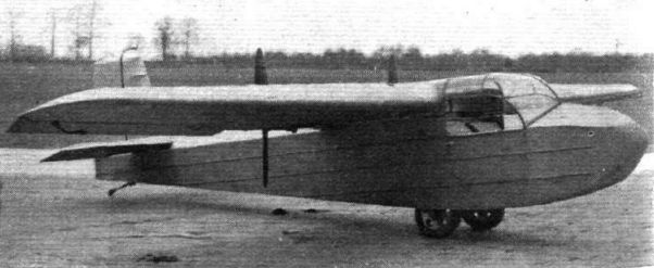
Flight, March 1937
A BABY TWIN
Two "Buried” Engines and Pusher Airscrews Among the Striking Features of the Two-seater Carden-Baynes Bee
LAST March, Carden-Baynes Aircraft, Ltd., was formed to build a two-seater, high-wing, twin-engined monoplane, known as the Bee, to the designs of Mr. L. E. Baynes. Two special 40 h.p. Carden S.P.i engines, evolved by the Carden-Baynes Company from the standard 30 h.p. Carden, were specified, being arranged to function lying on their sides and driving their pusher airscrews through integral extension shafts.
A one-man folding-wing system, the principle of which is well brought out in the accompanying sketches, is incorporated, and there is a door on each side of the cabin.
The construction is mainly of wood, and is not lacking in novelty.
It is estimated that the Bee will cruise at 100 m.p.h.
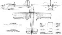
The main data are: Span 29 ft. 10 in., length 23 ft., height 4 ft. 9 in., weight empty, 880 lb., weight loaded, 1,350 lb.
AN INTRIGUING TWO-SEATER
Untrammelled Design by Mr. L. E. Baynes: Flat "Buried" Engines and Pusher Airscrews Feature in the Bee Monoplane
TWIN-ENGINED security, pusher airscrews, ample performance and vision and non-acrobatic entry and exit are desiderata generally acknowledged by regular users of private aircraft. Singly, each of these qualities has at one time or another characterised some British light aeroplane, but the incorporation of them all, without the sacrifice of one or more of their number, is a task demanding much originality of thought and ingenuity of design.
Mr. L. E. Baynes seems to have made a very stout effort toward the efficient embodiment of all these properties ill a side-by-side two-seater monoplane which has been christened the Baynes Bee. Until Capt. Hubert Broad has got well into his tests of the prototype it would be premature to discuss the machine's flying characteristics, but he is said to be quite enthusiastic.
In general the Bee is a side-by-side two-seater high-wing monoplane with two 40 h.p. Carden-Baynes pusher engines mounted within the wing.
Spruce and three-ply are mainly used for the wing and fuselage, both of which components embody a number of unorthodox features.
The cantilever wing, tail plane and fin are each built round what are virtually two parallel spars with laminated webs on one side only, being joined by diaphragms or bulkheads and covered on top and bottom with ply sheeting. Thus the whole forms a substantial box beam with square booms at each corner. For this method of construction Mr. Baynes claims exceptional cheapness as compared with more conventional two-spar wings with ply covering to take the torsional bracing. He gives two main reasons: the booms of the spars do not require a bevelled outer surface changing along the span, and, as the front and rear sides of the beam are parallel, the square ply sheets on top and bottom are easier to apply than is the curved and tapered ply covering of more normal wing designs. The similarity of the spars also makes for ease of production.
The desired profile is provided by ribs slipped over the main beam and covered with fabric. The air space between the fabric and the ply is claimed to benefit the durability of the ply under severe climatic conditions and to facilitate maintenance.
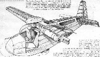
Attachment of the wing to the fuselage is made at three points, the withdrawal of pins at the two front joints allowing the wing to swivel round the third joint into a fore-and-aft position over the fuselage. For steadying purposes two light-alloy turntable rings are fitted, one to the under surface of the wing and the other to the top of the fuselage.
A straightforward plywood box with flat sides, the top being faired with a fabric-covered hinged coaming, the fuselage extends to the rear edge of the rudder to facilitate ground handling. Forward of the wing is the cabin, which has a large door on each side and is amply provided with Rhodoid panels. Entry and exit are as easy as, and outlook much better than, from a typical saloon car. Over the C.G., behind the side-by-side seats, is a luggage compartment measuring 3ft. 8in. by 2ft. 3in. by 1ft. 3in., giving a capacity of over ten cubic feet. Access is obtained by pulling forward the hinged backs of the seats, which, incidentally, are provided with recesses for parachutes. The usual complement of Smith's instruments is specified. Engine instruments are grouped on two small panels on each side of the cabin.
The control column is T-shaped, permitting dual control. One arm is detachable. A commendable feature is a central box structure between the seats containing the aileron control shaft, wires, dual throttle controls and the wheel operating the elevator trimming tabs.
The design of the undercarriage is another feature of unusual interest. Two cantilever oleo legs are attached internally to the fuselage sides, half the Dunlop wheels (which have a marked "toeing-out") projecting through the bottom of the fuselage. In the vicinity of the undercarriage the bottom of the fuselage is covered with a detachable metal panel permitting inspection and detachment of the wheels. This cowling projects on each side of the fuselage, forming small vanes which act as mudguards and prevent splashing of the airscrews. At first glance the track might appear barely wide enough, but on consideration of the relatively low wing and C.G. position it is claimed to be ample. Wheel brakes are specified and the tracking leaf-spring tail skid has a small roller shoe.
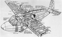
The two Carden-Baynes S.P.1 water-cooled four-cylinder engines are of a new type, giving, with the assistance of Centric blowers running at 1.1 times engine speed, 40 h.p. at 3,500 r.p.m. The mountings are steel girder structures with sandwich plates between the cylinder block and sump casting, there being appropriate lugs for attachment to the spar, from which the whole unit is cantilevered. The engines and radiators (which lie alongside) are entirely submerged in the wing, cowling panels being hinged to the rear of the wing spar. The extension shafts for the airscrews are integral with the engines.
The air inlets for cooling are below the wing with the outlets above. Air is induced by the difference in pressure on the top and bottom surfaces of the wing and the suction of the airscrews. This arrangement, it is claimed, tends to give constant cooling.
Ten gallons of fuel are carried in leading edge tanks.
- Flight, March 1937
A BABY TWIN
Фотографии
-
Flight 1937-11 / Flight
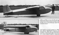
An interesting development of which more may be seen when suitable power units are available - the twin-engined Baynes Bee.
-
Aeroplane Monthly 1992-07 / W.Morse - Baynes: the unknown innovator
Two views of the Bee showing the excellent field of vision for the pilot. The narrow-track undercarriage must have made the Bee prone to groundlooping, despite the steerable tailskid.
-
Aeroplane Monthly 1992-07 / W.Morse - Baynes: the unknown innovator
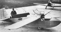
The newly-completed Baynes Bee at Heston on March 23, 1937, with a more conventional two-seater - a Miles Hawk Major behind. A few days later, on April 3, Hubert Broad took the Bee off from Heston on its maiden flight. Although it was registered G-AEWC, it is almost certain that the Bee never wore these marks.
Другие самолёты на фотографии: Miles Hawk / M.2 - Великобритания - 1932
-
Aviation Historian 27 / T.Buttler - The Oldest Swinger
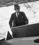
It seems that Leslie Everett Baynes AFRAeS was somewhat camera-shy, there being few photographs of this highly inventive and creative designer readily available. This detail from a larger photograph shows Baynes beside the sole Carden-Baynes Bee in 1937. Born in Barnes, West London, in March 1902, Baynes joined Airco at Hendon at the age of 16 before moving on to Short Bros at Rochester in the 1920s.
-
Aeroplane Monthly 1981-09 / A.Ord-Hume - Carden Baynes twin Bee
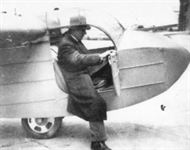
L. E. Baynes demonstrates the ease of access into the Bee. The canopy, when opened, simply lay back along the top of the centre section.
-
Aeroplane Monthly 1981-09 / A.Ord-Hume - Carden Baynes twin Bee
In 1934 Baynes formed Carden-Baynes Aircraft Ltd with Sir John Carden, although the latter was sadly killed in an air accident on December 10, 1935. The company continued, however, and in April 1937 the two-seat twin-pusher-engined Bee made its first flight.
-
Aeroplane Monthly 1981-09 / A.Ord-Hume - Carden Baynes twin Bee
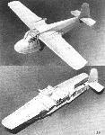
Another neat Baynes innovation was the Bee's swivelling wing, which could be rotated 90 deg. to enable it to rest on top of and in line with the fuselage.
-
Flight 1937-03 / Flight
These two sketches illustrate the ingenious "turntable" wing-folding system of the Carden-Baynes Bee.
-
Flight 1937-03 / Flight
The Carden-Baynes Bee is of interest not only because of its unusual layout but because it incorporates a number of unusual structural features, particularly, as visible in this sketch, in the wing. Petrol is carried in leading edge tanks. The accessibility of the cabin is particularly commendable: the doors are large and the fuselage low.
-
Aeroplane Monthly 1992-07 / W.Morse - Baynes: the unknown innovator
The main features of the Carden-Baynes S.P.1 engines and of their installation in the wing of the Bee are revealed in this sketch. The mountings are steel girder structures with sandwich plates between the cylinder block and sump casting. The engine and radiators (which lay alongside) were entirely submerged in the wing - the extension shafts for the propellers were integral with the engines. By mounting the engines on their sides, the wing was free of any protuberances.
-
Aeroplane Monthly 1992-07 / W.Morse - Baynes: the unknown innovator
Baynes Bee. Two 40 h.p. Carden-Baynes S.p.1 engines.
-
Aeroplane Monthly 1981-09 / A.Ord-Hume - Carden Baynes twin Bee
BAYNES BEE Two 40 h.p. Carden-Baynes S.P.I engines
- Фотографии


