Cierva C.4 / C.5
Страна: Испания
Год: 1923
Автожир

Описание:
Cierva (автожиры X. Сиервы)
Flight, May 1923
THE CIERVA "AUTOGIRO"
Flight, August 1923
MORE ABOUT LA CIERVA "AUTOGIRO
Фотографии

Cierva (автожиры X. Сиервы)

<...>
   Экспериментируя с моделями, Сиерва опытным путем пришел к применению несущего винта с шарнирно закрепленными гибкими лопастями несущего винта для преодоления дисбаланса в подъемной силе между идущими по потоку и навстречу ему лопастями. В 1922 году на основе этой теории построили вариант С.4 с четырехлопастным несущим винтом, лопасти которого крепились к втулке на шарнирах. Эта машина впервые успешно взлетела 9 января 1923 года. Хотя в этом полете аппарат пролетел всего 183 м, он подтвердил правильность выбранной концепции. В конце того же месяца автожир С.4 за 4 минуты пролетел 4 км по замкнутому маршруту на высоте около 30 м. С.4 оснащался ротативным мотором Rhone 9Ja мощностью 110 л. с. (82 кВт). В июле 1923 года взлетел автожир С.5 с аналогичным мотором и трехлопастным несущим винтом. После этого Сиерва, ранее финансировавший свои работы из частных источников, получил субсидии от правительства Испании.
<...>

Flight, May 1923

THE CIERVA "AUTOGIRO"

   SOME tests have recently been carried out at Getafe, near Madrid, with an extremely interesting and original type of machine, the invention of a young Spanish engineer, Don Juan de la Cierva. This machine is known as the "Autogiro," and is what might be described as being midway between the aeroplane and the helicopter.
   Unfortunately, we have not at the moment any detailed particulars of this machine, but the accompanying illustrations will give an idea of its general arrangement. It consists, firstly, of an orthodox aeroplane fuselage, complete with engine, tractor airscrew, tail surfaces, and landing chassis. Secondly, just in front of the pilot's cockpit, is mounted a pylon carrying a large four-bladed "wing-screw," which is slightly inclined from the horizontal at an angle positive to the direction of flight, i.e., forward. Thirdly, extending laterally from the sides of the fuselage - where the wings would be located in an aeroplane - are what are to all intents and purposes ailerons. The spar carrying these ailerons is more or less of wing-form, but is, as may be seen from the front view of the machine, very narrow, and would not contribute any appreciable amount of lift.
   As far as we can learn, the modus operandi of the "Autogiro" is as follows. The machine starts off in the ordinary way - as in the case of an aeroplane - by aid of the engine-driven tractor screw. As it progresses forward the flow of air past the "wing-screw" causes the latter to rotate, with the result, it appears, of producing sufficient lift to enable the machine to rise. Lateral balance is maintained by means of the aileron extensions at the side.
   It is claimed that the "Autogiro" can descend with ease and safety with the engine cut off by the action of the "wing-screw" alone. During the trials at Getafe, when flights at over 20 m. high and various evolutions were accomplished, descents were made at a remarkably slow rate and, it is stated, almost vertical. The horizontal landing speed was about 10 km. (6 miles) p.h. Other details of the action and control of the "wing-screw" are lacking, and we await further information on the matter with interest.

Flight, August 1923

MORE ABOUT LA CIERVA "AUTOGIRO

   IN our issue for May 24 last we illustrated and made brief reference to an interesting and original Spanish machine known as the Cierva "Autogiro." We had not at the time any details bearing on the operation of this machine, and our only information was to the effect that trial flights had successfully been accomplished at Cuatro Vientos aerodrome, near Madrid. In a recent issue of our American contemporary there appeared some further particulars on the matter, which we quote herewith.
   The "Autogiro" is not, strictly speaking, a helicopter, but is in fact based on principles entirely different from those followed in the construction of helicopters - and aeroplanes too, for that matter. A helicopter is sustained in flight by a lifting screw which an engine causes to rotate in a horizontal plane, and it lifts vertically. In the "Autogiro," on the contrary, the big four-bladed screw, which is mounted on a vertical shaft fixed on the fuselage, is not actuated by any power plant, but instead is made to turn freely on its bearings. Consequently this "screw" is actually a wind vane which actuates like the small propellers of fuel pumps, i.e., it is the relative wind created by the forward motion of the machine which causes it to rotate.
   On the "Autogiro" the big wind vane is mounted in ball bearings and is not controlled in any manner by the pilot. The blades of the vane are set at a fixed angle of incidence relative to the axis of rotation, but they are hinged to the bearing shaft in such a way that in flight they place themselves in the resultant of their lift and centrifugal force.
   The rest of the machine is an ordinary tractor aeroplane (without the wings), with an 80 h.p. Le Rhone engine driving a tractor ail screw, and the usual tail surfaces. The experimental model was fitted with two aileron extensions, on either side of the fuselage, in order to safeguard the pilot against unexpected occurrences, but the experiments proved that this precaution was unnecessary, for the machine did not require lateral means of control. The "Autogiro" was found to take automatically its correct bank on turns, for the hinged connection of the blades of the vane - referred to later - keeps the plane of rotation always at right angles with the bearing shaft, and this despite the gyroscopic effect.
   It is well known that when a stationary airscrew is exposed to an air current, the blades being in position A, shown in the accompanying diagram, have a resultant R which makes an angle with the airscrew shaft. The resultant P of the opposite blade (position B) has always a smaller angle than A or is negative. Therefore a rotation is established by the airscrew as indicated by the arrow. The speed of rotation will increase until the resultant of R and P is parallel to the axis of rotation of the airscrew. The whole lifting body does not transmit to its shaft any torque except the one produced by the friction of the bearings, which can be neglected, eliminating therefore the necessity of using two propellers.
   However, the resultant velocity of the blades relative to the air in position A is greater than in B, and its lift will be greater also. Therefore, the total resultant of this airscrew will not pass through its centre, and the whole system will tend to bank. This banking effect has been overcome by fixing the blades to the shaft by means of a hinge, which permits them to set themselves automatically in the resultant position of the centrifugal force and lift. Thus the blades A will bank slightly, while blades B will remain horizontal, and the total resultant of the lifting airscrew will always pass through its centre.
   If we analyse the effect of the hinged blades of the vane, we see that the shaft can freely change its angle with the plane of rotation of the blades, but that the blades have a strong tendency to return to their original position relative to the shaft. This gives an automatically perfect banking in the turns and stability in flying.
   The velocity of the blades relative to the air is much greater than the translational speed of the whole machine. The angle of attack is a function of the translational speed of the machine and the angle between its direction of motion and the plane of rotation of the blades. This allows a much greater range of speeds and angles of flying to the whole machine, and will permit landings in very small spaces without horizontal motion.
   The "Autogiro" weighs about 880 lbs. empty and 1,100 lbs. loaded. The horizontal speed attained is from 38 to 55 m.p.h. The rotational speed of the lifting vane is about 140 r.p.m. in horizontal flight. The descending speed in vertical landings is of about 6-10 ft. per sec.
   It may be of interest to note that the inventor of this machine, Juanito Cierva, is the son of one of the most popular, Spanish political figures who has been several times Minister of War, Minister of the Interior, and Minister of Finances, and is at the present time the chief of a Spanish political group.
C.4
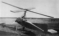
The C.4 was powered by an 80 h.p. Le Rhone rotary and was based upon the shortened fuselage of a Sommer monoplane.
9 января 1923г.: спроектированный испанцем Мануэлем де ла Сиерва, автожир С.4 Autogiro совершил первый успешный полет, преодолев 4-км круг на мадридском аэродроме "Cuatro Vientos".
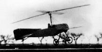
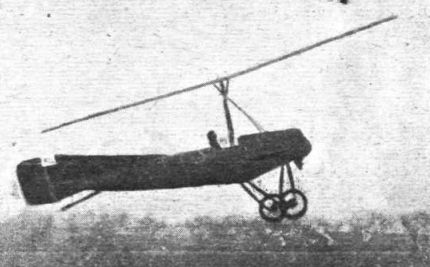
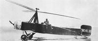
View of the "Autogiro" in flight.
The Cierva C-4, brainchild of Spaniard, Juan De La Cierva and his first demonstrably successful autogiro. It was completed at the end of 1922 and a month later took the aviation world by storm with a 4 kilometre, or 4.375 yard closed-circuit flight officially timed at 3 minutes, 30 seconds, representing a speed of 42.6mph, when flown by Flying Officer Gomez Spencer at an airfield near Madrid, on 31 January 1923. This at a time when what few helicopters there were would be pressed to achieve 4mph, Cierva had come to rotary wing design in 1919 unencumbered by any helicopter preconceptions. What Cierva was seeking was to produce an unstallable aircraft, that is, one that would continue to fly rather than to drop out of the sky should it be flown too slowly. It just so happened that he chose to exploit the properties of an autorotating rotor system. By this means the autogiro can descend back to earth at angles of up to 80 degrees, but land gently within a space of a few dozen feet at most. Initially troubled by the same instability problems that were besetting the aspirant helicopter developers, Cierva's non-driven rotor troubles proved far easier and quicker to tame. Indeed, his pioneering of the flapping and dragging rotor arm hinges was to solve many of the helicopter's longest standing problems at a stroke.
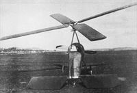
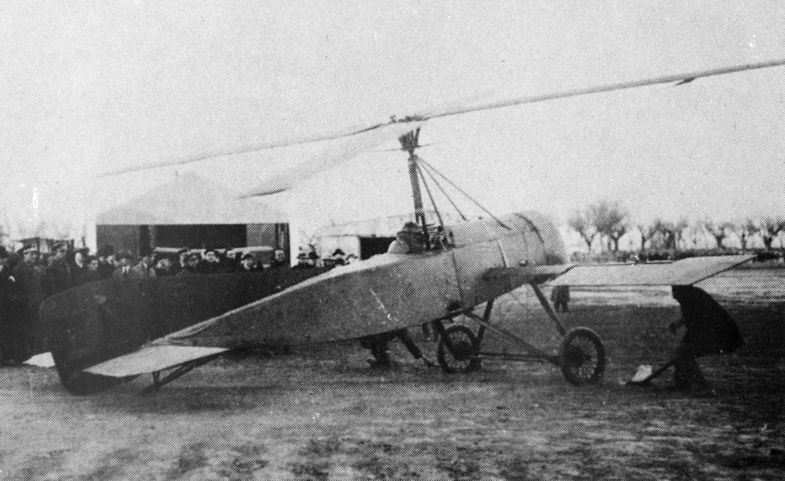
The C.4 at Getafe aerodrome, Madrid, in 1922. The rotor blades had a hinge which allowed them to “flap.”
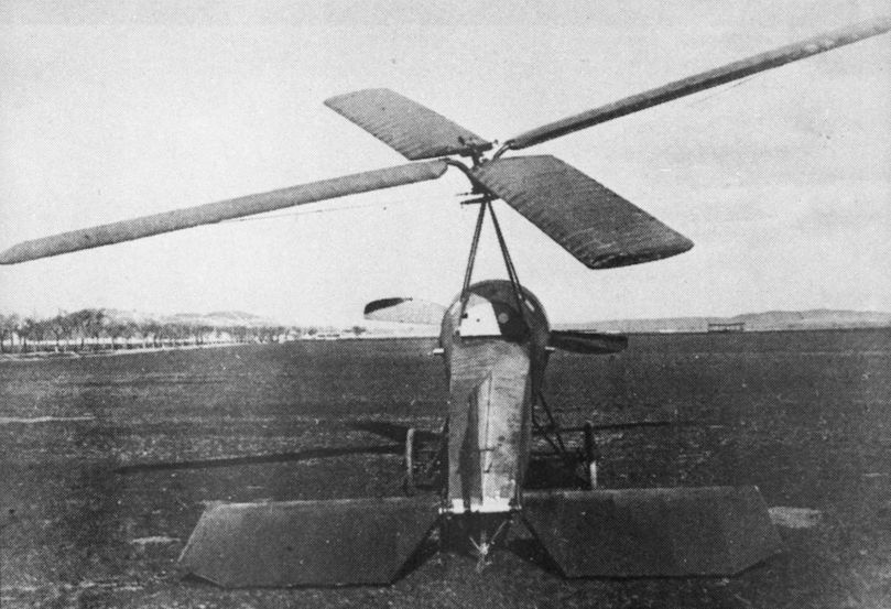
While still working on No. 3, Senor de la Cierva conceived the idea of stabilising his machine by hinging the blades to the axle, and this was done in No. 4, which is shown in Fig. 4. Lateral control was provided by tilting the axis of the windmill, but it was found at once that the pilot's strength was insufficient to work the controls.
In its final form, with a locked rotor head and ailerons on outrigger spars, it made the first successful autogiro flight on January 17, 1923.
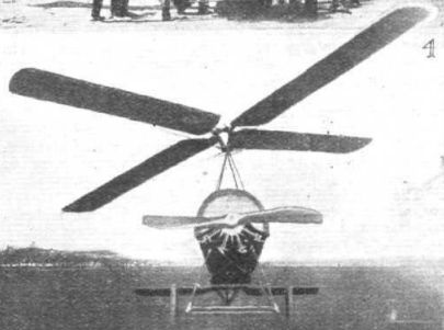
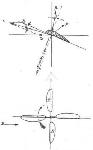
A rebuilt machine, shown in Fig. 5, was provided with two small non-lifting ailerons carried on streamlined spars, the windmill axis being rigidly fixed. The machine shown in Fig. 5 made several successful flights, the first being made on January 31, 1923, and being of four minutes duration.
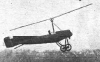
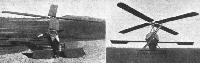
Rear and front views of the Cierva "Autogiro."
The first official demonstration of an autogiro took place at Getafe aerodrome on January 22, 1923, the C.4 being flown by Lt Alejandro Gomez Spencer.
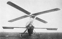
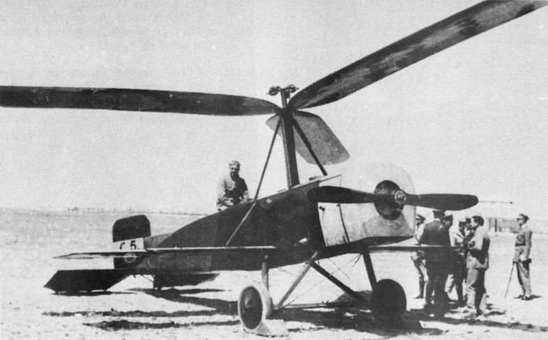
C.5
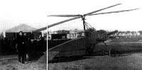
The C.5 at Cuatro Vientos aerodrome, Madrid, in 1923. It utilised the fuselage of the earlier C.2, having a 110 h.p. Le Rhone as its powerplant.
Autogyro No. 5,. shown in Fig. 6, incorporated the same principles, but improvements were effected in the detailed design. This machine had only three blades, and also made several successful flights. It was, however, damaged very badly while taxying. By this time the Spanish aeronautical authorities took over the further development of the Autogyro, three machines of the type 6 being built of which the third is that now being tested at Farnborough.
Pilot A. Spencer lounges on the fuselage of the short-lived C.5, which ended its life in a crash in July 1923.
 
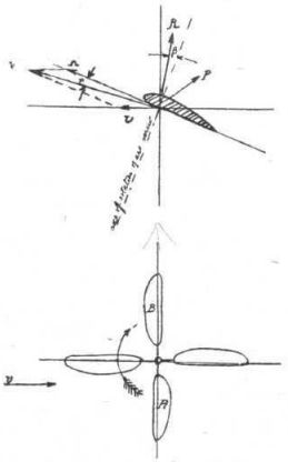
Diagram showing the forces in the lifting vanes.