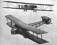
Lawson L-2 и L-4 Airliner
В 1920 году фирма "Lawson Air Line Company" из Милуоки, штат Висконсин, разработала и построила для собственных нужд большой гражданский биплан L-2. Стандартная загрузка составляла десять пассажиров, но в полете на небольшое расстояние на борту могли быть еще восемь человек, для которых предусматривались легкие откидные сиденья.
Два двигателя Liberty мощностью по 400 л. с. были установлены между крыльями по бокам фюзеляжа. Размах крыла составлял 27,74 м, максимальная взлетная масса - 5897 кг, максимальная скорость - 161 км/ч.
В 1924 году был спроектирован и построен еще более крупный самолет L-4.
Длина L-4 достигала 16,51 м (у L-2 - 14,63 м). В салоне L-4 оборудовали спальные места, кухню, имелись и другие удобства.
В составе силовой установки было три мотора, третий мотор установили в носовой части фюзеляжа. К сожалению, перед первым полетом машина сломалась - L-4 установили на мягкий грунт, и при попытке руления он получил тяжелые повреждения.
Вскоре после этой неудачи компания "Lawson" прекратила свое существование - L-4 разорил ее.
ТАКТИКО-ТЕХНИЧЕСКИЕ ХАРАКТЕРИСТИКИ
Lawson L-4
Тип: пассажирский самолет с возможностью ночных перевозок
Силовая установка: три ПД водяного охлаждения Liberty 12 Vee-12 тягой по 420 л. с. (313 кВт) каждый
Летные характеристики: ожидаемая максимальная скорость 177 км/ч
Масса: пустого 4427 кг; максимальная взлетная 8457 кг
Размеры: размах крыла 33,96 м; длина 16,51 м; высота 5,33 м; площадь крыльев 188,40 м2
Показать полностьюShow all
Flight, May 1921
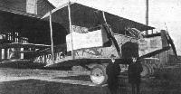
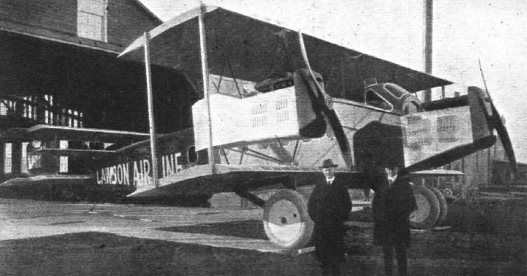
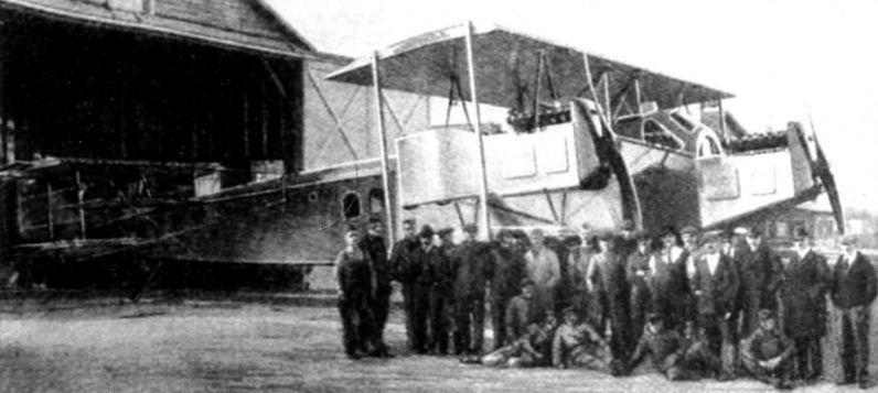
THE LAWSON MIDNIGHT AIRLINER
THE new Lawson Midnight Airliner which has recently been completed at the Lawson Airplane Company's plant in Milwaukee, Wisconsin, contains a large number of new features in aeroplane design and construction.
This ship, like all of its predecessors built by the Lawson Airplane Company, was designed by Alfred W. Lawson, who has already brought out eight distinct types of aeroplane design during the past five years, and it might be added here that all of the ships which Mr. Lawson designed and which were built under his direction have already met with considerable success.
This mammoth ship, which is designated in the series of airliners already having been built or now in course of construction by the Lawson Airplane Company, is technically known as the "L-4."
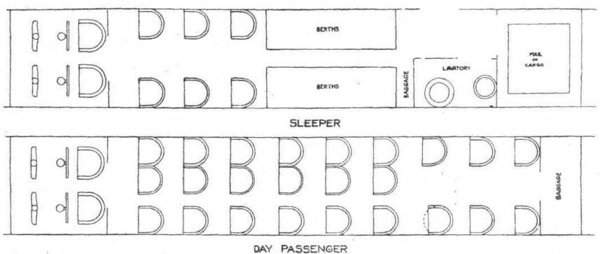
In designing the Midnight Airliner, Mr. Lawson brought out a ship which can be either used for passenger carrying or mail carrying purposes, and can also be changed from a night ship with sleeping berths to a day ship with chairs, within half an hour.
Some of the special features which the new ship contains and which might be particularly interesting to call attention to at this time are as follows: The captain and pilot's house, which is walled off separately from the general cabin, contains a collapsible seat for the pilot whereby he can either thrust his head out through an opening in the roof of the cabin and thereby have a clear and unobstructed view from the outside, or he can lower his seat a foot and a half and, by closing the aperture in the roof with a slide provided for the occasion, he can then be enclosed entirely within and see to steer the ship, through windows all round the pilot's cabin. There is a dual control in this cabin which is operated by both the captain, who will act as navigator, and the mate, who will act as pilot or steersman, as it were.
Besides having regular sleeping-berths for the passengers in the regular cabin, there is also a toilet-room which has all of the ordinary accessories of a Pullman railway car plus a shower bath, which Mr. Lawson has installed for the use of fastidious passengers who may want to pay an extra price for such a luxury!
Just back of the cabin is located the Mail Compartment, in which has been designed a mail chute whereby mail can be either put on or taken off while the machine is in flight. Passengers can also be taken on or put off through the same method, while the ship is in flight.
This is accomplished by a smaller machine flying up under the Lawson Airliner and running along at the same speed as the latter. A mail bag is lowered by a rope to the "under-'plane" and another bag of mail is taken on in exchange. A passenger can also be put off or taken on by this same process, and it is Mr. Lawson's intention during some of the early flights of the "L-4" to try-out both the taking-on and putting-off of mail and passengers by this method. [We think we will make the full journey, at present thank you !- ED.]
A more or less technical description of the Lawson Midnight Airliner is as follows :-
Fuselage. - The pilot's cabin is separated from the main cabin by a double hinge door in which is placed a beveled glass window so that either pilot or navigator may see into the passenger cabin or vice versa, and also talking tubes are placed through this door so that the captain or pilot may talk directly to the engine man and mechanic who sits in the first seats of the regular cabin.
In front of the controls is a mahogany dashboard equipped with a complete set of instruments, such as three sets of Delco Boosters, tachometers, oil pressure gauges, and water and oil thermometers. There is also a clock, barometer, air speed indicator, vertimeter, lateral and longitudinal inclinometers. A word might be said of the tachometers. Due to these being installed on the dashboard in the pilot cabin, the shafts that run to the engines are attached to right-angle reduction gears, which drive the long shaft one-fourth crank shaft speed, a large factor in preventing shaft whipping or breakage where directions of drive take place. These shafts as well as the air, oil and water thermometer lines, run through streamline cases between the body and the nacelles.
Between the pilots, and mounted on top of an aluminium pedestal, are the throttle levers, so arranged that any one or all motors can be controlled at the same time. On the face of this pedestal and about 4 inches as below the top is a hand wheel for operating the trimming plane. The throttle controls are positive throughout the entire system, being composed of steel tubing, which rotate or push and pull, as the case may be.
Dep. control is used. Instead of the usual chain drive, bevel gears rotate a vertical shaft running through the main column, which has a pinion at the base driving a rack. On the outer ends of each rack the aileron control cables are attached, these running directly out to the wings after passing over large directional pulleys.
The elevators are operated by doubled cables running under the floors on the left side of the body, to a rocker shaft placed on the top longeron in back of the cabin. Several inspection doors are placed on the floor of the cabin for these as well as the rudder cables, which also are arranged similarly to the elevator control cables.
On a separate dashboard overhead and between the pilots are placed the switches. Near the seats are placed fire extinguishers.
A mechanic dashboard is placed in the front end of the main cabin on the right side. This is equipped with air pressure gauges and an air distributor tank into which the air is pumped from the engines, for the air pressure petrol system, and properly distributed to the respective petrol tanks. This tank is always primed, so it is an easy matter to start all three engines. Alongside of the dashboard are the ignition control handles for advance and retard, there being push and pull rods to all motors.
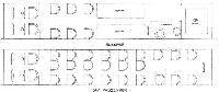
The cabin itself is of the convertible type, having attachments for twenty-six seats, berths and mail compartments. When used as a day machine all twenty-six seats are installed, and when used as a sleeper there are six seats and berths. These latter are of the disappearing type, and can be extended within a few minutes. The machine carries a complete lighting system for dashboard, cabin lights, wing and tail lights, and a large search light and a heating system. At the rear end of the cabin, and on the right side of the machine is located the main entrance door. Directly across from this door on the right side of the machine is a complete bathroom, the first ever installed upon any aeroplane. There is a shower bath, washstand and towels, mirror, drinking water and lavatory. A large overhead water tank of both hot and cold water is used for the shower, while the tank containing ice water is used for drinking purposes. The whole compartment is white enamelled, with white rubber draw-curtains on the windows and entrance, while the floor is tiled.
Behind the bathroom is a mail chute and baggage room. This is reached through a door which also allows entrance for inspection of the rear end of the body. An inspection walk runs from this door to the stern.
Constructionally the body is composed of spruce longerons the entire length. These are pin jointed at the front allowing a complete removal of the whole front engine with its control and attachments, radiators, etc. The longerons are again jointed immediately behind the rear end of the cabin, thus allowing the whole tail to be removed and a new one installed, thus facilitating little wastage of time in making repairs.
The complete cabin section is composed of laminated spruce bulk heads with the grain of the wood running according to the direction of the loads, thus allowing greatest strength for least weight. The cabin is completely covered with veneer with light stiffening pieces. The windows are of safety glass while those in the pilot cabin are of celluloid due to the convex curves of this section. The rear end of the fuselage is standard construction, having spruce struts and cable bracing, and is linen covered. At the extreme rear end and around the tail plane and tailskid section the body is again covered with veneer to stiffen this portion and prevent twisting.
The interior of the cabin is finished in mahogany and cream, and is covered with a heavy green brussels carpet, while the outside is enamelled green throughout.
When used as a mail machine, mail compartments are installed in place of all but six of the usual passenger seats, thus allowing passenger carrying as well as mail and cargo. This is the only change found necessary for this conversion.
Wing Structure. - There are five sections in the upper and four on the lower, each hanging to the other and to the body. They are of the usual construction, consisting of two spars of I-section spruce, and laminated in two pieces with hardwood strips top and bottom. The ribs are of the girder type, and are of spruce material throughout. All ribs are of standard section, there being no special ribs in the whole structure. Square spruce struts carry the compression. The engine section panels have internal wires in both directions, while all other panels are of 3/16-in. cable doubled for drift loads and single for trueing. The lift cables are double and the landing cables single. Large balanced ailerons are used top and bottom, and are connected by streamline tubing instead of wires, thereby eliminating continual care and attention. Celluloid inspection doors are placed at all aileron control cable pulleys on the lower wings. Spruce struts of streamline section are used externally. All cable strut fittings are of the internal type, concentrating all loads on the neutral axis of the spar. As in the body and other parts, these fittings are chrome vanadium steel, heat-treated and zinc-plated, giving an enormous strength for their weight. On each end of the wings and under the outer struts are ash wing skids which are sprung by rubber shock-absorber cord covered by an all-metal streamline case. To the skid is hung a tube which telescopes into another tube mounted on a ball-and-socket joint to the rear spar. The front end of the skid is hinged to a fitting on the spar, while a diagonal tubing rakes the side action. The wings are linen covered and coated with clear varnish. The factor of safety is six throughout.
Empennage. - This is of biplane type, having balanced elevators and three rudders, the outer two of which are also balanced. In front of the rudders are vertical fins. The construction is similar to the wings. To relieve the weight of the elevators upon the pilot controls these are equalised by rubber absorbers attached to a lever upon the rocker shaft in the rear end of the body. The elevators are also connected together by tubes like in the aileron system. The vertical fins are provided with adjustable screws on the top of the front ends, thus allowing the top tail plane to be set to any required angle.
A trimming plane is installed just ahead of the tail plane, which can be adjusted in flight from the pilot cabin by a wheel before mentioned. This is worked by a screw and trunnion, so the setting is at all time positively locked in position. All vertical surfaces are enamelled green, while the horizontal surfaces are finished similar to the wings.
Landing Gear. - Four large Palmer wheels of 1,250 mm. by 250 mm., or 49 by 10, and streamline cased, compose the main landing gear. These are placed upon short axles of high grade steel tubing, which in turn are slid over cast steel elbows on the inner ends. This elbow is fixed to heavy compression tubes running up to the body, and are pinned there. The Vee is of triangular shape made of laminated spruce with the grain of the wood arranged as in the body bulkheads. On each side of the apex of the Vee are the rubber absorbers placed in line with the Vee. The nose and tail of the shock-absorber brackets are cased with streamline fairings. The tail skid is rubber absorber sprung, and is universally mounted to the body by four steel tubes. In case of failure of any part of this member the machine will fall upon a streamline bumper secured permanently to the sternpost.
Nacelles. - On each side of the body and between the top and bottom wings are placed the nacelles. These are of spruce longerons, laminated bulkheads and struts, braced by 3/16-in. cables. The engines are directly behind laminated spruce nose pieces having vents for air circulation. The nacelles are completely covered with aluminium excepting the nose pieces, and all sides excepting the bottom are provided with large doors. The petrol tanks in the rear end of the nacelles are protected by an aluminium fire-plate. The bottom of each nacelle is formed to a well shape where oil and refuse may collect and drain out through pipes. The oil tanks are placed alongside of each engine, and where they will receive a certain amount of cooling as well as allow a small amount of piping. Both engines are equipped with carburettor stacks, which direct back firing out and away from the nacelles or tanks. Long exhaust pipes help to direct any flames away also, as well as to deaden the noises and carry any oil from the exhausts away from the machine completely. Inserted in the entering edge of the top wing are water header tanks. These are connected to the engine water outlet and radiator inlet pipes through large pipes which also help to cool the water due to their exposure to the air. On either sides of the nacelles and behind the engines are the radiators suspended on steel tubing and brackets. Although, perhaps, rather small, they have been installed in this position after careful experimenting and tests which indicate this position the best for cooling purposes. All radiators are equipped with shutters on the rear side, these being operated by levers in the cabin. Each pair of radiators being connected together can be worked independently from any motor desired.
The centre engine, as before mentioned, is mounted on a detachable nose. The nose piece is similar to the nacelle nose piece as in the cooling. It is also equipped with carburetor stack and the same system of radiators. The fuel tank for this engine is under the pilot cabin. It will thus be seen that each motor has its separate petrol system thereby eliminating considerable trouble in case of a leak. All pipes and wiring are marked with the standard specifications identification colours to allow quick inspection, repair or assembly. The oil tank is alongside of the motor, thus again allowing the use of short piping. An aluminium fireplate attached directly to the bulkhead, also separates the engine from the cabin.
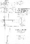
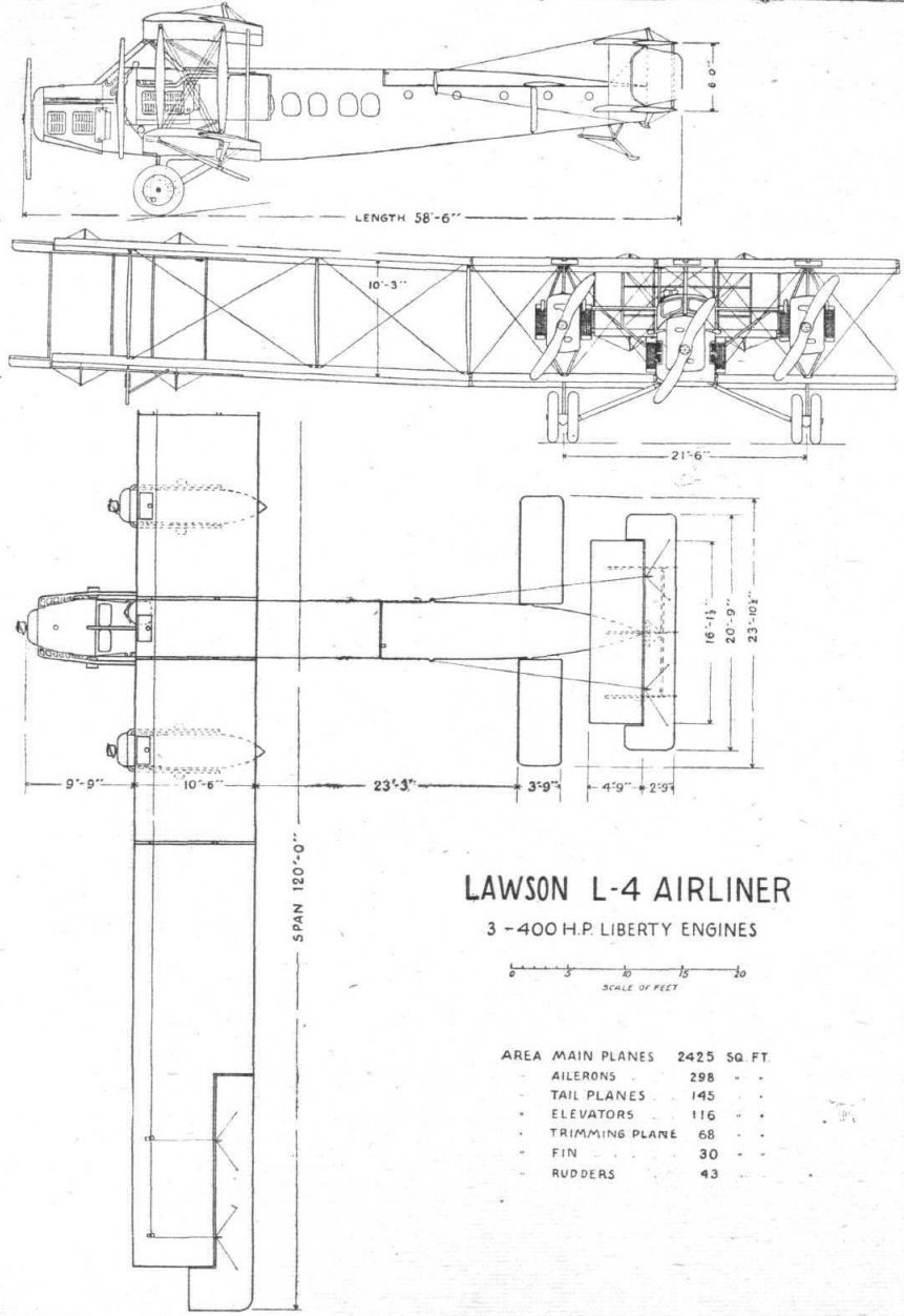
Other characteristics and the principal dimensions of the Lawson Midnight Airliner are as under :-
Span 120 ft.
Overall length 58 ft. 6 ins.
Overall height 18 ft.
Wing section U.S.A. 5.
Chord 10 ft. 6 ins.
Gap 10 ft. 3 ins.
Upper wing area, including ailerons 1,250 sq. ft.
Lower wing area, including ailerons 1,175 sq. ft.
Total aileron area 298 sq. ft.
Total stabiliser area 145 sq. ft.
Total elevator area 116 sq. ft.
Trimming plane area 68 sq. ft.
Total fin area 30 sq. ft.
Total area of rudders 43 sq. ft.
Power Plant
Three standard Liberty's, 400 h.p. each, 1,700 r.p.m. 1,200 h.p.
Three propellers, 10 ft. dia. 6 ft. 6 ins. pitch, fuel consumption of each motor at 1,700 r.p.m., 5 lb. per h.p. hr. 36 gal. hr.
Oil consumption of each motor at 1,700 r.p.m., .0373 lb. per h.p. hr. 2.13 gal. hr.
Fuel consumption of three motors 108 gal.
Oil consumption of three motors 6-39 gal.
Nacelle fuel tank capacity (2) 490 gal.
Centre engine main fuel tank capacity 149 gal.
Centre engine auxil. tanks (2) 94 gal.
Total fuel capacity 733 gal.
Total oil tank capacity 58-2 gal.
Total capacity of three overhead water tanks (3) 18 gal.
Weight Distribution and Performance
Structural weight, including wings, fuselage and nacelles complete, trimming plane, control surfaces, and landing gear 7,434 lbs. '
Power plant, including water and tanks, petrol tanks, piping and wiring, exhaust manifolds, nacelle tanks, propellers and radiators 4,560 lbs.
Fuel and oil 4,589 lbs.
Passengers, baggage and mail (as mail machine) 3,570 lbs.
Passengers, baggage and cargo (as passenger machine) 4,360 lbs.
Total weight, mail, 21,462 lbs.; passenger, 22,820 lbs.
Best ang. of glide, 1 in 16-9 at 60 m.p.h.
Endurance at full power (ground level) at 108 gal.hr. 6-78 hrs.
Endurance at cruising speed at 6,000 ft. 11 hrs.
Maximum speed 112 m.p.h.
Cruising speed 70 m.p.h.
Landing speed 53 m.p.h.
Range 800-825 miles.
Service ceiling 22,000 ft.
Показать полностьюShow all


 Wiki
Wiki