

Описание
Страна : Великобритания
Год : 1923
Единственный экземпляр
Варианты
- Nieuport - Nieuport-10 - 1915 - Франция
- Nieuport - Nieuport-12 - 1915 - Франция
- Aircraft Disposal Co (ADC) - Variable Camber Monoplane - 1923 - Великобритания
Flight, March 1923
A VARIABLE CAMBER MONOPLANE
An Interesting Aircraft Disposal Co. Experiment
IT is now fairly generally agreed that no great progress is to be expected in the design of fixed-section aeroplane wings. Small improvements may result from further experiment, but if any marked gain in efficiency is to be attained it is admitted that we shall have to look to wings of other than fixed section and fixed area. An increase in lift can, of course, be obtained in many ways. One method is by increasing the wing area for slow speed, decreasing it for high speed. The structural difficulties are very great. Then there is the slotted wing invented by Handley Page, in which the "burble point" is made to occur much later, i.e., at a higher angle of incidence, and consequently a greater lift is obtained. Extraordinarily great increases in the lift have been obtained in this way. An alteration in camber is known greatly to affect the lift, and by the use of a hinged trailing edge, as in the Fairey machines, the wing camber is virtually altered, the lift varying with the camber. This system also has given excellent results, not only in lift variation but in control at large angles. There are those who maintain, however, that the sharp break in a wing section which occurs with a hinged trailing edge cannot be as efficient as a wing in which the curves of the section are as smooth at maximum camber as they are when the wing is flattened out. While that is probably true, the mechanical difficulties are considerably greater than those involved in the hinged-trailing-edge type of wing, and although several examples of variable camber wings have been produced, no really satisfactory wing of this type has yet been evolved.
The Aircraft Disposal Co. have recently secured a design in which the camber is varied smoothly by means of flexible wing ribs. An experimental machine incorporating this feature arrived at the Waddon factory some weeks ago, and we understand that flying tests will be carried out shortly. The machine is stated to have been flown by the original makers, but the A.D.C. desire to carry out thorough tests of their own before finally deciding on the merits of the design. In the description which follows it should be borne in mind that the machine is purely experimental, and that it contains features which would not be perpetuated in later types, should the Aircraft Disposal Co. decide to take it up.
Fundamentally, the variable camber monoplane consists of the fuselage of a French Nieuport "one-and-a-half" plane of the type popular during the War, supported by a thick tapering parasol wing. It was probably chosen because it happened to be of about the right size, and was available at the time the inventor of the wing wished to make full-size flying tests. Thus it is not to be regarded as a permanent portion of the design, but merely as a sort of full-scale "laboratory" for the testing of the wing. That being the case, and the Nieuport having been described in detail in FLIGHT during the War, there is little need to refer to the details of it. The same applies to the under-carriage, and to a certain extent to the tail, the only departure appearing to be a slight increase in the size of the latter.
The wing is of interest owing to the principle employed of securing the ribs to the front spar only (which is very deep), the function of the rear spar being mainly to form a member of the internal drag bracing.
The trailing portion of the ribs is supported on two tubes, hinged at their outer ends to a stout box rib, and at their inner ends to a rocking crank. This crank is operated by pull and push rods springing from cranks inside the fuselage. The upper rib flanges are secured to one of these tubes and the lower flanges to the other. The rib to which the outer ends of the camber tubes are hinged occurs in line with the inner end of the ailerons, and as the tubes take their fulcrum at this point it will be seen that the outer portion of the wing does not have its camber altered, while the central portion has its camber progressively changed as the centre-line is approached. Thus the inner portion of the wing, where the chord is greatest, receives a maximum of change, while the tips remain unaffected. While this may to a certain extent reduce the effectiveness of the camber gear, it facilitates construction, and with the tapered wing the central portion, which includes the maximum area, is mostly affected.
The wing is mounted above the fuselage on struts, and it will be seen that, whereas there are struts directly supporting the front spar, the rear spar is supported indirectly by a channel-section steel member of triangular plan form, against the sides of which the roots of the rear spar abut. The accompanying diagrams should make the principle clear, and as it is highly probable that the details will be altered in later machines, we have not thought it of any interest to publish sketches of the particular manner of giving effect to the fundamental principle.
The wing construction appears to be open to criticism on account of the method which has been adopted of stitching the top fabric to the top flange only, and not through to the lower flange. This was, however, necessary in order to enable the wing to change its thickness simultaneously with the change in camber. The effect of the camber gear is to change the section in the centre from a flat-bottom camber, thick-section, to a thinner, deeply cambered section. As this is what is required (thick wings with flat or convex bottom camber having a low lift and a high value of L/D, while thin deeply-cambered wings have a high lift coefficient but a relatively inferior L/D), it may be expected that the wing will give extra speed range, although to how great extent yet remains to be seen.
In the meantime, the machine, as already stated, is being overhauled at Waddon, and Major Grant is having it strengthened up wherever it seems to him to require it. The machine arrived without engine, and an engine from the large stocks of the A.D.C. is being put in, probably a Clerget or le Rhone. It will be interesting to learn the results of actual flying tests, and should these be promising it is easy enough to visualise detail improvements upon what is, after all, but a relatively crude experimental wing, built as cheaply as possible in order to test an idea.
- Flight, March 1923
A VARIABLE CAMBER MONOPLANE
Фотографии
-
Flight 1923-03 / Flight
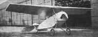
Three-quarter front view of variable camber monoplane.
-
Flight 1923-03 / Flight
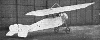
Three-quarter rear view of variable camber monoplane.
-
Flight 1923-03 / Flight
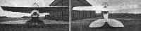
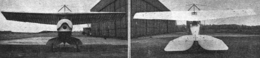
Front and rear views of variable camber monoplane.
-
Flight 1923-03 / Flight
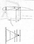
Section and plan of the spar supports, operating cranks etc., of the variable camber wing.
-
Flight 1923-03 / Flight
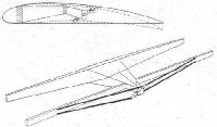
Diagrammatic perspective view of the camber-operating tubes, spars, etc., of the variable camber wing. The upper diagram shows the manner in which the camber and section are altered. For high speed the section is thick and flat, for slow speed it is thin and deeply cambered.
-
Flight 1923-03 / Flight
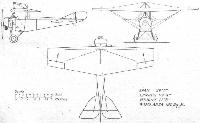
General arrangement drawings of the variable camber monoplane with which the Aircraft Disposal Co. is now experimenting.


- Фотографии