
 Wiki
Wiki Flight, September 1926
THE CRANWELL LIGHT AEROPLANE IV.
An Interesting Training Machine Built by Amateurs
IN view of the fact that this year's Cranwell light aeroplane, designed by Flight-Lieut. N. Comper and built by members of the Cranwell Light Aeroplane Club, was based mainly on the Pobjoy engine, a few words concerning this engine may serve to explain in many respects the reasons underlying the fundamental design of the C.L.A. IV. Designed by Capt. Pobjoy, the "P" engine, as it is called in the entries list, is a seven-cylinder radial air-cooled engine of extraordinarily low power-weight ratio. Without going into details we may say that Capt. Pobjoy has been guided in the design of this engine by the principle that all parts subject to heavy loads of one sort or another should be very substantially built, while so far as possible there should be no parts which were not contributing to the work of the engine, all helping to "pay their way." The result has been an engine differing in many respects from orthodox practice, but achieving a maximum horse-power of 65 b.h.p. for the astonishingly low weight of 100 lbs., this figure including the weight of two magnetos. Coupled with this light power-weight ratio, the engine has the advantage of very low fuel consumption, the actual figure being just over 0-5 pint/h.p./hour. It is hoped that later on there may be an opportunity of describing this very interesting engine in detail. For the present, space does not permit of doing so, but in order thoroughly to understand the Cranwell machine it is essential that one should bear in mind that its design was based on the "P" engine. We are quite sure everyone will sympathise sincerely with Capt. Pobjoy and the Cranwell Light Aeroplane Club when we point out that it seems extremely unlikely that the engine will take part in the Lympne competition. This is due to the fact that in the course of the type tests at Farnborough a breakage occurred which, although due to a cause which in itself was quite trivial, will nevertheless have the effect of preventing the type tests being passed in time for the machine to take part in the competition. We are quite convinced that the engine will pass its type tests in the near future, but in the meantime the failure is a very serious blow, not only to Capt. Pobjoy and those associated with him, but also to the Cranwell Light Aeroplane Club, who will be deprived of one of the two machines entered for the competition.
The two machines entered by the Cranwell Light Aeroplane Club are identical except for the engines, the power plant fitted in the second machine being a Bristol Cherub, Series III. In the design of this machine Lieut. Comper had in mind not only a two-seater aeroplane suitable for collecting points in the competition, but also a machine which should prove a practical training machine afterwards. As the general arrangement drawings will show, the machine is of somewhat unorthodox design as regards the arrangement of its wings, having a top plane of considerably smaller chord and span than those of the bottom plane. There were various reasons for choosing this arrangement, which may possibly be very slightly less efficient aerodynamically than the more orthodox arrangement of an unequal span biplane in which the top plane has the larger area. Chief among these was the desire to provide a good view from both cockpits. With the arrangement chosen the small chord of the top plane has enabled Lieut. Comper to place the front cockpit ahead of the top plane and the rear cockpit behind it, so that from either cockpit the view upwards is not obstructed to any serious extent, and this has been effected without necessitating the usual cut-out portion in the trailing edge of the top plane, which probably has some effect on aerodynamic efficiency. The fact that there are no ailerons on the top plane also results in a certain amount of saving in drag, while from a structural point of view the short free length of the top spars is, of course, an advantage, in that it permits of a not inconsiderable saving in weight.
The single I-struts which connect top and bottom planes are of special construction, and have at the top and bottom of the I special sheet steel fittings sandwiched in between the two layers, these fittings being hinged to corresponding fittings on the main wing spars. The wing section employed in both top and bottom planes is that known as R.A.F. 31, but a slight modification to the original section has been made by symmetrically reducing the ordinates about the neutral chord, as it was not considered that it would be structurally economical to use the full depth of the original section. The main wing spars are of spruce spindled out to an I-section, and the spruce ribs are of usual Cranwell construction. The centre section struts are in the form of steel tubes with wood fairings, and the top centre section itself contains the main petrol tank, as it was feared that with the higher position of the carburettor in the Series III Cherub, a sufficient head of petrol might not be obtained if the tank were placed in the deck fairing of the fuselage.
For the purpose of the Lympne competition the wings are made to fold, although it is not considered that for a machine of this size it is really essential that this feature should be incorporated.
As already mentioned, ailerons are fitted on the lower wing only, and the operating cranks are placed on top of the wing in order to avoid the risk of damage by contact with the ground and the necessity of wing tip skids. The flaps have a differential action obtained in the usual manner by the angle of the control crank which operates them.
The fuselage of the C.L.A. IV is similar in form to, although slightly larger than, that of the C.L.A. III monoplane. The rear portion is in the form of a Warren girder as regards the sides, while the top and bottom bracing are of "N" formation. The longerons are of ash in front and of spruce at the back, and the diagonal struts in sides, top and bottom are square-section spruce at the ends, turned to a circular section over the greater length. The attachment to the longerons is by means of three-ply gussets, the shape and arrangement of which are illustrated by a sketch. This form of construction is carried from the stern-post up to the rear cockpit, where the structure changes to the more orthodox one of rectangular panels braced diagonally by wire. A curved deck built of light formers and stringers rounds off the top of the fuselage.
The two cockpits are quite roomy, and as already mentioned the view obtained from both is excellent. The dual controls are of somewhat unusual type as regards the stick. This is forked to a longitudinal rocking shaft which operates the wing flaps, but passes up through a "gate," from which the elevator is operated, the stick sliding in this "gate" laterally and also to a slight extent in a vertical direction owing to the difference in centres between the stick pivot and that of the gate. The rudder control is in the form of the usual foot-bars of steel tubing.
The Cherub engine is mounted on a sheet-steel plate similar in shape to that used in previous Cranwell machines, which has been found to answer the purpose well and to be quite light. For details of this engine mounting we must refer readers to a description of previous Cranwell machines, in which this feature has been illustrated. The oil tank is placed immediately aft of the engine, while the petrol tank, as already stated, is contained in the top centre section. A Fairey-Reed duralumin propeller is fitted.
The undercarriage of the C.L.A. IV is in the form of two V's bent up from small diameter light gauge steel tubing, with a through axle and the usual rubber cord shock absorbers. The rear legs of the undercarriage are attached to the wing roots of the lower plane, which are built integral with the fuselage and project some distance past the sides of the fuselage in order to give clearance for the trailing edge of the bottom plane when the wings are folded. These wing roots are built up from very substantial spruce spars of considerable depth, but in the covering the detrimental effect of such deep spars is largely overcome by careful fairing. The tail skid is similar to those used on the Bristol "Brownies," and is in the form of an immovably fixed laminated steel spring.
The fixed tail plane is of steel tube construction, as is also the rudder, while the fin and elevators are of normal wood construction.
On our visit to Cranwell last week we had an opportunity of seeing the club members hard at work, and it was most gratifying to observe the keenness of everybody concerned. Flight-Lieut. Comper has, of course, had the heavy task not only of designing the machine in his spare time, but of seeing to the correspondence of the club, and anyone at all familiar with the amount of work required in designing even a small aeroplane will appreciate that to do this as a spare time job is a heavy tax on a man's strength, both physically and mentally. Among the club members working on the machine were many N.C.Os., some of whom had agreed to forego their summer holidays in order to get the two machines ready for the competition. That the club should be deprived of one of its machines in the competition is a piece of extremely bad luck, with which we are sure everyone will sincerely sympathise.
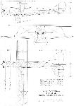
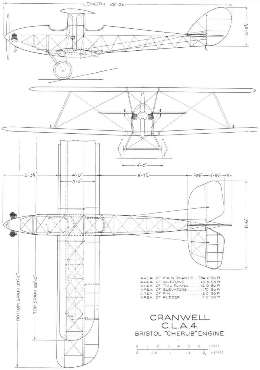
The main dimensions of the C.L.A, IV are given on the general arrangement drawings published on page 549. The weight of the machine empty is 480 lbs., and the total loaded weight 860 lbs., so that the wing loading is 5-25 lbs. per square foot, and the power loading 25-3 lbs. per h.p. We hope to publish photographs of this machine next week.
British Light ‘Plane Development & Lympne Meeting
THE 1926 MACHINES
No. 11. The Cranwell C.L.A. 4 (Pobjoy Engine)
One of the minor tragedies in connection with the 1926 Lympne meeting has been the mishap to the Pobjoy engine which was to have been fitted in one of the two Cranwell biplanes entered. This engine, which develops a maximum of 63 b.h.p. for a weight of only 100 lbs., was being type tested at Farnborough when a certain part broke. The breakage was in itself quite a trivial affair, and should not be in any way due to the very high power-weight ratio of this engine. It was, however, sufficient to prevent the engine from passing its type tests in time for the competition, and, consequently, the machine in which it was to have been fitted has had to be scratched. This is all the more regrettable as there is every reason to believe that with the Pobjoy engine the C.L.A. 4 would have been in a position to obtain a very high ratio of useful load to fuel consumed. The engine is very economical, and the fact that it is of the geared type should have enabled the machine to do the get-off test quite easily, owing to the good propeller efficiency that might have been counted upon.
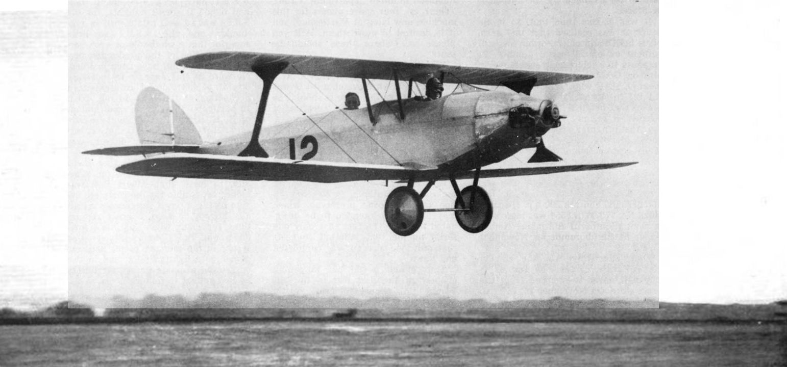
No. 12. The Cranwell C.L.A. 4 (Bristol "Cherub" Engine)
The second Cranwell machine, identical with No. 11, except for its engine, entered by the Cranwell Light Aeroplane Club, was described and illustrated in FLIGHT last week, and there is thus no need to give a detailed reference to it here. Suffice it to point out that the machine is chiefly remarkable for the fact that its top plane is of smaller span and chord than those of the bottom plane, a biplane arrangement not usually seen on British machines, although fairly frequently on Italian biplanes. The reasons for the arrangement, in the case of the Cranwell machine, are that it gives a good view from both cockpits while structurally it is advantageous on account of the shorter free length of top spar which it gives.
The C.L.A. 4 was designed by Flight-Lieut. N. Comper, and built by members of the Cranwell Light Aeroplane Club. It will be piloted in the competition by its designer, and all wish this plucky amateur effort every success. The transference of the Boys' Wing from Cranwell to Halton may seriously affect the future of the club, and we understand that Lieut. Comper is being transferred to the Felixstowe air station. Perhaps, however, one may hope for an amalgamation of the Cranwell and Halton clubs.
- Flight, September 1926
THE CRANWELL LIGHT AEROPLANE IV.
Фотографии

-
Flight 1926-09 / Flight
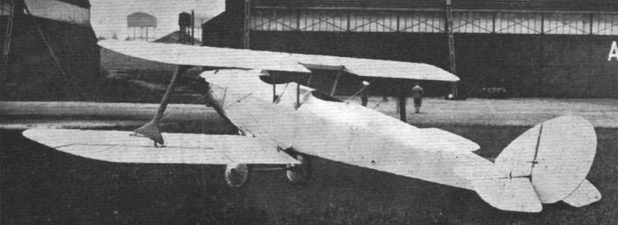
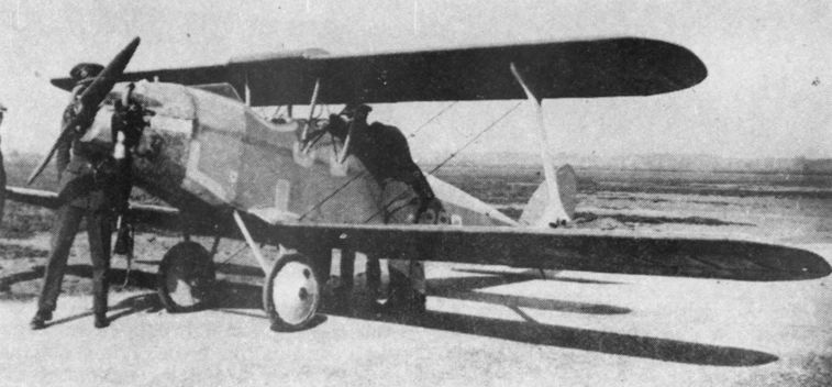
No. 12. THE CRANWELL C.L.A.4: Three-quarter rear view.
-
Flight 1926-09 / Flight
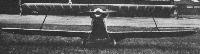
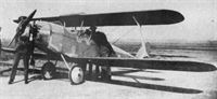
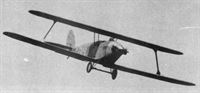
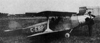
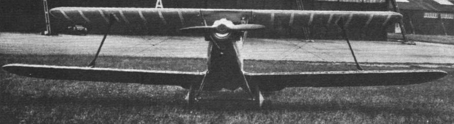
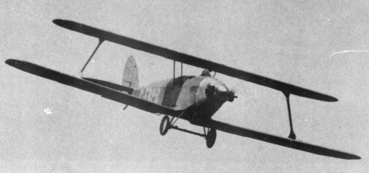
No. 12. THE CRANWELL C.L.A.4: Front view. Note the short top plane
-
Aeroplane Monthly 1978-12 / R.Riding - Cranwell C.L.A.4 /British pre-war ultralights/
Регистрационный номер: G-EBPB [4] The C.L.A.4A G-EBPB apparently engined with an ABC Scorpion in place of the Bristol Cherub.
-

Flight 1926-09 / Flight
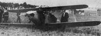
One of the "Eliminated": The Cranwell C.L.A.4 biplane damaged an undercarriage and was refused permission to repair. It is therefore out of the competition.
-
-

Aeroplane Monthly 1978-12 / R.Riding - Cranwell C.L.A.4 /British pre-war ultralights/
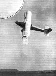
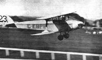
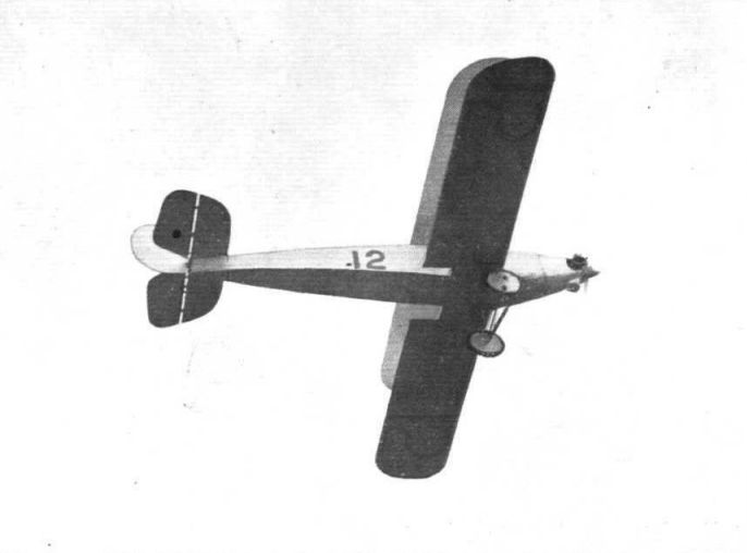
The flying view shows the C.L.A.4A being put through its paces at the 1926 Lympne Trials.
-
Flight 1926-09 / Flight
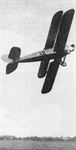
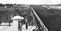
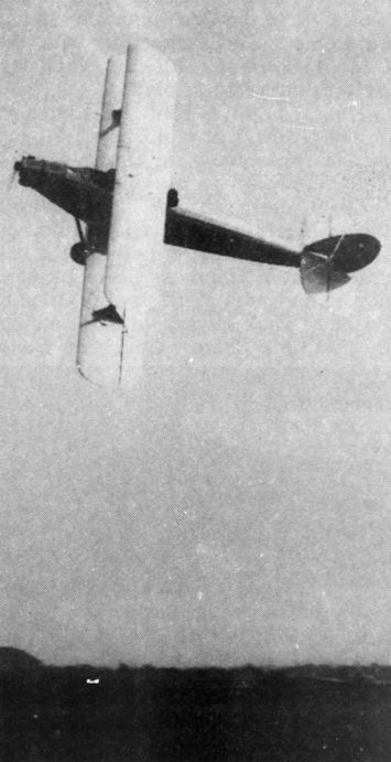
"BANKING ACCOUNTS" AT LYMPNE: 5. Lieut. Walmesley rounding the aerodrome turning point on the Cranwell biplane.
-
Aeroplane Monthly 1978-12 / R.Riding - Cranwell C.L.A.4 /British pre-war ultralights/
Регистрационный номер: G-EBPB [4] The inverted sesquiplane layout of the C.L.A.4A is well shown here.
-
Flight 1926-09 / Flight
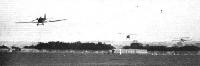
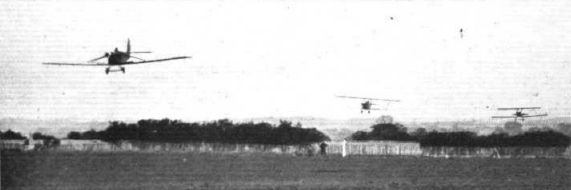
THE RACE FOR THE GROSVENOR CHALLENGE CUP: No less than 21 machines faced the starter for this race, a record number. The result was that machines frequently got bunched together at the turning points. Our photograph show one of some such incidents. In 1 are seen the D.H. 53, the Farnborough "Cygnet," and the Cranwell biplane approaching the aerodrome turning point.
Другие самолёты на фотографии: De Havilland Humming Bird / D.H.53 - Великобритания - 1923Hawker Cygnet - Великобритания - 1924
-

Flight 1926-09 / Flight
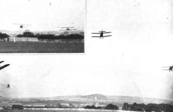
THE RACE FOR THE GROSVENOR CHALLENGE CUP: No less than 21 machines faced the starter for this race, a record number. The result was that machines frequently got bunched together at the turning points. Our photograph show one of some such incidents. 2, shows the wing tips of the Cranwell, the Hawker "Cygnet," the Blackburn "Bluebird," and one of the D.H. "Moths" heading for the Postling turning point.
Другие самолёты на фотографии: Blackburn Bluebird / L.1 - Великобритания - 1924De Havilland Genet Moth - Великобритания - 1926Hawker Cygnet - Великобритания - 1924
-
Flight 1927-04 / Flight
FINISH OF WINTON HANDICAP: In the lead is Ragg on the Farnborough Hawker "Cygnet" flying low. He repeatedly flew between the white rails and the enclosures. Behind him is Comper on CLA4. In the original photograph four more machines can be seen in the background, approaching the finishing line.
Другие самолёты на фотографии: Hawker Cygnet - Великобритания - 1924
-

Aeroplane Monthly 1978-12 / R.Riding - Cranwell C.L.A.4 /British pre-war ultralights/
Flight-Lieut. Comper winning the Stewards' Handicap on the Cranwell C.L.A.4 (Bristol "Cherub"). Average speed 70-85 m.p.h.
C.L.A.4 designer Flt Lt Nick Comper winning the Stewards Handicap at the Lympne Trials, September 1926. -
Flight 1927-06 / Flight
Регистрационный номер: G-EBPB [4] "Like Old Nick": Comper on the C.L.A.4 crossing the finishing line very low.
-
Aeroplane Monthly 1978-12 / R.Riding - Cranwell C.L.A.4 /British pre-war ultralights/
Регистрационный номер: G-EBPB [4] C.L.A.4 at the Orly meeting in September 1928, where it sustained damage to the undercarriage
-
Flight 1928-09 / Flight
FOLDING TESTS AT ORLY: Our machines showed superiority in the folding tests at the French Light 'Plane Trials. (5) Flight-Lieut. "Nick" Comper carries on in spite of his disheartening troubles with the C.L.A.4
-
Flight 1926-09 / Flight
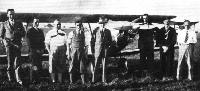
THE CRANWELL TEAM: Left to right, Flight-Sergt. Hammond, Flight-Sergt. McKeown, F.O. Cashmore, Flight-Lieut. Pack, Flight-Lieut. Comper (designer and pilot), Flight-Lieut. Walmesley, (pilot), Flight-Lieut. George, and F. O. Herbert.
-
Aeroplane Monthly 1978-12 / R.Riding - Cranwell C.L.A.4 /British pre-war ultralights/
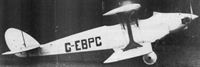
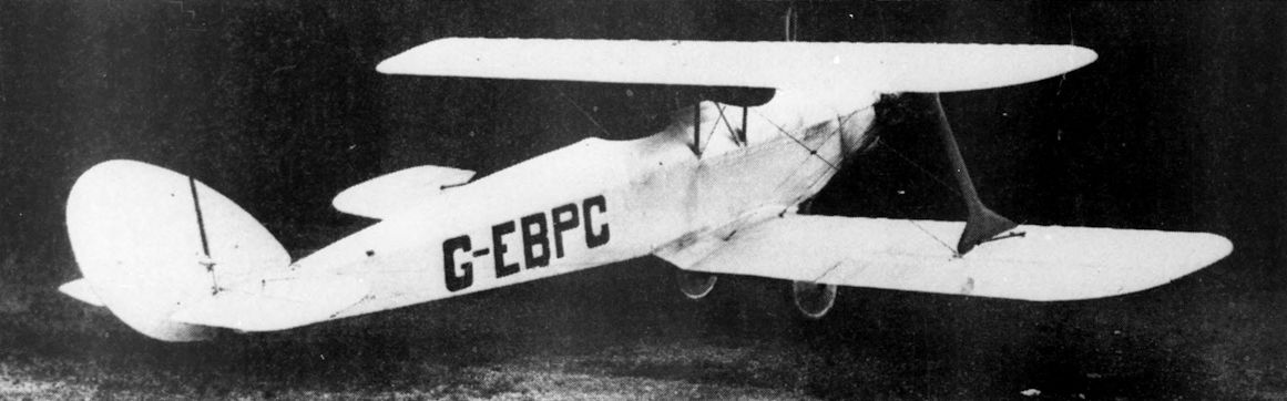
Регистрационный номер: G-EBPC [2] View of the C.L.A.4 G-EBPC, which was to have been fitted with the Pobjoy P engine. Instead, it was powered by a 36 h.p. Bristol Cherub III.
-

Aeroplane Monthly 1978-12 / R.Riding - Cranwell C.L.A.4 /British pre-war ultralights/
Регистрационный номер: G-EBPC [2] -
Aeroplane Monthly 1978-12 / R.Riding - Cranwell C.L.A.4 /British pre-war ultralights/
C.L.A.4 at the Orly meeting in September 1928, where it sustained damage to the undercarriage
-

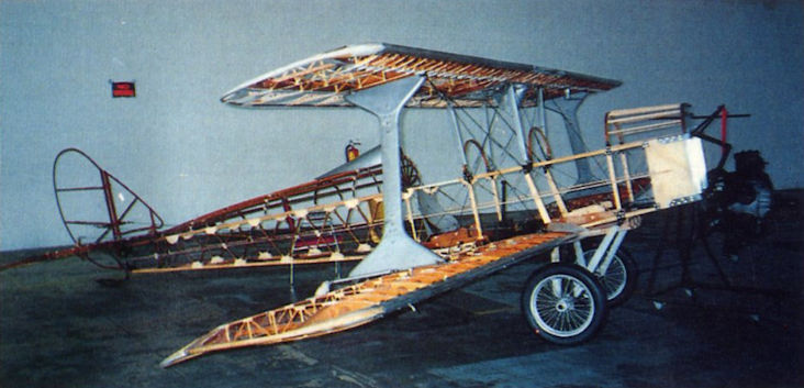
Aeroplane Monthly 1993-07 / A.Balch - Under one roof
The sole surviving Cranwell C.L.A.4, thought to incorporate parts of G-EBPC. By April this year the restored airframe was ready for recovering.
-
Flight 1926-09 / Flight
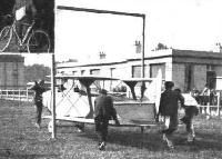
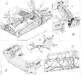
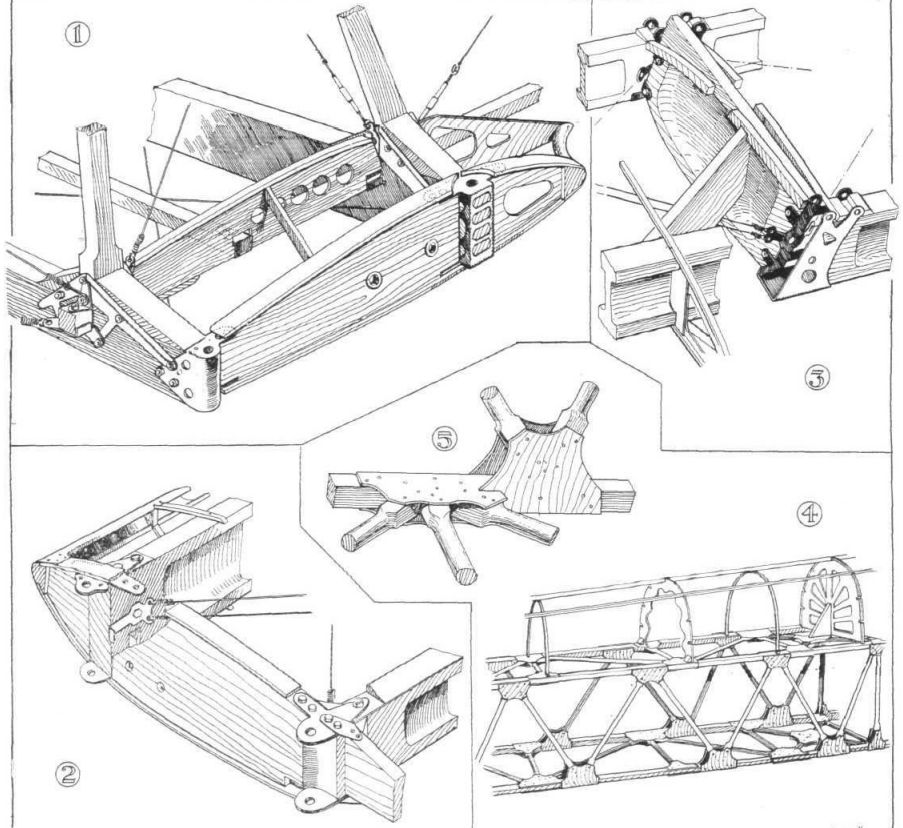
THE CRANWELL C.L.A. IV: Some constructional details: 1, The lower plane wing roots built into the fuselage. The bottom longeron is shown broken away behind the rear spar so as to show better the metal fitting, and between the spars this longeron passes just inside the inner rib. The rear undercarriage strut is attached to the front spar attachment. The hinges for folding the wings are also shown. In 2 is illustrated the inner end of the starboard lower plane, with hinge fittings, etc. The solid rib is partly broken away to show the form of the drag bracing clip. 3 illustrates the special rib and sheet steel fittings for the inter-plane I-strut on the lower plane. This strut slopes inwards, the sketch being viewed from outside the strut attachment. The spar is broken away to show the details of the special metal fitting for the attachment of the strut. The form of construction employed in the rear portion of the fuselage is illustrated in 4, while 5 shows details of this construction, the actual joint shown being on the lower longeron and viewed from inside.
-
Flight 1926-09 / Flight
Cranwell C.L.A.4 Bristol "Cherub" Engine


- Фотографии