
 Wiki
Wiki Flight, July 1925
THE CRANWELL C.L.A.3 LIGHT MONOPLANE
Bristol "Cherub" Engine
As the only new machine entered for the Royal Aero Club race meeting at Lympne, very considerable interest attaches to the little monoplane produced by the Cranwell Light Aeroplane Club for the August races. This club occupies a somewhat unique position in that it is composed of Royal Air Force officers, and, up to the present, has the distinction of having twice entered amateur-built machines for open competitions. It may be of interest to mention that the President of the Club is Squadron-Leader W. Thomas, M.C., while Flight-Lieutenant E. P. Mackay is Treasurer, and also acts in the capacity of reserve pilot. The Club's designer is Flight-Lieutenant N. Comper, who will also pilot the machine in the Lympne races. It may be mentioned that Flight-Lieutenant G. T. H. Pack is in charge of wood construction, while engine installation, cowling, etc., is in the able hands of Flying-Officer F. H. Cashmore.
It may be recollected that in last year's Lympne competition the Cranwell Light Aeroplane Club was represented by a biplane, the C.L.A.2, with Bristol "Cherub" engine, which won the reliability prize of ?300, with a total mileage of 762 1/2, and a total number of hours flying of 17 hours 53 mins. 18 secs. The biplane was a somewhat slow machine, what with the side-by-side arrangement of pilot and passenger, and this great number of hours had to be put in in order to cover the mileage in the reliability trials. The Cranwell Club thoroughly well deserved this encouragement, and everyone will be glad to learn that last year's success has induced the Club to have another try this year. The C.L.A.3 is, however, a very different kind of machine, and is expected to be one of the fastest for its power in the race. All will wish the Cranwell Club every success again this year, as theirs is a spirit much too rare in this country, where amateur designing and construction has never attained the popularity with which it is regarded abroad, particularly in Germany.
The Cranwell C.L.A.3, designed by Flight-Lieutenant Comper, A.F.R.Ae.S., is shown in the accompanying general arrangement drawings. It is a parasol monoplane of normal wood construction. Although an attempt has been made to give the machine as clean lines as possible, the cantilever principle has not been adopted for the wing construction; it probably being considered by the designer that any slight extra resistance caused by wing bracing struts would be more than made up for by the lighter structure which could be achieved when bracing was employed. The rear portion of the fuselage has flat sides and bottom, but there is a deep deck faring on top. In front, however, very great care has been taken to obtain as smooth a contour as possible, this being formed by light formers and stringers passing on the outside of the main fuselage structure, which in itself is of considerably smaller cross-sectional area. Streamline form is maintained right up to the nose, a large beaten cowl surrounding the Bristol "Cherub" engine, of which only the cylinder heads project. The monoplane parasol wing is of constant chord but has the tips rounded off. The section used is known as Eiffel No. 371. This section has given very good results in model tests, but the full size performance of it is, we believe, somewhat of an untried quantity. This section is a fairly deep one, with flat bottom camber, but having a slight rise to the leading edge. The conventional undercarriage and normal tail planes complete the aerodynamic design, which altogether may be characterised as very clean, but by no means freakish.
Constructional features
Generally speaking the Cranwell C.L.A.3, is of fairly normal construction, and naturally forms have been chosen which lend themselves to amateur construction, the whole of the work of building the machine having been carried out by members of the Club, who, it must be admitted, have made a very creditable job of it. The rear portion of the fuselage is built up as a Warren girder comprising four longerons braced by diagonal struts so as to provide perfect triangulation. This form of construction extends from the stern post to the cockpit, but from here to the engine plate wire bracing has been employed. The struts in the triangulated portion of the fuselage are of circular cross sections but terminate in square ends so as to facilitate attachment to the longerons, which attachment is in the form of three-ply gusset plates, as indicated in one of our sketches. The Bristol "Cherub" engine is mounted on overhung bearers, and, as already stated, the cowl surrounds the entire engine, with the exception of the cylinder heads. Attached to the engine plate, but extending right out to the cowling, is a fire-proof bulkhead. The petrol tank which has a capacity of 4 1/2 gals., is placed inside the deck faring in front of the pilot, in which position there is a sufficient head of petrol to give direct gravity feed.
In order to keep down the cross-sectional area the pilot's cockpit has been kept down to the smallest possible proportions, and the pilot actually sits on the floor of the cockpit. This position has necessitated a somewhat unusual arrangement of the control stick, in the fittings of which universal joints have been incorporated. The actual arrangement is shown by a sketch which should explain the details. Access to the cockpit - and perhaps more particularly exit therefrom – appears to be none too easy, although a removable panel above the top longerons somewhat facilitated matters. The machine has, however, been designed for speed work, and. consequently, certain sacrifices in other respects must be made and indeed are quite permissible in a racing machine even if objections might be made if the machine were intended for school work. From the plan view of the general arrangement drawings it will be seen that the monoplane wing does not taper. We believe that the designer would have preferred a tapered wing, but structural considerations led to the adoption of the parallel wing as being considerably easier to build. The spruce spars are both of I-Section, and the ribs are of simple lattice type. The covering is in the form of fabric while the leading edge is aluminium. The wing is carried at the centre on four steel struts rising from the top longerons and is braced on each side by two steel tube struts The method of attaching the wing-bracing struts to the wing spars is indicated by the sketches. In the case of the front spar the fitting is in the form of a strap surrounding the spar but on the rear spar a vertical bolt passes through the spar from top to bottom. The ailerons have a differential movement somewhat after the style of that used in De Havilland machines. To cover up the gap between the main rear spar and aileron leading edge, rubber strips are employed as it is expected that these will stop all air losses, at the same time allowing of free movement of the ailerons.
The tail planes are of normal design and construction and provision is made for varying the angle of incidence of the fixed tail plane. The adjustment, is, however, effected on the ground only and the tail plane is not of the trimming type.
The undercarriage is of orthodox design, with V-struts and rubber cord shock absorbers. The Cranwell C.L.A.3 has been designed with high factors of safety, as it is hoped to obtain for it an aerobatic airworthiness certificate. The main dimensions are shown on the general arrangement drawings, from which it will be seen that the machine is quite a small one, the over-all length being only 18 1/2 ft., while the wing span is but 21 ft. That very careful structural design has been incorporated will be realised when we point out that the weight of the machine empty is only 325 lbs., this figure, of course, including the weight of the "Cherub" engine. With a pilot weighing 170 lbs., and with 4 1/2 gals. of petrol and a small quantity of oil, the total loaded weight is only 530 lbs., which, with a wing area of 70 sq. ft. gives a wing loading of 7-6 lbs./sq. ft. Assuming that the Bristol "Cherub" develops 30 b.h.p. the power loading is only 17-6 lb./h.p., so that with its clean aerodynamic design the C.L.A. 3 should have a very good turn of speed. The estimated top speed is, we believe, 100 m.p.h.
- Flight, July 1925
THE CRANWELL C.L.A.3 LIGHT MONOPLANE
Фотографии

-
Aeroplane Monthly 1978-08 / R.Riding - Comper Swift /British pre-war ultralights/ (1)
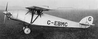
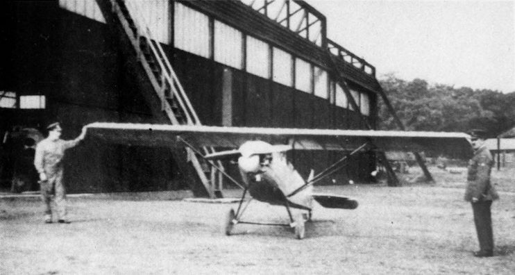
Регистрационный номер: G-EBMC [11] The C.L.A.3, from which the Swift evolved, seen at Cranwell shortly after completion in 1925. When compared with the prototype Swift, the similarities are obvious.
-
Flight 1925-07 / Flight
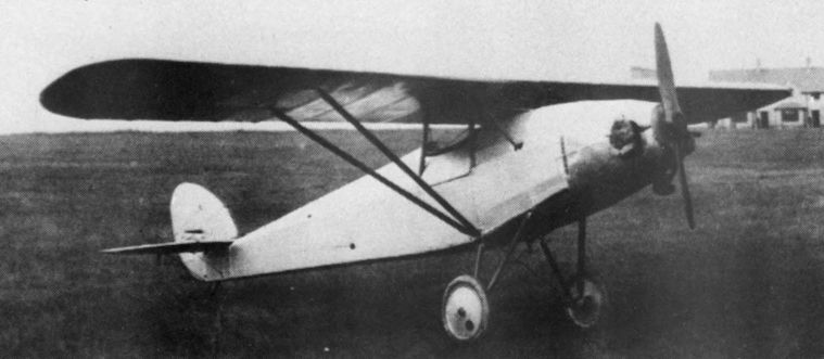
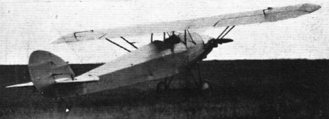
Регистрационный номер: G-EBMC [11] Cranwell C.L.A.3: Three-quarter front view. Note the careful streamlining of the nose.
-

Flight 1926-07 / Flight
Регистрационный номер: G-EBMC [11] The King's Cup: The Cranwell C.L.A.3 monoplane, 25 h.p. Bristol "Cherub" III, is already known to our readers.
-

Aeroplane Monthly 1980-08 / R.Riding - Cranwell CLA 2-3 /British pre-war ultralights/
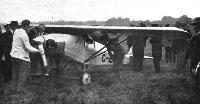
Регистрационный номер: G-EBMC [11] Two RAF officers lend scale to the newly-completed CLA3, seen at Cranwell during the summer of 1925.
-
Aeroplane Monthly 2001-09 / P.Jarrett - Inter-war One-offs /Inter-war civil/
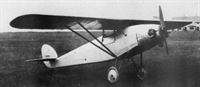
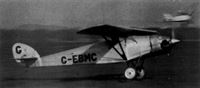
Регистрационный номер: G-EBMC [11] The CLA.2's successor was this neat little single-seat monoplane, the CLA.3, which was entered for the 1925 Lympne trials and was again powered by a 32 h.p. Cherub. The picture shows it in 1926, after a 36 h.p. Cherub driving a metal propeller with a spinner had been installed. It was scrapped in 1929.
-
Flight 1926-07 / Flight
Регистрационный номер: G-EBMC [11] THE FIFTH KING'S CUP RACE: Starting-up the Bristol "Cherub III" engine of the Cranwell C.L.A.3 monoplane, entered by Sq.-Ldr. W. Thomas (Cranwell Light Aero Club) and piloted by Flt.-Lieut. N. Comper.
-

Aeroplane Monthly 1980-08 / R.Riding - Cranwell CLA 2-3 /British pre-war ultralights/
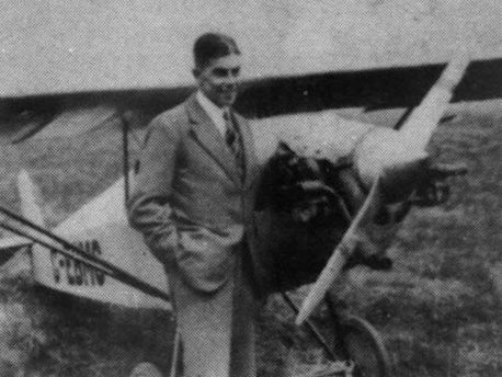
Регистрационный номер: G-EBMC [11] The designer with the CLA3, now registered G-EBMC, re-engined with a 36 h.p. Bristol Cherub and sporting a Fairey metal propeller
-
Aeroplane Monthly 1980-08 / R.Riding - Cranwell CLA 2-3 /British pre-war ultralights/
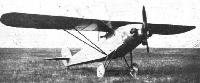
Регистрационный номер: G-EBMC [11] Another view of the CLA3 with more powerful Cherub and Fairey metal propeller. The aircraft was scrapped in 1929.
-

Flight 1925-08 / Flight
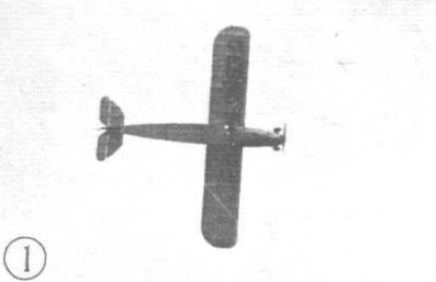
Регистрационный номер: G-EBMC [11] Comper making a vertical bank on the Cranwell C.L.A.3.
-
Aeroplane Monthly 1980-08 / R.Riding - Cranwell CLA 2-3 /British pre-war ultralights/
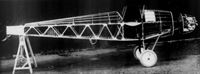
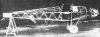
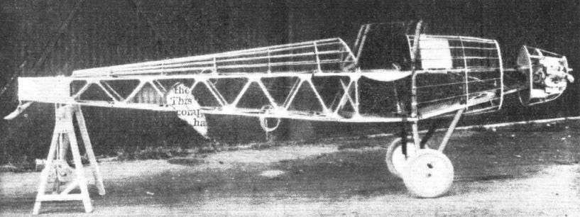
Регистрационный номер: G-EBMC [11] The CLA3 fuselage before covering. Note the position of the 4 1/2gal fuel tank just forward of the cockpit.
-
Flight 1925-07 / Flight
Регистрационный номер: G-EBMC [11] THE CRANWELL C.L.A.3 MONOPLANE: View of the fuselage, showing construction, undercarriage, engine mounting, etc.
-

Aeroplane Monthly 1980-08 / R.Riding - Cranwell CLA 2-3 /British pre-war ultralights/
The scale model of the CLA3 built for the Cranwell Light Aeroplane Club by boys of the No 4 Wing model club. It is believed to have been presented to the Science Museum.
-
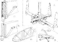
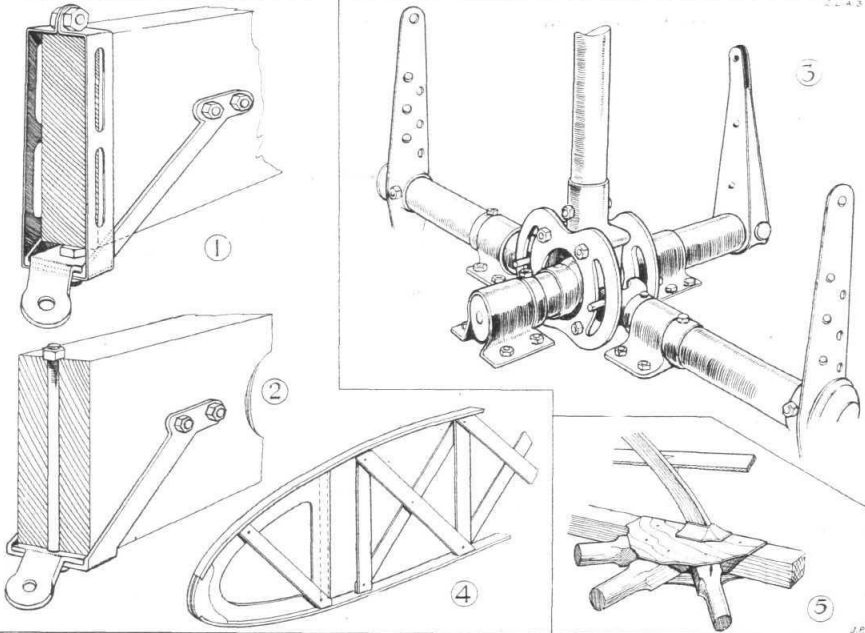
Flight 1925-07 / Flight
SOME CONSTRUCTIONAL DETAILS OF THE CRANWELL C.L.A.3 LIGHT MONOPLANE: 1. Attachment of lift strut to front wing spar. A wood block filler between fitting and bottom of spar has been omitted so as to show the bolt. 2. The rear spar strut fitting has a bolt passing vertically through the spar. 3. The controls incorporate a universal joint of somewhat unusual design, necessitated by the fact that the pilot sits on the floor of the cockpit. 4. Shows the construction of a rib, while 5 is a typical fuselage joint. The joints in the top and bottom bays are staggered in relation to those in the side bays so as to allow the three-ply gussets to clear one another.
-
Flight 1925-08 / Flight
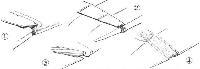
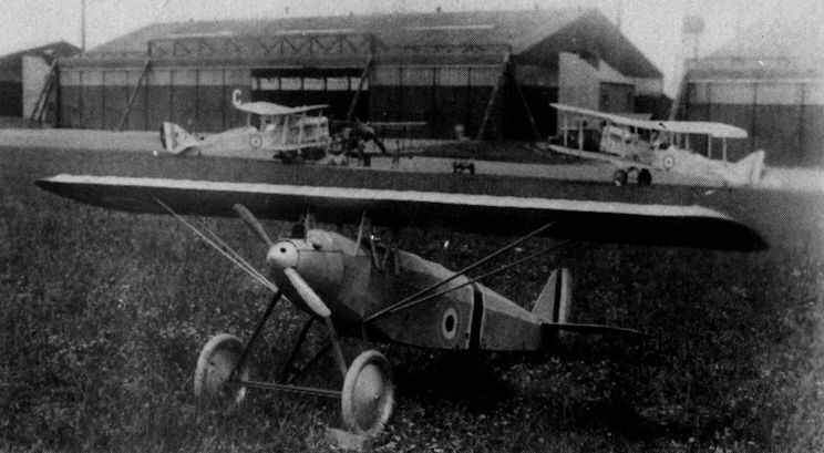
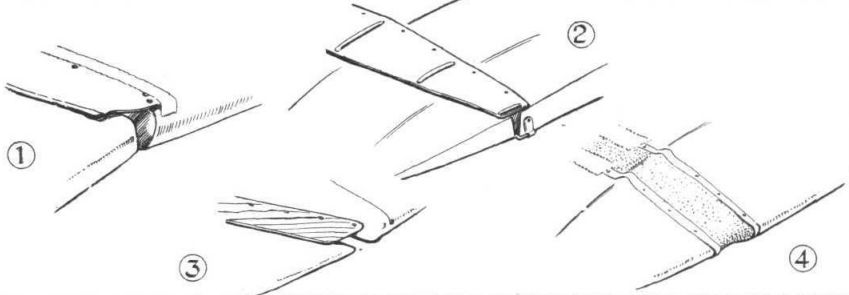
"STOP THAT LEAK": Different methods of closing the gap between rear spar and aileron in some of the Lympne machines. 1. In the Beardmore "Wee Bee" an aluminium strip is used with edges turned over for stiffening purposes. The front edge is covered by fabric strip doped on. 2. In the A.N.E.C, an aluminum strip is used, stiffened by fore-and-aft corrugations, while in 3, the Parnall "Pixie II" three-ply is employed, and in 4, the Cranwell monoplane, rubber strip. This was later removed as it tended to cause the controls to work stiffly.
Другие самолёты на фотографии: ANEC I / II - Великобритания - 1923Beardmore W.B.XXIV Wee Bee - Великобритания - 1924Parnall Pixie - Великобритания - 1923
-

Aeroplane Monthly 1980-08 / R.Riding - Cranwell CLA 2-3 /British pre-war ultralights/
Cranwell C.L.A.3 Bristol "Cherub" Engine


- Фотографии