

Flight, December 1928
THE BOULTON AND PAUL "PARTRIDGE”
All-Metal Single-Seater Fighter
THE forms of metal construction developed by Boulton & Paul, Ltd., during the last six or seven years, are probably fairly well known to readers of FLIGHT. Less known is, probably, the fact that a large number of parts have been standardised by a very ingenious system in such a manner that, to take but one example, a steel spar for aircraft, ranging in size from the single-seater fighter to a twin-engined bomber, can be produced from stock. In the "Partridge," illustrated this week, very extensive use has been made of such standardised parts, with the result that the machine could, should the occasion arise, be produced very rapidly and cheaply. That this has been achieved without sacrificing performance will be clear from the performance figures given at the end of these notes.
General Design
The "Partridge” is a tractor biplane of orthodox design as regards the general lay-out, having a top plane of larger span and chord than the lower plane. The wing section is a bi-convex one, presumably with a small travel of the centre of pressure. Great care has been taken in streamlining the fuselage, the carefully thought-out engine cowling being one of the obvious refinements.
Constructional Features
It is, however, in the constructional details that the "Partridge" is particularly interesting, and by the courtesy of Boulton & Paul, Ltd., we are able to illustrate these very fully.
The Fuselage. - The fuselage frame, which is in two parts, a forward portion which carries wings, petrol and oil tanks, pilot, guns, etc., and a rear portion extending from the cockpit to the Stern post, is of all-metal construction with exception of the covering. In the front portion of the fuselage the longerons are of high tensile solid-drawn steel tube of stock sizes. The top longerons in the bay occupied by the cockpit are of very large diameter tube, and form the sole support of the Vickers guns. By their great size and strength they also give exceptional stiffness to this bay, and afford good protection in the event of a crash. In the rear portion of the fuselage, the longerons are of the well-known "closed-joint" type of tube, manufactured from steel strip, which this firm has developed during recent years, and which is used so extensively in the rigid airship R.101. Stock sizes are used in the "Partridge."
The fuselage struts are of various types according to the location in the fuselage and the diameter-thickness ratio required. Solid drawn high-tensile steel tubes, Boulton & Paul closed-joint tubes in steel and Duralumin, and solid drawn Duralumin tubes are all employed. The sockets and end fittings are all of standard Boulton & Paul stock parts, and make use of the tubular magnesium pads which this firm uses so extensively. A sketch shows the standard arrangement found in the rear portion of the fuselage. In the front portion the joints are slightly different, particularly those which carry the front and rear wing spars. These also are illustrated by sketches, from which it will be seen that use is made of a light alloy sleeve and two high-tension steel discs. Bracing is by tie rods throughout with the exception of the side bays of the cockpit, which are braced by diagonal tubes.
Great attention has been paid to the fairing of the fuselage in order to obtain as far as possible an unbroken streamline. With the exception of the gun tunnels, which are of sheet steel, the construction of the fairing is carried out in wood and fabric. Doors of adequate size are provided for access to wireless crate, guns, ammunition boxes, oxygen cylinders, petrol filter, instruments, etc.
Wings. - As already mentioned, the wings of the "Partridge" are of biplane formation, and in the second machine ailerons of the "Frise" type will be fitted to both top and bottom planes, as indicated in the general arrangement drawings. The wing tips are kept square in order to retain simplicity of construction. It is thought that the square type of wing tip used is as efficient aerodynamically as would be a rounded tip.
A somewhat unusual feature in the wing arrangement of the "Partridge" is provided by the absence of any top centre-section. The two halves of the top plane meet on the centre line, and the top spars are joined together by simple fish plates. One result of this arrangement is a certain saving in the number of spares required. The bottom wing halves are joined to the fuselage frame by pin joints, details being illustrated in the sketch, Fig. 4, on this page. The wing bracing is in the form of a single bay each side, with the usual lift, anti-lift and incidence bracing of streamline wire.
In the construction of the wings standard stock sections are employed throughout, the main spars being of high tensile steel and the ribs of Duralumin. The sketches on p. 1033 show most of the typical details of the wing construction, such as main spars, ribs, leading and trailing edges, etc. The spars are of the standard Boulton and Paul type, with corrugated flanges and webs, with tubular and plate stiffeners. In nearly all types of built-up box spars of metal, the problem is not so much to produce a strong and cheap spar but to turn out one to which ribs and inter-plane strut fittings can be easily and neatly attached. The way in which the ribs are attached to the spars in the "Partridge" is illustrated on p. 1033. Channel section pressings have projections which enter the rib flanges and are riveted to them, the pressings being slotted to locate the rib on the spar, and held in place by large tubular rivets which pass through the standard tubular stiffeners in the spar webs. The methods of attaching leading and trailing edges will be clear from the sketches, but it might be pointed out that in the case of the trailing edge use is made of small die castings riveted to the rib flanges. The ribs, it should be mentioned, are all of Duralumin, and are generally of the type shown, although certain special ribs are of slightly different construction.
The inter-plane struts are made of Boulton and Paul standardised sections in Duralumin. They consist of a main member made in two parts: a front portion of U-section and closed at the back by a transverse wall, which forms the load-carrying part of the strut and also the nose of the streamline section. To this main strut structure is attached a tail fairing of wood, which slides into the flanges provided at the rear of the main front member. The attachment to main spar joints is by a "T”-shaped fitting and one bolt, as shown in Fig. 2, on p. 1031.
The type of joint used for connecting inter-plane struts, drag struts, wire bracing, etc., to main spars is shown in Fig. 1, on p. 1031. The joint consists of high-tensile steel channel plates riveted to the spar webs on each side, and of detachable high-tension steel side plates. With the exception of the side plates, all parts of the spar joints are made with standardised tools.
The tail surfaces are, generally speaking, of similar construction to the wings.
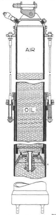
Undercarriage. - This is of standard type for single-seater fighters, i.e., a plain two-wheeled structure with cross axle and oleo-pneumatic front legs for absorbing the shock, the rear legs of the vee being radius rods. A diagrammatic sectional view of an undercarriage leg illustrates the general principle.
The tail skid is of the tracking type, and has a shock absorbing leg making use of rubber blocks in compression. The skid is steerable by the rudder bar through cables and a spring box to absorb ground shocks.
Engine Mounting and Cowling. - The engine mounting consists of a high-tensile steel ring plate connected to the longerons of the front frame of the fuselage by four solid drawn high tensile steel tubes, braced in the side bays by similar tubes and in the top plan bay by tie rods. The engine cowling, which blends into the streamline body shape, consists of a forward heavy ring or dummy exhaust ring, and a ring behind the cylinders connected by stiffened plates between each pair of cylinders. The cowling has been designed with a view to its easy and rapid removal, and is very robust. The dummy exhaust ring can be replaced by a real exhaust ring without modification to the remainder of the cowling.
Petrol and Oil Systems. - The petrol tank is situated in the front frame of the fuselage, between engine and pilot. It consists of an outer shell with its top surface forming a removable lid, an internal tubular structure partly braced by tie rods and partly by the inner service tank which is built into the main tank. The inner tank serves the dual purpose of service tank and baffle, and is filled automatically through a re-entrant filler from the main tank. Inner and outer tanks are connected to a three-way cock so constructed that only one tank can feed the engine at one time. The internal structure, in addition to stiffening the tank, forms the greater part of the tank bearer and also braces the fuselage frame bay which contains it without transmitting the stresses to the tank shell. The connection between the tank shell and the internal structure ends consists of plugs screwed into the tube ends from outside, and using special cork washers.
The oil tank is situated on the starboard side of the fuselage, and incorporates an oil cooler in its outer surface, which conforms to the shape of the body Oil is fed into the cooler through a valve so arranged that should the oil pressure rise above a certain amount, the oil is by-passed direct into the tank, the cooling being thus automatically controlled.
Cockpit Arrangements
The pilot's seat is of the "pan" type to accommodate the seat type of parachute. It is adjustably mounted (see sketch) by means of a lever working in a notched quadrant, so that the pilot can raise and lower the seat while in flight.
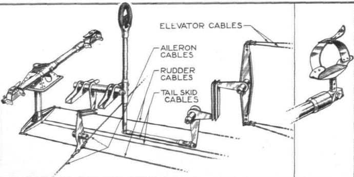
The controls are of normal type, and include a tail-trimming gear with an indicator of angles placed on the instrument board. A perspective diagrammatic sketch illustrates the general scheme of the controls, and should be self-explanatory.
The equipment includes two Vickers guns with ammunition, wireless, parachute, oxygen apparatus, etc.
Main Characteristics and Performance
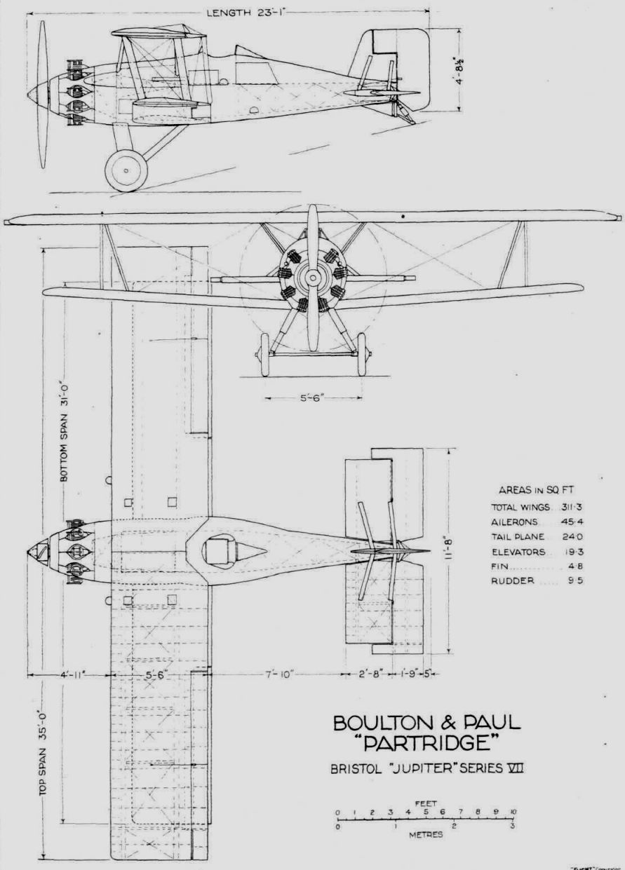
The chief dimensions of the Boulton and Paul "Partridge" are given on the general arrangement drawings. With Bristol "Jupiter Series VII" the machine has a total all-up weight of 3,097 lbs. (1,408 kg.) made up as follows :-
Lbs. Kg.
Power unit (including fuel and oil) 1,500 (682)
Wings 424 (193)
Fuselage 342 (155)
Tail unit 79 (36)
Undercarriage and skid 156-5 (71)
Controls 45-5 (20-7)
Military load 550 (250)
For a total loaded weight of 3,160 lbs. (1,436 kg.) the "Partridge" has a top speed at 20,000 ft. (6,100 m.) of 164 m.p.h. (264 km./h.) and a service ceiling of 28,950 ft. (8,825 m). The landing speed is 61 m.p.h. (98 km./h.).
- Flight, December 1928
THE BOULTON AND PAUL "PARTRIDGE”
Фотографии

-

Flight 1928-06 / Flight
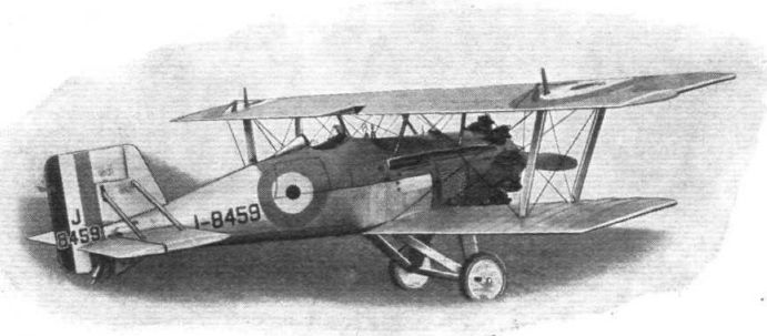
Регистрационный номер: J8459 [4] BOULTON & PAUL "PARTRIDGE": Single-Seater Fighter, with Bristol "Jupiter" Engine.
-

Flight 1928-12 / Flight
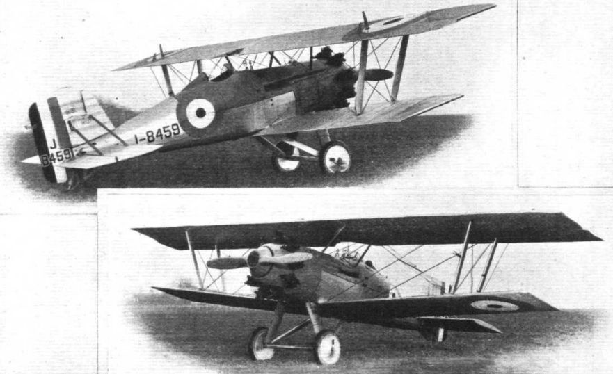
Регистрационный номер: J8459 [4] THE BOULTON AND PAUL "PARTRIDGE": These two views show the first machine. In the second, ailerons will be fitted to both planes. The engine is a Bristol "Jupiter" Series VII supercharged.
-

Flight 1929-01 / Flight Advertisements
Регистрационный номер: J8459 [4] The Boulton & Paul "Partridge" single-seater fighter of all-metal construction.
-

Flight 1929-01 / Flight Advertisements
Регистрационный номер: J8459 [4] Boulton & Paul "Partridge" Single-Seater Fighter, and "Sidestrand" Day Bombers of all-metal construction, fabric covered.
Другие самолёты на фотографии: Boulton Paul Sidestrand / P.29 - Великобритания - 1926
-

Flight 1928-12 / Flight
The Boulton and Paul "Partridge": Sectional view of oleo-pneumatic undercarriage leg.
-

Flight 1928-12 / Flight
The Boulton and Paul "Partridge": Perspective diagrammatic view of the controls. Inset, the adjustable pedal.
-

Flight 1928-12 / Flight
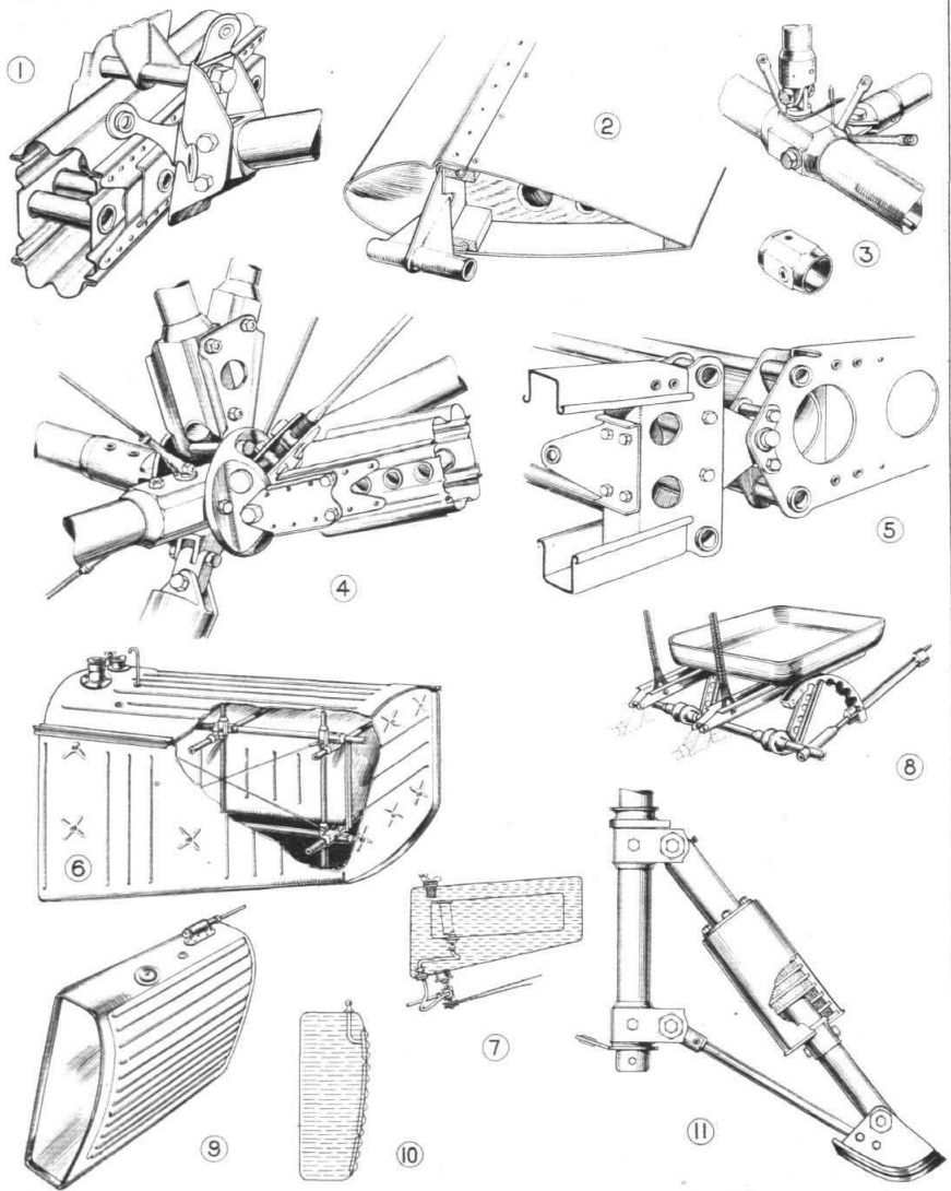
THE BOULTON AND PAUL "PARTRIDGE": Some constructional details. (1) Main wing spar joint. (2) Inter-plane strut with end attachment. (3) A typical fuselage frame joint. (4) The wing spar attachment joint in front portion of fuselage frame. (4) Outer hinge of elevator. (6) and (7) Sectioned view and section of petrol tank. (8) The arrangement of pilot's adjustable seat. (9) The oil tank. (10) Vertical section of oil tank showing cooler. (11) The tail skid.
-

Flight 1928-12 / Flight
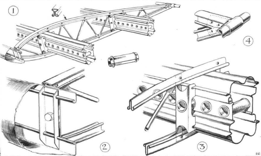
THE BOULTON AND PAUL "PARTRIDGE": Some constructional details of the wings. (1) General view showing main spars and a rib. (2) Attachment of metal leading edge to rib. (3) Attachment of rib to main spar. (4) Attachment of tubular trailing edge to rib.
-

Air Enthusiast 2003-11 / A.Brew - Proud heritage
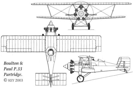
Boulton & Paul P.33 Partridge.
-

Flight 1928-12 / Flight
Boulton & Paul "Partridge" Bristol "Jupiter" Series VII

- Фотографии