

Описание
Страна : Великобритания
Год : 1926
Средний бомбардировщик с экипажем из трех - четырех человек
Варианты
- Boulton Paul - Sidestrand / P.29 - 1926 - Великобритания
- Boulton Paul - Overstrand / P.75 - 1933 - Великобритания
Boulton & Paul Р.29 Sidestrand
Опыт, полученный в ходе разработки двухмоторных бомбардировщиков Р.5, Р.15 и Р.25, фирма "Boulton & Paul" воплотила в самолете Р.29 Sidestrand, спроектированном согласно спецификации 9/24 к среднему дневному бомбардировщику с экипажем из трех - четырех человек. Первый из двух прототипов Sidestrand Mk I поднялся в воздух в 1926 году. Поскольку машина являлась развитием ранее построенных и испытанных самолетов, фирма сразу получила заказ на 18 серийных бомбардировщиков.
Серийные машины начали поступать в 101-ю эскадрилью британских ВВС в 1928 году. Первую партию из шести самолетов собрали в варианте Sidestrand Mk II с моторами Bristol Jupiter VI мощностью по 425 л. с. с непосредственным приводом на винты, как на первых двух прототипах. За первой серией последовала вторая из девяти машин с моторами Bristol Jupiter VIIIF, оснащенными понижающими редукторами. Эти самолеты обозначались Sidestrand Mk III. Три последних выпущенных бомбардировщика изготовили в варианте Sidestrand Mk II.
Sidestrand поступил на вооружение только в 101-ю эскадрилью. Три экземпляра Sidestrand Mk III доработали в вариант Sidestrand Mk V(Overstrand). В декабре 1934 года начался процесс замены самолетов Sidestrand более совершенными бомбардировщиками.
ТАКТИКО-ТЕХНИЧЕСКИЕ ХАРАКТЕРИСТИКИ
Boulton & Paul Р.29 Sidestrand Mk III
Тип: средний бомбардировщик с экипажем из трех - четырех человек
Силовая установка: два звездообразных мотора Bristol Jupiter VIIIF мощностью no 460 л. с.
Летные характеристики: макс, скорость на высоте 3050 м - 225 км/ч; время набора высоты 4570 м - 19 мин; практический потолок 7300 м; дальность 800 км
Масса: пустого 2726 кг; максимальная взлетная 4627 кг
Размеры: размах крыла 21,92 м; длина 12,40 м (увеличена до 14,02 м после установки сервокомпенсатора руля направления); высота 4,52 м; площадь крыльев 91,04 м2
Вооружение: по одному 7,7-мм пулемету Lewis на носовой, над- и подфюзеляжной турелях, до 476 кг бомб на внутренней подвеске в фюзеляже и снаружи под центропланом нижнего крыла
Описание:
- Boulton & Paul Р.29 Sidestrand
- Flight, September 1927
THE BOULTON & PAUL "SIDESTRAND” - Flight, March 1928
THE BOULTON & PAUL "SIDESTRAND I" - Flight, July 1928
THE BOULTON & PAUL "SIDESTRAND” - Flight, June 1929
BRITISH AIRCRAFT AT OLYMPIA - Flight, October 1930
AN IMPROVED "SIDESTRAND” - Flight, May 1931
THE LATEST "SIDESTRAND"
Фотографии

-

Aeroplane Monthly 1994-11 / P.Jarrett - Sidestrand and Overstrand /By day and by night/ (1)
Регистрационный номер: J7938 [12] J7938, the first Sidestrand prototype, at Martlesham Heath in its initial form, with inset horn-balanced ailerons and the angular fin and rudder inherited from the Bugle.
-
Aeroplane Monthly 1986-10 / A.Lumsden, T.Heffernan - Probe Probare (29)
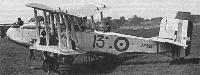
Регистрационный номер: J7938 [12] The first prototype Sidestrand seen at the 1927 RAF Pageant at Hendon, numbered 13 in the New Types Park.
-

Flight 1927-06 / Flight
Boulton and Paul "Sidestrand" (Two Bristol "Jupiters"). For a day bomber the "Sidestrand" is a somewhat unusual machine, the twin-engine arrangement having certain very considerable advantages connected with view, field of fire, etc. Generally the resistance of the wing engines is a serious item, but by careful study of the flow of the streamlines it has been possible, in the "Sidestrand" to reduce interference effects to a minimum, with the result that the performance is something rather out of the ordinary. The careful planning of the lines of the fuselage should be noted. Needless to say, the machine is of all-steel construction.
-

Flight 1928-03 / Flight
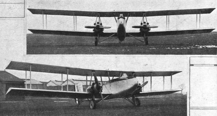
THE BOULTON & PAUL "SIDESTRAND": Front and three-quarter front views. Large span, and "clean" fuselage and engine nacelles are characteristic features.
-

Air Enthusiast 2003-11 / A.Brew - Proud heritage
Регистрационный номер: J7938 [12] The prototype P.29 Sidestrand, J7938, in August 1929.
-

Flight 1927-09 / Flight
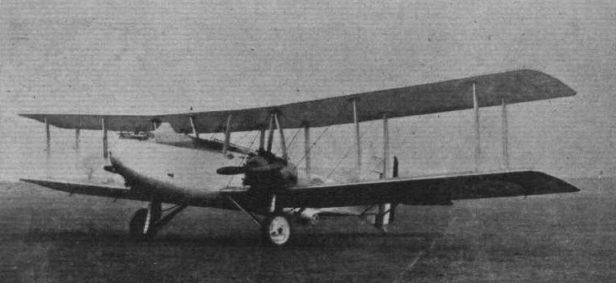
Регистрационный номер: J7938 [12] THE BOULTON & PAUL "SIDESTRAND": Designed for day bombing and similar duties, this all-metal machine is fitted with two Bristol "Jupiter" engines. The clean lines of the fuselage and engine nacelles should be noted. The gun position in the floor of the fuselage allows of firing under the tail.
-

Flight 1928-07 / Flight
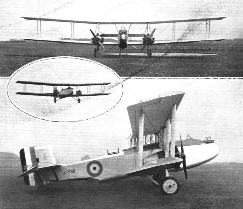
Регистрационный номер: J7938 [12] THE BOULTON & PAUL "SIDESTRAND": Side view. Note the three gun positions, and more particularly that for the aft gunner firing under the tail.
The prototype Sidestrand, J7938, made its maiden flight in 1926. It became the RAF’s first twin-engined day bomber since the D.H.10 and was the Service’s first medium bomber. -

Flight 1928-03 / Flight
Регистрационный номер: J7938 [12] THE BOULTON & PAUL "SIDESTRAND": Three-quarter rear view. The careful streamlining of the engine nacelle can be seen in this photograph.
-

Aeroplane Monthly 1986-10 / A.Lumsden, T.Heffernan - Probe Probare (29)
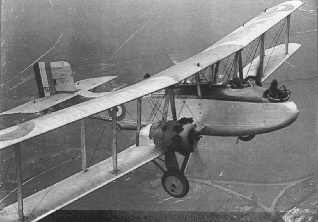
Регистрационный номер: J7938 [12] THE BOULTON & PAUL "SIDESTRAND": An aerial view from above, taken from a de Havilland "Moth."
-

Aeroplane Monthly 1986-10 / A.Lumsden, T.Heffernan - Probe Probare (29)
Регистрационный номер: J7938 [12] Another view of the prototype Sidestrand. In addition to nose and dorsal, there was a third firing beneath the tail.
-

Aeroplane Monthly 1994-11 / P.Jarrett - Sidestrand and Overstrand /By day and by night/ (1)
Регистрационный номер: J7938 [12] REPRESENTATIVE TYPES OF BRITISH AIRCRAFT: 4. The Boulton & Paul "Sidestrand II-Jupiter" three-seater bomber.
The first prototype P.29 Sidestrand I, J7938, after the fitting of Frise ailerons but with its original fin and rudder. -

Flight 1928-06 / Flight
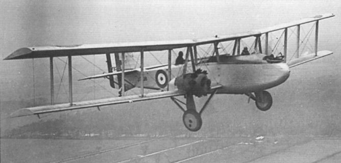
Регистрационный номер: J7938 [12] BOULTON & PAUL "SIDESTRAND": Medium Range Bomber, with two Bristol "Jupiter" Engines.
-

Aeroplane Monthly 1994-12 / P.Jarrett - Sidestrand and Overstrand /By day and by night/ (2)
Регистрационный номер: J7938 [12] Comparison of the first prototype Sidestrand, J7938, with the Overstrand emphasises the beefier and more pugnacious appearance of the latter. While J7938 weighed 8,850lb loaded, a loaded Overstrand tipped the scales at 12,000lb. J7938 is seen here after Frise ailerons had been fitted, but with the original square fin and rudder without a servo-rudder.
-

Flight 1928-03 / Flight
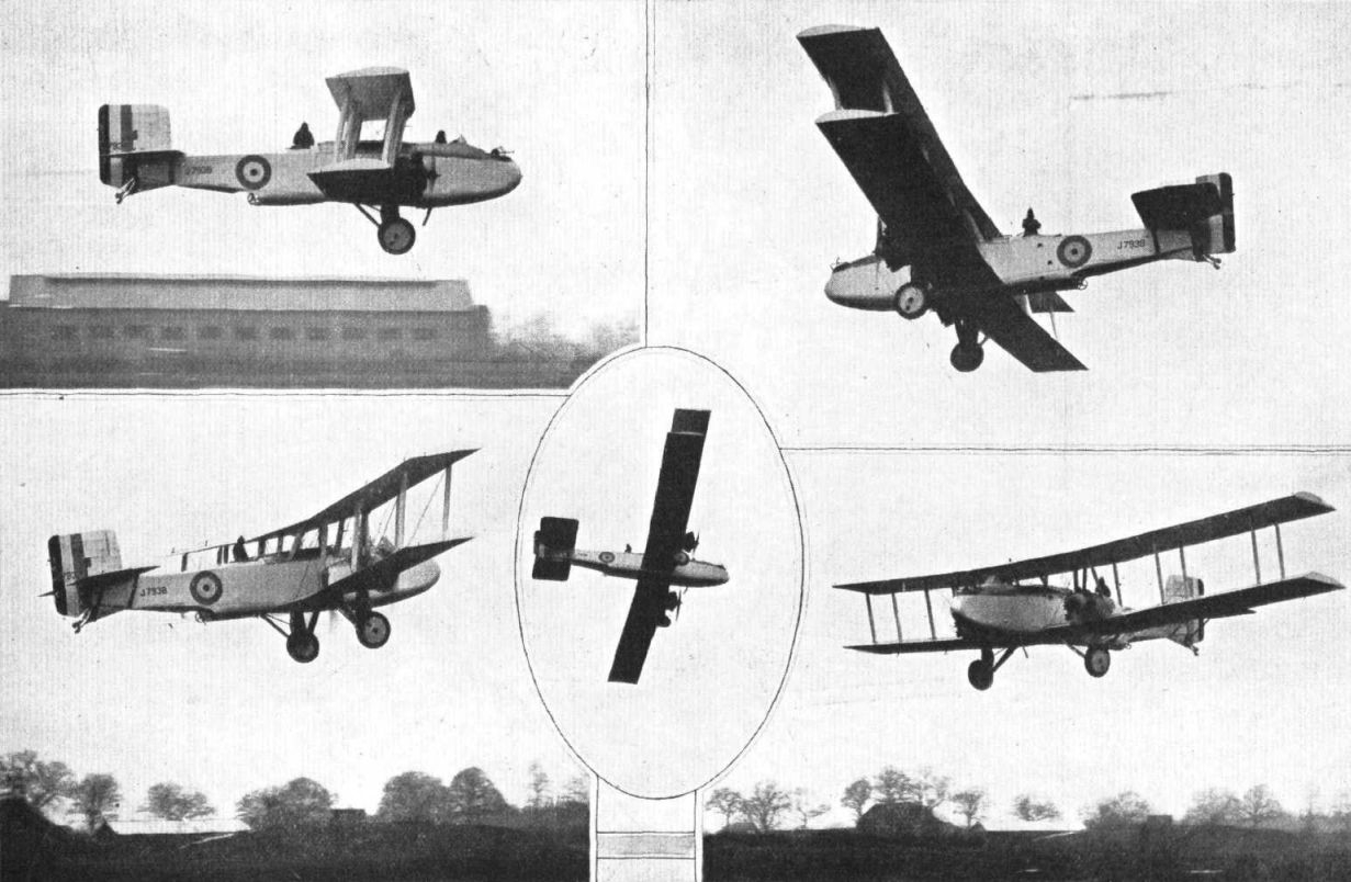
Регистрационный номер: J7938 [12] SPAN2/W: Five photographs of the Boulton & Paul "Sidestrand" in various attitudes, which show the large span and "clean" lines of the machine.
-

Aeroplane Monthly 1994-11 / P.Jarrett - Sidestrand and Overstrand /By day and by night/ (1)
Регистрационный номер: J7939 Sidestrand second prototype J7939 at the A&AEE, with Pegasus engines, four-bladed propellers and a nose window for a seated bomb-aimer.
-

Flight 1929-07 / Flight
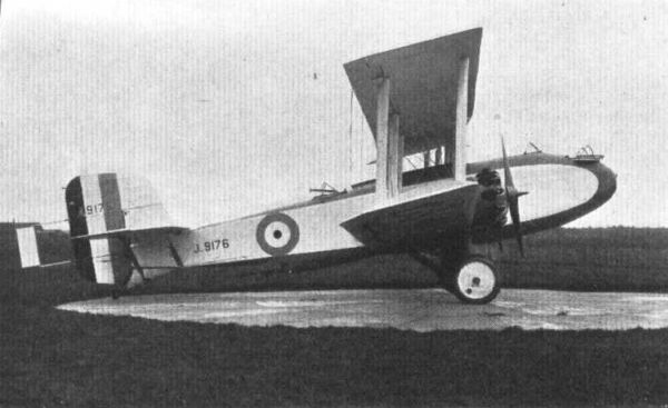
Регистрационный номер: J9176 [2] BOULTON & PAUL "SIDESTRAND" (2 Bristol "Jupiters")
-

Flight 1931-04 / Flight
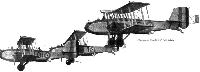
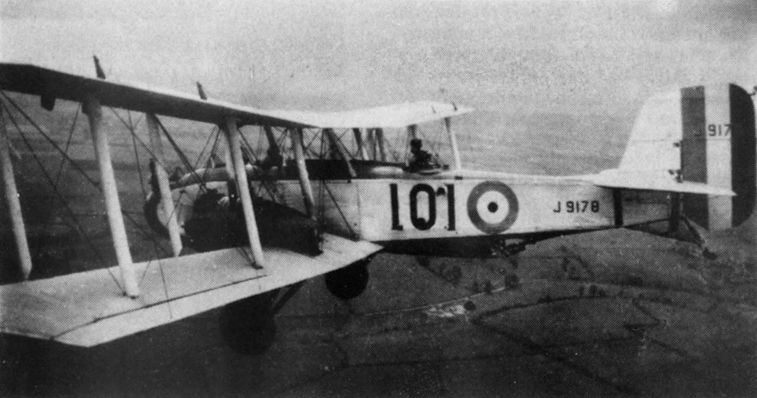
Регистрационный номер: J9176 [2], J9178 [3], J9189 Four "Sidestrands" of No. 101 (Bomber) Squadron flying in echelon on the left. This view shows the position of the underneath gun very well, and also the absence of resistance from bomb racks, which are hidden within the contour of the fuselage.
-

Aeroplane Monthly 1978-08 / Personal album
Регистрационный номер: J9178 [3] Boulton Paul Sidestrand J9173 of "A" Flight 101 Squadron, based at RAF Andover in 1930. The pilot was Sgt Middleton, and the rear gunner is our contributor, “ACI Johnson, J.” The only unit to be equipped with Sidestrands, 101 was for many years the RAF’s only twin-engined day bomber squadron.
-

Aeroplane Monthly 1994-12 / P.Jarrett - Sidestrand and Overstrand /By day and by night/ (2)
Регистрационный номер: J9181 [3] An underside view of Sidestrand II J9181 which shows the Frise ailerons and the extended slats on the leading edge of the upper wingtips. This aircraft became “J” of 101 Sqn, and was later converted to Mk III standard.
-

Aeroplane Monthly 1994-11 / P.Jarrett - Sidestrand and Overstrand /By day and by night/ (1)
Регистрационный номер: J9181 [3] P.29a Sidestrand Mk II J9181, the last aircraft of the first production batch.
Boulton and Paul Sidestrand III (Jupiter VIII engines). -

Aviation Historian 11 / R.Pegram - Folland's Forgotten Monoplanes (3)
Регистрационный номер: J9181 [3] The Boulton & Paul Sidestrand was the first RAF aircraft to be designated as a medium bomber, entering service with No 101 Sqn (the only unit to operate the type) in March 1929 and remaining on strength until 1936. Folland and Mayo’s bomber design was intended as a replacement for the ageing, but surprisingly agile, biplane bomber.
-
Aeroplane Monthly 1986-10 / A.Lumsden, T.Heffernan - Probe Probare (29)
Регистрационный номер: J9186 [3] Sidestrand III J9186 after modification of its undercarriage and addition of a tailwheel.
-

Aeroplane Monthly 1994-11 / P.Jarrett - Sidestrand and Overstrand /By day and by night/ (1)
Регистрационный номер: J9186 [3] Sidestrand II J9186 under test with lever-suspension main undercarriage and a tailwheel.
-

-

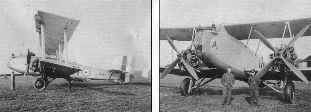
Aeroplane Monthly 1991-10 / Personal album. Military
Регистрационный номер: J9768 [2] Two photographs of the Boulton and Paul Sidestrand medium day-bomber J9768. This Mk III aircraft was delivered to the RAF in mid-1930 and was assigned to 101 Sqn in July that year. After reconditioning by the makers it was returned to the squadron but crashed while taking off from RAF Andover during an endurance test on March 5, 1933. Following repairs, it was then hit by Bristol Bulldog K1640 of 3 Sqn during combat practice at RAF Upavon on June 1, 1933. After further reconditioning by Boulton and Paul it flew once again. The only squadron to operate the Sidestrand was No 101. Sidestrands were originally based at RAF Bircham Newton, but were later transferred to Andover.
-

Flight 1931-04 / Flight
Регистрационный номер: J9768 [2] Р.29 Sidestrand представлял собой типичный равнокрылый биплан.
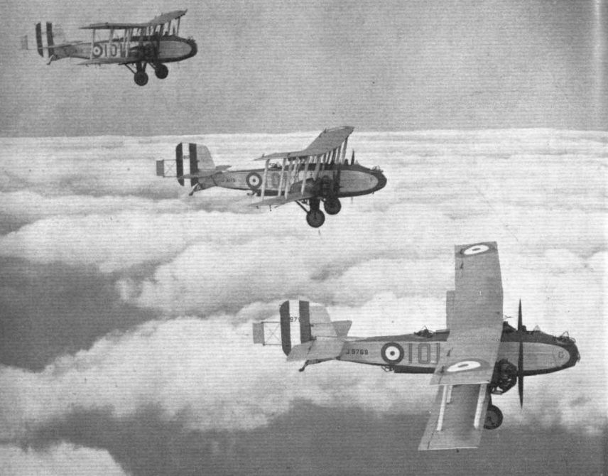
Three "Sidestrands" of No. 101 (Bomber) Squadron flying in echelon. -
Aeroplane Monthly 1986-10 / A.Lumsden, T.Heffernan - Probe Probare (29)
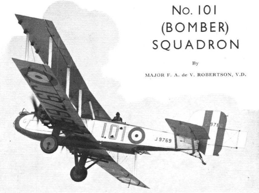
Регистрационный номер: J9769 [2] No 101 Squadron was the only RAF unit to equip with the Sidestrand. Seen here is J9769 of that unit.
-

Flight 1931-04 / Flight
Регистрационный номер: J9769 [2] -

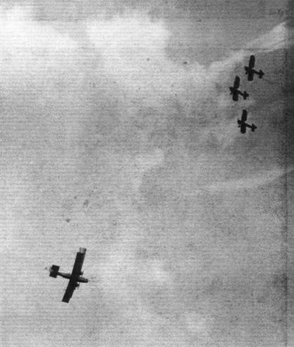
Flight 1930-08 / Flight
A Flight of No. 23 Fighter Squadron catches the Sidestrands of No. 101 B.S. at Andover.
Другие самолёты на фотографии: Gloster Gamecock - Великобритания - 1925
-

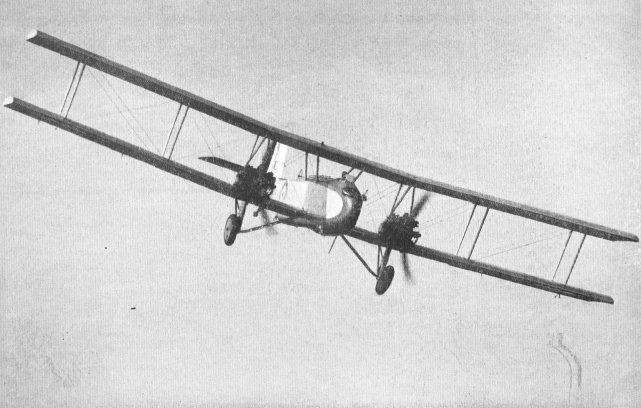
Flight 1929-07 / Flight
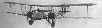
BOULTON AND PAUL "SIDESTRAND": High-performance bomber, with two Bristol "Jupiters."
-
Flight 1933-07 / Flight Advertisements
Boulton & Paul Sidestrands as supplied to the Royal Air Force
-

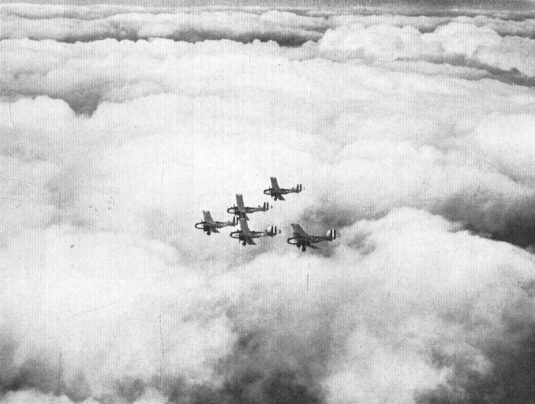
Flight 1931-04 / Flight
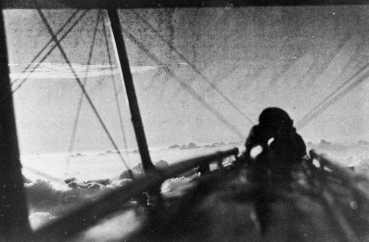
Five "Sidestrands" of No. 101 (Bomber) Squadron flying in formation above the clouds. Owing to the angle at which the photograph was taken, the aircraft appear to be closer than they really arc. Ample room is left between them so that there shall be no risk of a collision.
-

Flight 1932-07 / Flight
AIR COMBAT: "Sidestrand" v. "Bulldogs."
Другие самолёты на фотографии: Bristol Bulldog - Великобритания - 1927
-

Flight 1933-09 / Flight
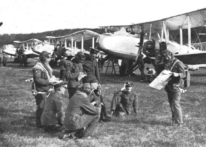
AT LEUCHARS: The Boulton & Paul "Sidestrands" (two "Jupiters") of No. 101 (Bomber) Squadron in readiness for a raid.
-

-

Flight 1931-04 / Flight
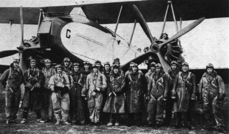
The group shows the officers and airmen of "B" Flight, No. 101 (Bomber) Squadron.
-

Flight 1931-04 / Flight
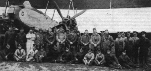
The group shows the officers and airmen of "A" Flight, No. 101 (Bomber) Squadron.
-

Aeroplane Monthly 1994-12 / P.Jarrett - Sidestrand and Overstrand /By day and by night/ (2)
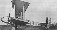
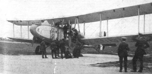
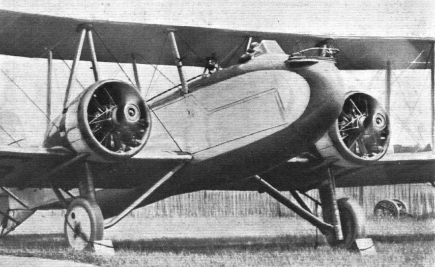
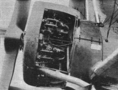
The Boulton and Paul "Sidestrand" is exhibited stripped on one side and covered on the other. Both engine mountings and fuselage nose piece are hinged.
A semi-naked Sidestrand II reveals its structural details to the press and public at the Aero Show at Olympia, London, in July 1929. Especially well shown are the hinged engine mountings, which gave easy access to auxiliaries without the need to disconnect any fuel, oil or control connections, and the hinged nose section which allowed the nose-gunner’s position to be swung to port to make interior equipment accessible. -

Aeroplane Monthly 1994-11 / P.Jarrett - Sidestrand and Overstrand /By day and by night/ (1)
Регистрационный номер: J9186 [3] Sidestrand II J9186 at Mousehold in late 1930, with Bristol Jupiter XF supercharged engines and combined Townend rings and exhaust collectors.
Sidestrand III J9186 before undercarriage modification, and fitted with circular Townend rings. -

Flight 1930-10 / Flight
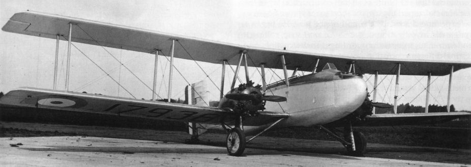
THE LATEST "SIDESTRAND": The engines are Bristol "Jupiter" X F's. Note the Townend rings.
-

Air Enthusiast 2003-11 / A.Brew - Proud heritage
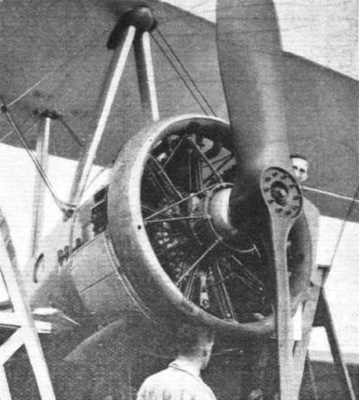
A Townend ring being removed from a Sidestrand.
-

Flight 1930-12 / Flight
The Boulton and Paul Townend exhaust ring is here shown around a Jupiter engine; some cowling panels behind the ring are removed, showing access to engine.
-

Flight 1930-11 / Flight
The Boulton and Paul Townend Ring is combined with the exhaust collector. Some of the panels removed to show accessibility.
-

Aeroplane Monthly 1974-12 / C.Sims - Camera in cloudscape
A Boulton & Paul Sidestrand of 101 Squadron returns from operations in 1934.
-

Aeroplane Monthly 1994-11 / P.Jarrett - Sidestrand and Overstrand /By day and by night/ (1)
Регистрационный номер: J9178 [3] KEITH WOODCOCK’S painting depicts Sidestrand Mk III J9178 “A” of A Flight, 101 Sqn RAF, in 1931.
-

Flight 1929-01 / Flight Advertisements
Boulton & Paul "Partridge" Single-Seater Fighter, and "Sidestrand" Day Bombers of all-metal construction, fabric covered.
Другие самолёты на фотографии: Boulton Paul Partridge / P.33 - Великобритания - 1928
-

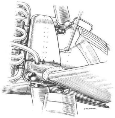
Flight 1928-03 / Flight
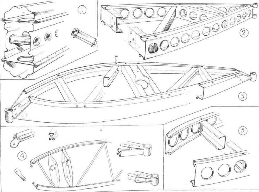
THE BOULTON & PAUL "SIDESTRAND I": 1, The engine mountings for the Bristol "Jupiter" are designed to avoid getting torque reaction loads as bending moments on the wing spars. A typical fuselage joint is illustrated in 3, and dissected in 4. Note particularly the locked-joint tube longeron and the magnesium alloy pad with flat faces for the fittings. A slightly different fuselage joint is shown in 2.
-

Flight 1928-03 / Flight
THE BOULTON & PAUL "SIDESTRAND I": Some constructional details of the wings. 1 is a spar section, with inset showing the distance-tube bracing the web walls together. A standard wing wib is shown in 4. The attachment to the spars is by means of the notched plates shown, the notches fitting over the spar flanges along the line of rivets. A somewhat stronger form of rib, used at points where concentrated loads occur, is illustrated in 2, while 3 shows a rudder rib. Further details are illustrated in 5.
-

Flight 1929-08 / Flight
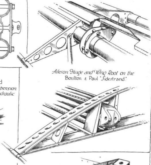
Aileron Hinge and Wing Root on the Boulton & Paul "Sidestrand"
-

Flight 1929-07 / Flight
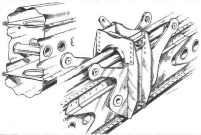
Main wing spars and interplane strut attachment thereto on the "Sidestrand."
-

Flight 1929-07 / Flight
Main structure of metal interplane strut as used on the "Sidestrand." A fairing completes the strut.
-

Flight 1929-07 / Flight
New cowling and air intake arrangement on "Sidestrand." Note the oil cooler on top of the fairing.
-

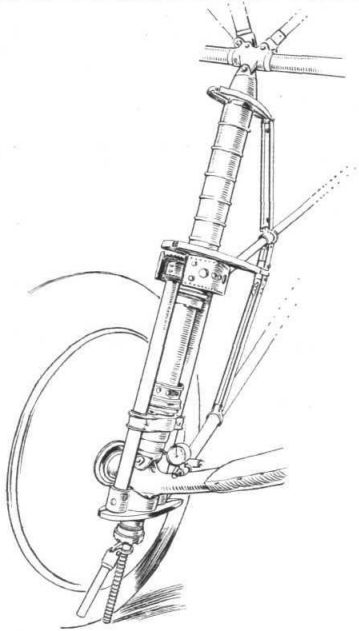
Flight 1928-03 / Flight
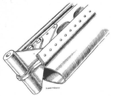
One of the undercarriage "legs'' of the Boulton & Paul "Sidestrand." The streamline fairing has been removed to show the arrangement.
-

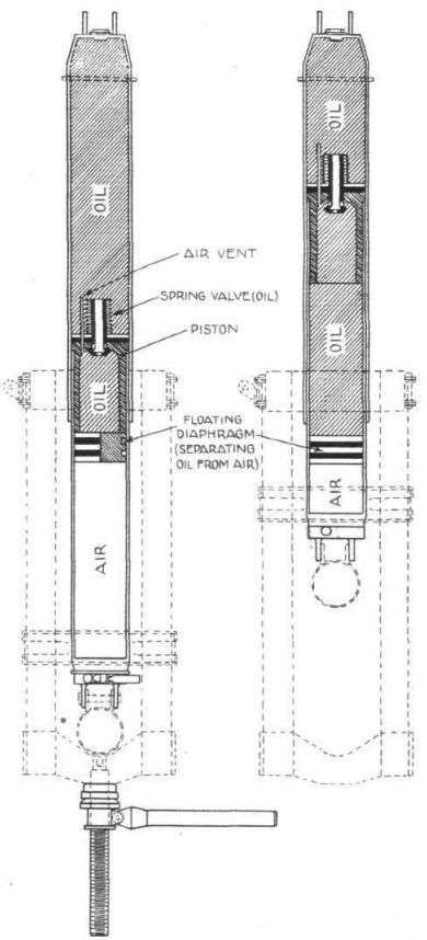
Flight 1928-03 / Flight
Diagrammatic representation of an undercarriage "leg" of the Boulton & Paul "Sidestrand I." The valve has a leak hole in its head, and ports in the tubular stem.
-

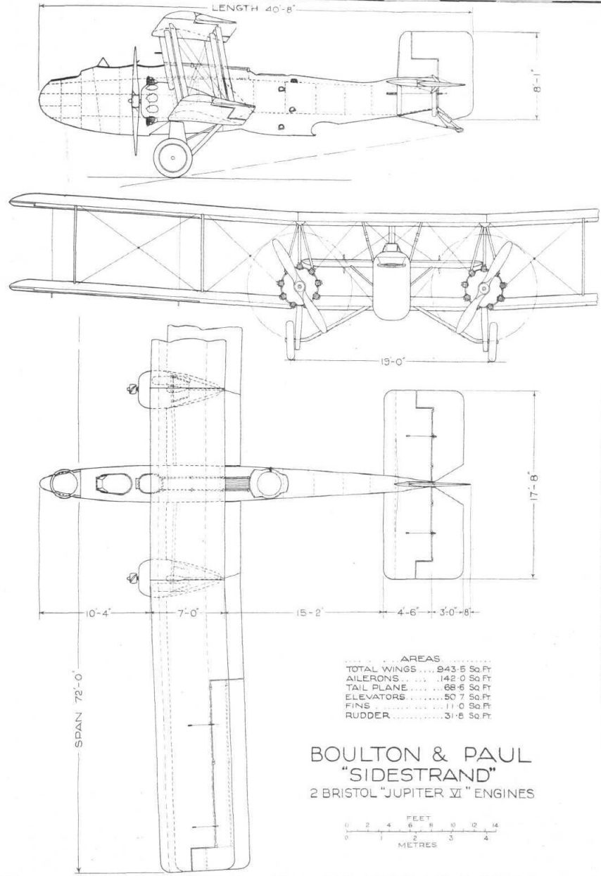
Flight 1928-03 / Flight
Boulton & Paul "Sidestrand" 2 Bristol "Jupiter VI" Engines
-

Flight 1929-07 / Flight
Boulton & Paul "Sidestrand" 2 Bristol "Jupiter VIII" Engines


- Фотографии