Boulton & Paul Р.25 Bugle
Хотя экспериментальный Boulton & Paul P.15 Bolton в серийное производство запущен не был, Министерство авиации в полной мере оценило совершенство этой цельнометаллической машины. Министерство решило оказать содействие фирме "Boulton & Paul" в развитии концепции цельнометаллического самолета, заказав постройку еще двух прототипов, получивших обозначение Boulton & Paul Р.25 Bugle. Внешне самолет напоминал цельнодеревянный Р.7 Bourges и цельнометаллический Р.15 Bolton, но его конструкция обладала рядом отличий.
Двигатели Jupiter монтировались на рамах, которые могли откидываться в стороны, давая доступ к задним частям моторов. В целях повышения безопасности полетов, Министерство авиации воспротивилось размещению топливных баков в фюзеляже. По два бака разместили под верхним крылом между фюзеляжем и моторами. Фюзеляж самолета стал более угловатым. Открытую кабину летчика разместили выше и сзади открытой кабины носового стрелка, обеспечив тем самым и пилоту, и стрелку отличный обзор.
Первый из двух Bugle Mk I выполнил первый полет 30 июня 1923 года, второй прототип собрали до конца года. После чего последовал заказ на изготовление третьей машины, также получившей обозначение Bugle Mk I и собранной в 1924 году с двигателями Jupiter IV мощностью по 436 л.с. Экипаж третьего самолета состоял из четырех человек, запас топлива в баках увеличили. Третий экземпляр передали в 25-ю эскадрилью британских ВВС для проведения сравнительных испытаний с самолетом Vickers Virginia. Машина показала сочетание хорошей управляемости с превосходной маневренностью. В 1924 году построили еще два прототипа Bugle Mk I, в целом аналогичных третьему прототипу.
В 1925 году построили два самолета - Р.25а Bugle Mk II с W-образными моторами Napier Lion мощностью по 450 л. с, установленными в мотогондолах на нижнем крыле. Топливные баки перенесли в фюзеляж, на бомбодержатели под фюзеляжем установили обтекатели. Предусматривалась постройка семи серийных машин, но британские ВВС отказались от них из-за сокращения финансирования.
ТАКТИКО-ТЕХНИЧЕСКИЕ ХАРАКТЕРИСТИКИ
Boulton & Paul Р.25 Bugle
Тип: дневной бомбардировщик с экипажем из трех человек
Силовая установка: два звездообразных мотора Bristol Jupiter III мощностью no 400 л. с.
Летные характеристики: макс, скорость на уровне моря 193 км/ч; время набора высоты 3050 м - 15 мин 30 с
Масса: пустого 2304 кг; максимальная взлетная 3680 кг
Размеры: размах крыла 19,83 м; длина 12,12 м; высота 4,78 м; площадь крыльев 86,58 м!
Вооружение: по одному 7,7-мм пулемету Lewis на носовой и надфюзеляжной турелях, бомбы на внешней подвеске под фюзеляжем и нижним крылом
Показать полностьюShow all
Flight, October 1922
THE BOULTON AND PAUL "BOLTON" (P.15)
Two 450 H.P. Napier "Lion" Engines
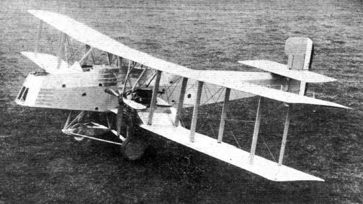
IN our issue of September 14, 1922, we published photographs of the new Boulton and Paul "Bolton" all-metal biplane (in skeleton), with two Napier "Lion" engines. On Friday of last week we paid a visit to the Boulton and Paul works at Norwich, where we had the privilege of examining the machine and of seeing it flown by Mr. Courtney. As the "Bolton" is built for the Air Ministry, but few particulars may be published, but the accompanying photographs, showing the machine after being covered will give a very good idea of the general lines. Concerning the really interesting features of the new biplane, i.e. the all-metal construction, nothing may be said, and the following notes therefore deal with the general design rather than with constructional details.
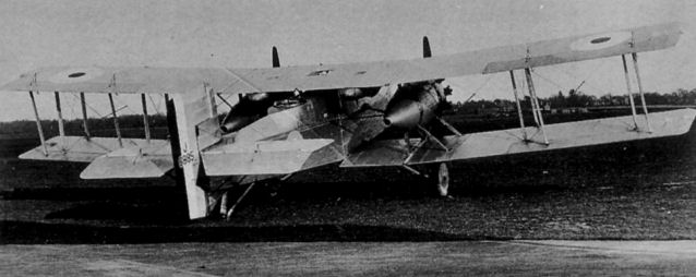
Although the "Bolton" bears a certain family resemblance to the famous "Bourges," it differs from the earlier machine not only in size, but also in several other important respects. The power plant consists of two Napier "Lion" engines, mounted fairly high in nacelles carried on the lower plane. As the question of efficient cooling is one about which comparatively little is known, it is of interest to note that in the "Bolton" the Napier engines are left uncovered to an unusual extent, with the consequence that radiators of relatively small size can be employed. A further advantage of this arrangement is that the exhaust silencers, which are of the patented Boulton and Paul type, with aluminium manifolds terminating in steel pipes having saw-cuts in them, are very efficiently cooled. In spite of their simplicity and lightness, these silencers are certainly very effective, as we had an opportunity of ascertaining, and it appears probable that the combination of exposed engines and small radiators offers no more resistance than enclosed engines with large radiators and complicated exhaust pipe arrangements.
Another feature noted in connection with the engines was the absence of vibration. When both engines were running all-out on the ground it was not possible to detect any vibration of the lower plane, a fact for which no doubt the special design of engine mounting is responsible. While on the subject of the engines, reference may be made to the unusual starting arrangement, which is one of the neatest we have seen so far. Instead of mechanics having to climb about on the machine in order to reach and turn the starting handle, arrangements are made in the "Bolton" for starting the engines from the ground, long shafts running from the engines, inside the nacelles, down to the tail end of the nacelles, where a starting handle can be inserted and the engines turned over by a mechanic standing behind the trailing edge of the lower plane. Not only is this position very comfortable and allows of maximum effort being applied, but should the mechanic slip his foot will not go through a plane or damage some important part, as is apt to occur in machines where the mechanic has to stand on a wing or other part.
The petrol system consists of main tanks mounted in the fuselage, with pumps (driven by windmills) constantly delivering to a feeder tank, also mounted in the fuselage, but at sufficient height to give gravity feed to the carburettors. Thus there is no petrol in the engine nacelles, while unsightly gravity tanks, externally mounted, are avoided.
The wings are of usual form as regards their external appearance, but are, like the rest of the machine, built entirely of steel, with exception of the covering, which is the usual doped fabric. It would of course, be possible to make the covering of metal also, but it is thought that the extra weight which this would entail would outweigh any advantage arising out of metal covering. The ailerons are of the type in which the hinges are placed some distance back from the leading edge, the balance being formed by the forward third of the aileron and not by a horn balance projecting forward outside the wing tip.
Several interesting features are incorporated in the tail. Thus in addition to the usual trimming tail plane, a trimming fin has been employed, which works in a manner similar to the trimming tail plane, its sideways displacement having, of course, for its object to equalise any turning moment set up by one engine developing less power than the other. As soon as the pilot discovers that one engine is dropping its revolutions, he turns a wheel in the cockpit and the fin moves over until the machine has no tendency to turn. The rudder is hinged to and moves over with the trailing edge of the fin.
The undercarriage is of a special oleo type, and from observation of the machine taxying and landing it would appear that the shock-absorbing qualities are extraordinarily good, no tendency to bouncing being noticeable. In addition to the two main wheels a third and smaller wheel is placed centrally and some distance ahead of the main undercarriage. This wheel prevents the machine from nosing over in a bad landing, and is partly enclosed in a streamline casing. It is sprung by rubber shock-absorbers.
Although the "Bolton" has not yet been thoroughly tested out, the few flights which have been made indicate that, when certain alterations which are always found necessary with new types, and which have, of course, nothing whatever to do with the metal construction, have been carried out, the new Boulton and Paul P.15 will be a very fine machine indeed. It appears to take off very quickly, and although on the occasion of our visit Courtney was not attempting to make rapid climbs, the machine appeared to get away very well, requiring but a very short run. Its landings also were very good.
We regret that no reference to constructional details is permitted, otherwise an illustrated article on the "Bolton" would, we feel certain, be of more than passing interest, the metal work being an extremely pretty piece of engineering and representing very great progress and advance over anything hitherto done in this or any other country. Time alone can show how metal will stand up to vibration, dampness, etc., but, as far as can be seen at present, there is no reason to suppose that it will give any unexpected trouble. We congratulate Boulton and Paul, and Mr. J. D. North, their chief engineer, on a very fine piece of work, and express the hope that they will continue their pioneer work on all-metal construction.
Показать полностьюShow all
Flight, April 1925
THE BOULTON AND PAUL "BUGLE”
Two Bristol "Jupiter" Engines
ALMOST from the very first, and certainly ever since they commenced to build machines to original designs, Boulton and Paul, Ltd., of Norwich, have specialised in high-performance twin-engined machines, a type which they have developed to a very high degree of perfection. First of the twin-engined machines to become generally known was the "Bourges," the first of which was, if we remember correctly, fitted with A.B.C. engines. One of these machines, it may be remembered, visited the Hendon aerodrome on the occasion of the welcome to the American transatlantic fliers, when Courtney's handling of it was the wonder of the day. Then followed a series of machines, among which descriptions and/or illustrations have appeared in FLIGHT of the "Bolton" with Napier "Lions," and the "Bodmin" with the same power plant, but with the engines placed in the fuselage, driving propellers on the wings through special gearing. Among the latest types of Boulton and Paul machines to which it is permissible to refer in detail is the "Bugle," with Bristol "Jupiter" engines. Even this is not the most recent type, but concerning its later developments it is not possible to write owing to Air Ministry restrictions.
It will be recollected that it is now several years since Boulton and Paul disposed of all their woodworking machinery (as far as the aircraft section is concerned), and turned their attention to all-metal construction. The first "Bourges" were of usual wood construction, but shortly afterwards the works were converted for metal work solely, and the "Boltons," "Bodmins" and "Bugles" are all built entirely of metal, mainly steel, a form of construction upon the development of which this firm must have spent very large sums of money. The result has, however, been that Boulton and Paul are now acknowledged to hold a leading position, not only in this country but probably in the world, in steel construction of aircraft. Mr. J. D. North, chief engineer and designer, his assistant Mr. Bennell, and a highly-skilled staff of specialists in various branches, have developed methods of rolling high-tensile steel strip into remarkably efficient sections, joined together by riveting, and not the least important progress made has been that connected with protecting the extremely thin steel strip against corrosion. There appears to be reason to believe that means have now been found which will prevent serious corrosion, and that therefore the special forms of construction which have been developed may be employed with confidence as regards the problem of corrosion.
On previous occasions detailed reference has been made to the special forms of metal construction developed by Boulton and Paul, and it is not, therefore, intended to repeat these here, but rather to devote such limited space as is available this week to the "Bugle" as a whole, and to such features as were not to be found in machines previously described.
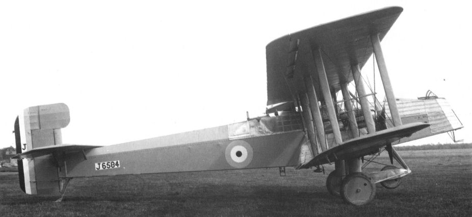
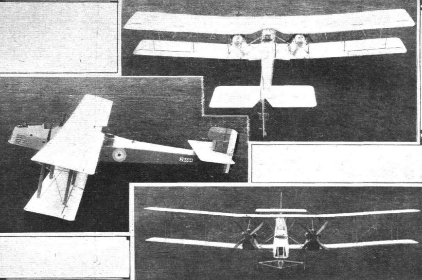
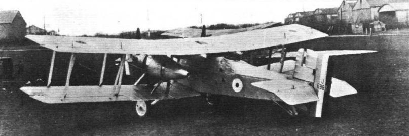
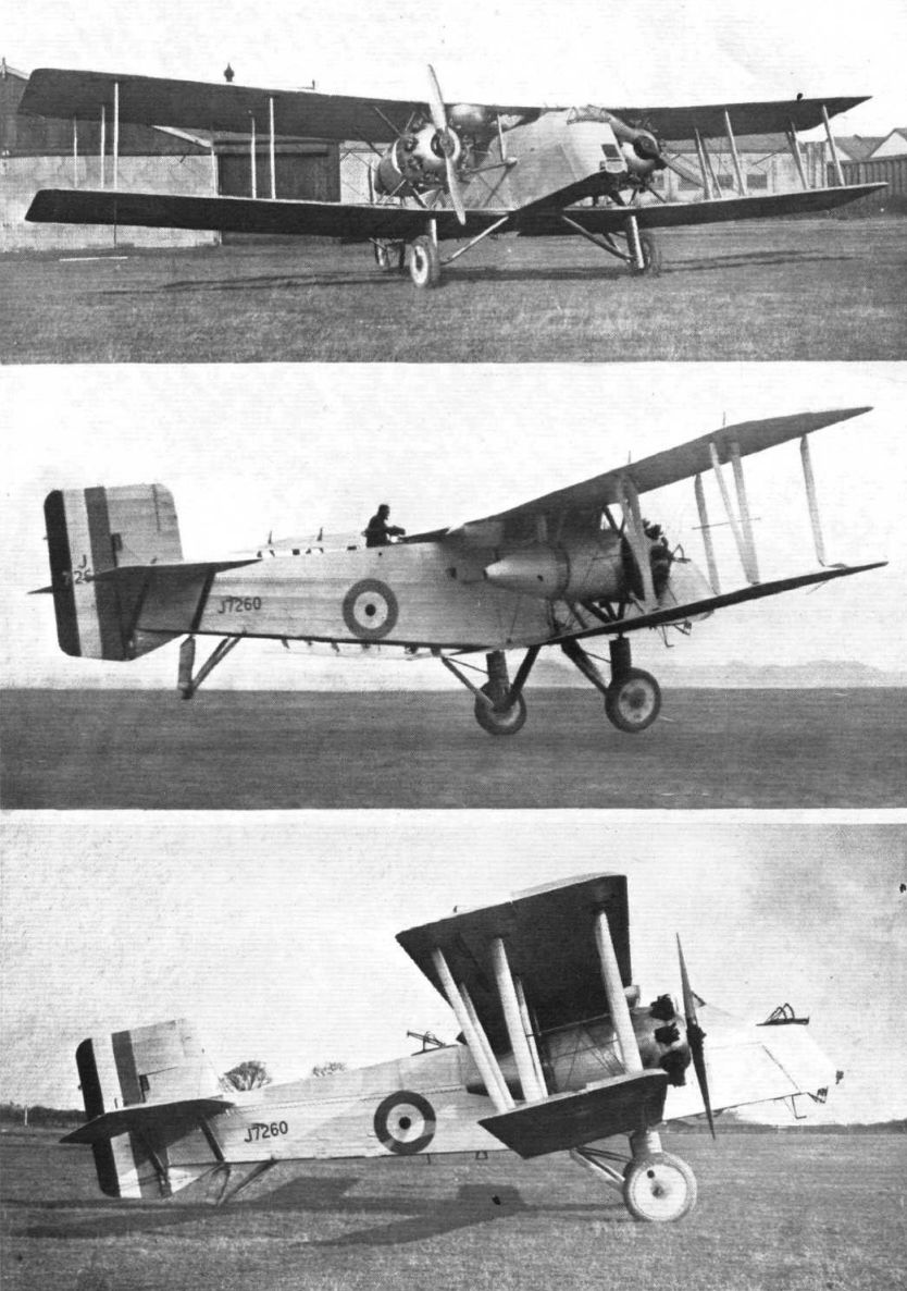
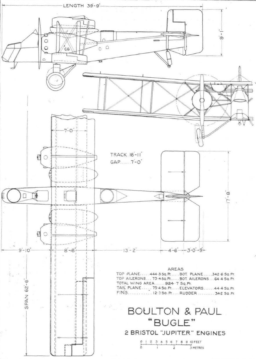
The Boulton and Paul "Bugle" bears a very strong general family resemblance to the "Bourges" and subsequent types, although differing from them in many important respects. The machine is a twin-engined tractor biplane with the Bristol "Jupiter" engines mounted in the gap between the wings on tubular engine structures. As in most Boulton and Paul machines, the lower plane is of somewhat smaller chord than the upper, and the aspect ratio is relatively high, i.e., in the neighbourhood of 8. The wings are of rectangular plan form with the corners rounded off. Ailerons are fitted to both upper and lower plane, and are balanced by projections working in cut-outs in the main wing tip. The balances are not symmetrical, but have a fairly flat bottom camber and a deeper top camber, the lower wing curve following the contour of the wing section (R.A F. 15) when the aileron is in the neutral position.
The tail is of normal type, with trimming tail plane and unbalanced elevator. The rudder, however, has a very large balance, working in a cut-out in the fin. The area of the balance is a very large percentage of the rudder area, and would normally cause over-balancing. Since, however, the balance works in an area sheltered by the fin, it does not commence to work until well clear of the fin, and thus for ordinary turning the presence of the large balance does not upset the pilot's steering as it otherwise would. That the rudder and its balance is effective will be realised when it is pointed out that it is actually possible to switch one engine off and to fly not only straight, but actually turning towards the running engine, overcoming the turning moment. Locking devices are incorporated in the rudder operating gear, which enable the rudder to be set permanently over to one side or other while still retaining the movement of the rudder to a sufficient extent. As a matter of fact, a better description than locking device would be spring-loading device, for, of course, the rudder is not definitely locked; what happens is that levers on each side set the rudder bar to any desired angle, according to the difference in thrust of the two engines, and springs incorporated in the gear enable a further movement to be made. Finally, there is, in the extreme nose of the fuselage, a small hand-wheel operated by the bombing officer, by which very fine adjustment of the rudder is made. This gear forms, as it were, a vernier adjustment of the rudder, and when operative works independently of the pilot. The question of form, size and disposition of the control surfaces of the "Bugle" have been very carefully gone into, with the result that the machine is stated to handle particularly nicely, and to fly very slowly while still being under perfect control.
While on the subject of controls, mention should be made of the fact that the ailerons are mounted in self-aligning ball bearings, so that a slight deflection of the wing spars does not cause them to work stiffly, and as a matter of fact, the ailerons, in spite of their large area, are remarkably easy on the controls and require surprisingly small effort on the part of the pilot, a fact of great importance during a long flight.
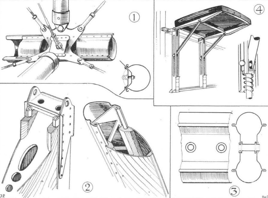
Constructionally, the "Bugle" is of fairly normal Boulton and Paul type. An exception is found in the attachments of the inter-plane struts which are now secured to plates straddling the spars. The spars are always in the plane of the wing bracing, and there is thus no offset torque moments. The struts themselves are of highly interesting construction, and are built either in steel or in Duralumin. The inner and more highly-stressed struts are of fairly heavy gauge steel. Less severely loaded struts are of thinner gauge steel, while the most lightly loaded struts are of Duralumin. Thus, with the same section a wide range of strut strengths is available. One of our sketches shows how the struts are built up, and is self-explanatory. The struts can be built of smaller width for the same strength as a tubular strut, or, conversely, for the same width and resistance will be stronger. The fairing is of three-ply wood, and is extremely light. It is slid over the projecting edges of the strut, so that after use the fairing can be slipped off and the strut examined if desired. We believe this strut construction is protected by a patent.
The Bristol "Jupiter" engines are mounted on tubular structures in the gap between the wings, and each engine is attached to the main engine structure by a swivelling mounting patented by Boulton and Paul several years ago. This mounting facilitates access to the back of radial engines, and conical or tapered bolts are used so as to take up any wear that might take place. The engines and their supporting structures are enclosed in almost perfect streamline casings, as will be seen from the photographs. The fuel supply is by direct gravity feed, there being two petrol tanks, one for each engine, supported underneath the top plane. The tanks also are visible in the illustrations.
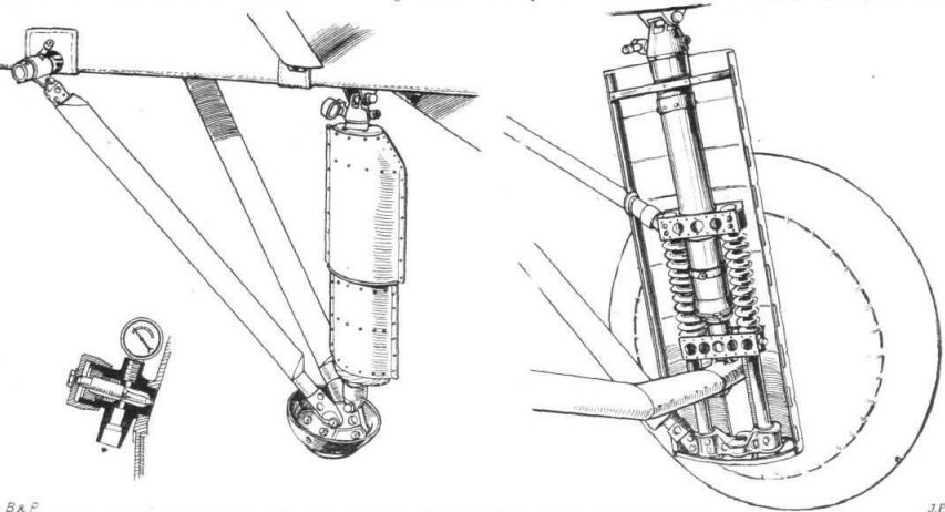
The oleo undercarriage fitted on the "Bugle" is of particularly robust construction, and has been designed to give exceptional shock-absorbing qualities. It has not been found possible to give a sectional drawing of one of the "legs," but a sketch shows the external appearance, and, with a few words of explanation, may serve to indicate the general principle.
The oleo-pneumatic leg consists, as usual, of two tubes, one of which telescopes inside the other. The lower tube in this case passes inside the upper, and carries at its upper end a piston with small leak holes, and also a spring-loaded valve opening downwards. The lower tube passes, of course, through a stuffing-box in the lower end of the upper tube. Inside the upper, larger-diameter tube, near its upper end, is a diaphragm bolted to the walls of the tube and having leak holes and a spring-loaded valve opening upwards. The tube is filled with oil up to just above the diaphragm, and air is pumped into the space above the oil to the required pressure. This, of course, is done with the leg fully extended. A neat air pressure gauge is fitted in the upper end of the tube, and has a needle valve arrangement for placing the gauge out of circuit when the undercarriage is in use. A jack is then placed under the undercarriage and the machine raised until the leg is extended. The pressure employed is, we believe, 60 lbs. per square inch, and when this pressure has been obtained, the needle valve is screwed down on its seating, and the gauge thus cut off from communication with the inside of the tube.
A somewhat similar telescopic leg is employed for the tail skid, and actually the machine can land and touch with the skid first without causing any damage, so that there does not appear to be much doubt about the shock-absorbing qualities of this form of oleo-pneumatic leg.
It is regretted that performance figures may not be published, otherwise it would, we think, be obvious that in the “Bugle" Mr. North has reached a very high performance for a machine designed to carry all sorts of "frightfulness," in addition to a crew of three and fuel for a very large cruising range. This is due, in some measure, to the all-metal construction, which enables a not inconsiderable saving in structure weight to be made, but also to careful aerodynamic design in so far as this is possible in a machine which must have all manner of excrescences dictated by military considerations. The wing section is the ubiquitous R.A.F. 15, but the aspect ratio is high, about 8, and careful streamlining has been carried out wherever possible, such as to undercarriage legs, tail skid telescopic leg, and, of course, to the engine housings. Incidentally, it may be of interest to mention that the Boulton and Paul aerodynamics staff has now commenced to calculate wing sections on the Joukowsky-Prandtl theory, and have verified certain sections by wind tunnel tests. The agreement between calculated and experimentally determined values has been found to be excellent.
Показать полностьюShow all