

 Wiki
Wiki 
Jane's Encyclopedia of Aviation
Langley Aerodrome (USA)
The full-size Aerodrome was a tandem-wing aeroplane powered by a 38.75 kVV (52 hp) Manly radial engine driving two 2.67 m (8 ft 9 in) propellers. Wing span was 14.63 m (48 ft in).
Описание:
- Jane's Encyclopedia of Aviation
- Flight, October 1921
THE LANGLEY MACHINE AND THE HAMMONDSPORT TRIALS
Фотографии
-
Aviation Historian 14
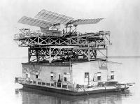
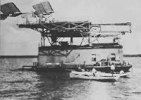
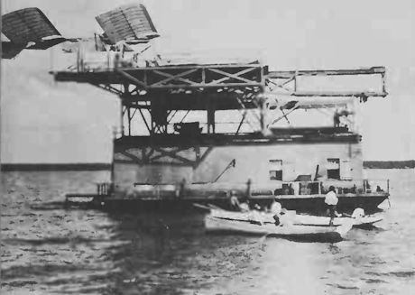
Langley Aerodrome, seen atop its houseboat "carrier” on the Potomac river in 1903.
-
Jane's All the World Aircraft 1980 / Encyclopedia of Aviation - 1. Chronology
Langley’s Aerodrome (7 October 1903).
-
Aviation Historian 11 / N.Engler - Politically Incorrect
Неудачный старт аппарата "Аэродром" С.Ленгли с баржи на р.Потомак
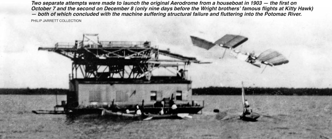
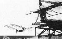
Two separate attempts were made to launch the original Aerodrome from a houseboat in 1903 - the first on October 7 and the second on December 8 (only nine days before the Wright brothers’ famous flights at Kitty Hawk) - both of which concluded with the machine suffering structural failure and fluttering into the Potomac River. -

Aviation Historian 11 / N.Engler - Politically Incorrect
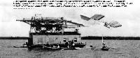
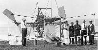
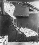
Samuel Langley (furthest left) supervises preparations for the launch of the original Aerodrome from the roof of a houseboat in 1903. Despite both attempts ending in a dunking for the pilot, Charles Manly, Langley continued to insist that the aircraft was airworthy, but had failed owing to a defect in the launching apparatus.
-

Aviation Historian 14
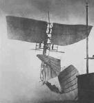
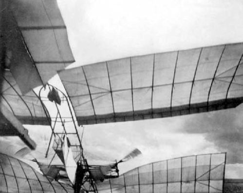
The moment of launch - Langley machine viewed from below, front wings twisted and bent against framework.
-
Jane's All the World Aircraft 1980 / Encyclopedia of Aviation - 1. Chronology
The Aerodrome breaks up and drops into the river (8 December 1903).

-

Aviation Historian 11 / N.Engler - Politically Incorrect
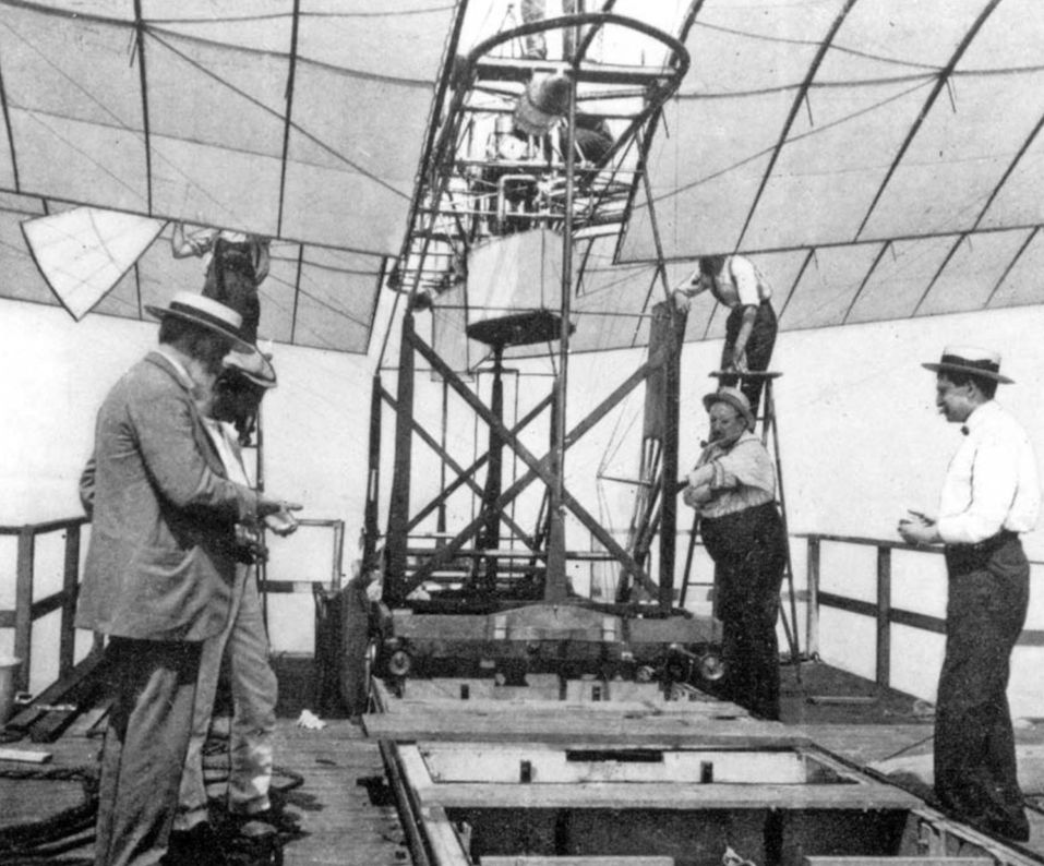
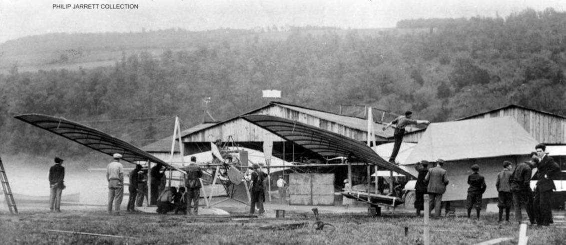
Meddling with history - Curtiss engineers work on the first-stage reconstruction of the Langley Aerodrome at Hammondsport in 1914. The original 1903 Aerodrome had no undercarriage, unlike the reconstruction, which sported pontoons as seen here, and was considerably flimsier than its 1914 iteration.
-
Aviation Historian 11 / N.Engler - Politically Incorrect
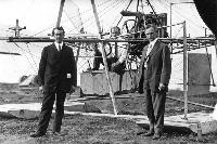
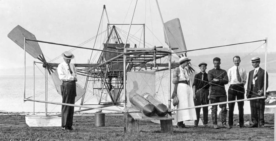
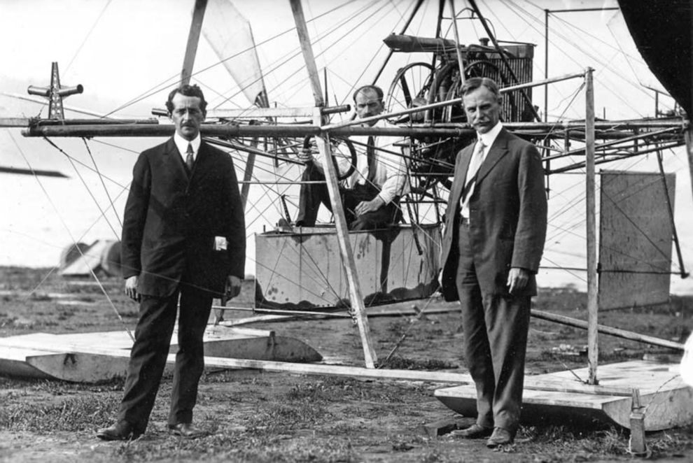
Charles Doolittle Walcott (furthest left) contemplates the incomplete Aerodrome at Hammondsport in 1914. Other members of the group include Albert F. Zahm (furthest right), Glenn Curtiss (second from right) and Walcott’s daughter Helen. Note the automobile-type radiator which replaced the finned tubes on the 1903 original.
-
Aviation Historian 11 / N.Engler - Politically Incorrect
From L to R: Messrs Manly, Curtiss and Zahm;
-
Aviation Historian 11 / N.Engler - Politically Incorrect
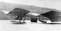
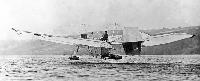
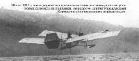
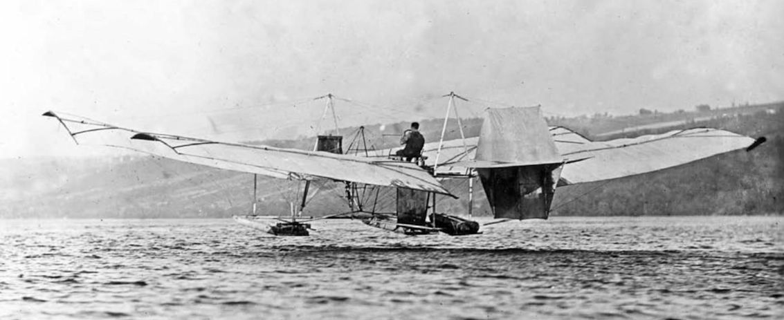
Showing the merest glimpse of air beneath its pontoons, the much-modified Aerodrome lifts from the surface of Lake Keuka on June 2, 1914, with Glenn Curtiss at the controls. The fixed tail surface was altered to become a movable rudder during the first set of modifications and a large underfuselage rudder was also fitted.
-
Aviation Historian 11 / N.Engler - Politically Incorrect
The Aerodrome was modified yet again, even more radically, for more flights from Lake Keuka later in 1914. The pilot’s position was completely relocated atop the wings and further aft and, significantly, the original engine and twin pusher propellers were replaced with a modern 80 h.p. Curtiss engine driving a single tractor propeller.
-
История Авиации 2002-04 / С.Корж - Коммерческая авиация /Ретроспектива/ (3)
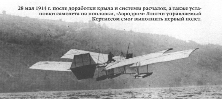
28 мая 1914г. после доработки крыла и системы расчалок, а также установки самолета на поплавки, "Аэродром" Лэнгли управляемый Кертиссом смог выполнить первый полет.
-
Aviation Historian 11 / N.Engler - Politically Incorrect
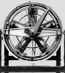
BASED ON A design by New York-based engine builder and former Tiffany’s watchmaker Stephen Balzer and co-developed with Langley’s assistant Charles Manly, the five-cylinder water-cooled radial engine that powered the original 1903 Aerodrome, the world’s first purpose-designed aircraft engine, was a remarkable piece of engineering for its day. Originally fitted with a Balzer carburettor consisting of a chamber filled with lumps of porous cellular wood saturated with gasoline, through which air was drawn, the engine was modified for the 1914 flights (as seen here) with an automobile-type carburettor with a float feed. The original radiator, made up of tubes with radiating fins, was also replaced, with a car-type “honeycomb” radiator.


-
Мировая Авиация 32
Аппараты Aerodrome Лэнгли. 1896: американский математик и физик Сэмюэль Пирпонт Лэнгли (родился в Массачусетсе в 1834 году, умер в 1906-м) осуществил первый подтвержденный полет беспилотного летательного аппарата тяжелее воздуха. Модели планеров Aerodrome 5 с размахом крыльев 4,25 м (на фото) и Aerodrome 6, запущенные со второго этажа плавучего дома на реке Потомак возле Куантико, набирали высоту до 1280 м. Каждая модель была оснащена паровым двигателем, установленным в средней части фюзеляжа и приводившим во вращение два воздушных винта. В 1898 году Лэнгли получил государственную субсидию $50000 на разработку полномасштабного летательного аппарата Aerodrome с размахом крыльев 14.6 м, который был закончен к 1903 году.
-
Мировая Авиация 32
Модель планера Aerodrome 5 с размахом крыльев 4,25 м
-
Aviation Historian 14
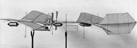
Samuel Pierpoint Langley’s model of his Aerodrome, which he simply scaled up in order to create the full-size aircraft
-

Aeroplane Monthly 1988-12 / P.Masefield - Wren
One of Wren's early illustrations appeared in the January 1933 issue of W. E. Johns’ Popular Flying magazine. Though he had already developed a style as a caricaturist, there is no evidence of it in this artwork.
-

Aviation Historian 11 / N.Engler - Politically Incorrect
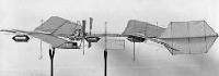
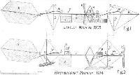
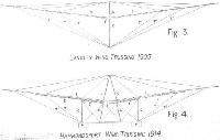
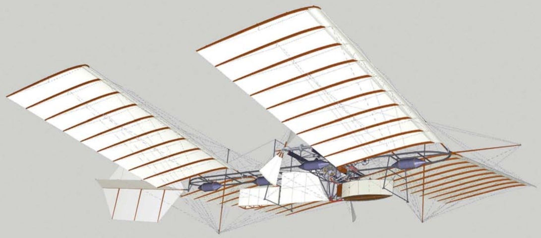
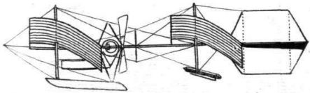
The Langley Aerodrome in its original 1903 configuration. This is the first of three detailed artworks by the author, showing the 1903 and 1914 versions of the Aerodrome, plus a composite which highlights the differences. All three are available as free interactive downloadable 3D PDFs via our website at www.theaviationhistorian.com
-
Aviation Historian 11 / N.Engler - Politically Incorrect
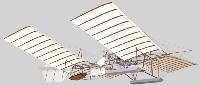
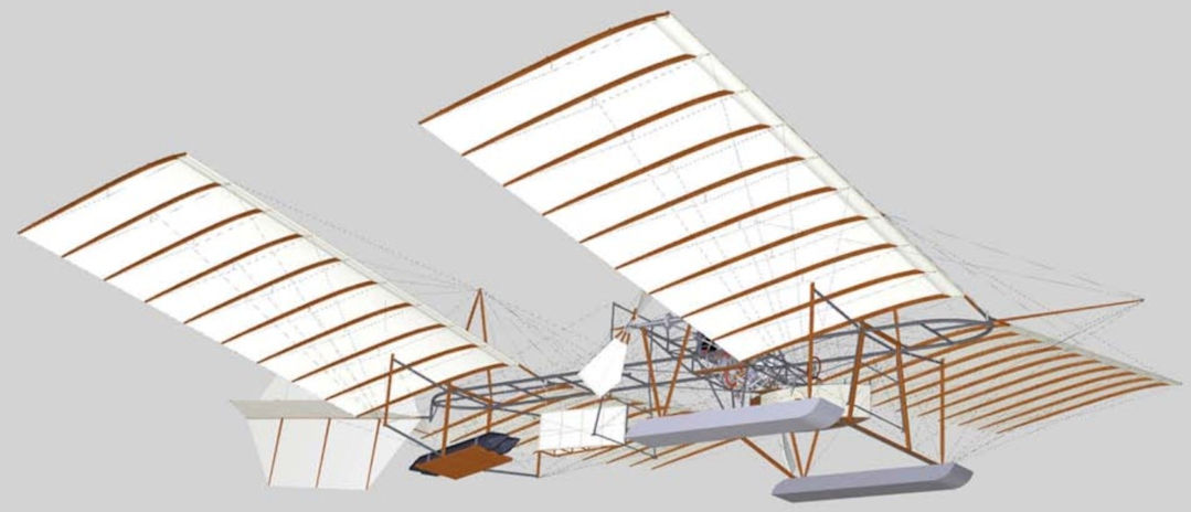
Looking at first glance very similar to the 1903 Aerodrome, except for the floats, this artwork shows the aircraft in its May-June 1914 configuration, with revised bracing, narrower-chord wings, pontoons, reinforced spars and ribs and other changes including the propeller blades, reshaped in an effort to increase thrust.
-
Aviation Historian 11 / N.Engler - Politically Incorrect
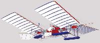
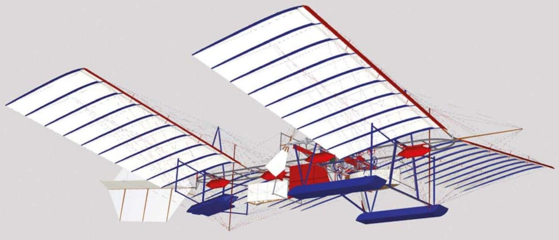
In this composite artwork, the parts of the Aerodrome that were removed in 1914 are shown in red and those that were added or modified are shown in blue. Apart from the addition of the pontoon floats replacing the original small flotation-aid tanks, note especially the deletion of the 19ft2 (1.76m2) central fabric “keel” surface.
-
Aviation Historian 11 / N.Engler - Politically Incorrect
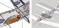
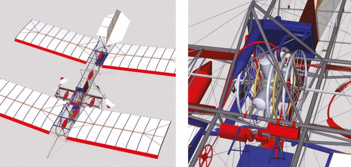
LEFT Looking down into the cockpit “boat” from a viewpoint just above the 1903 Aerodrome, this image shows the twin-“trimwheel” controls, and the original ignition system. RIGHT This front three-quarter view of the 1903 version shows the frail kingpost bracing system and the original helical propeller-blade shape.
-
Aviation Historian 11 / N.Engler - Politically Incorrect
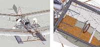
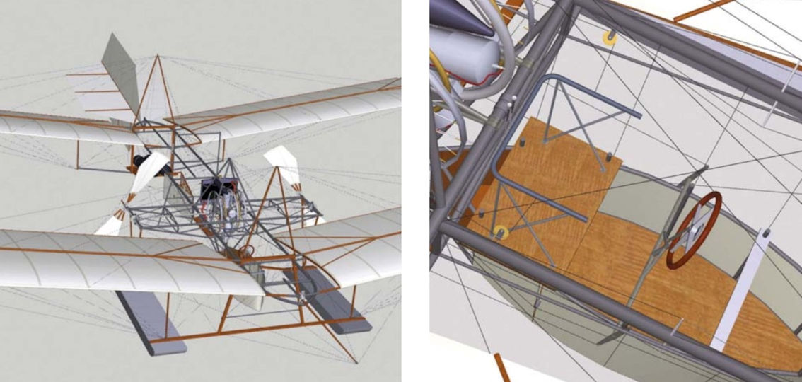
LEFT Rotating the 3D artwork of the 1914 version to a more frontal view reveals the sturdy A-frame wing struts and associated float struttery. RIGHT The 1914 cockpit. Note the conventional wheel for pitch and yaw control; the pilot would use a Curtiss shoulder-yoke for roll control, hence the seat-rail for him to bear against.
-

Aviation Historian 11 / N.Engler - Politically Incorrect
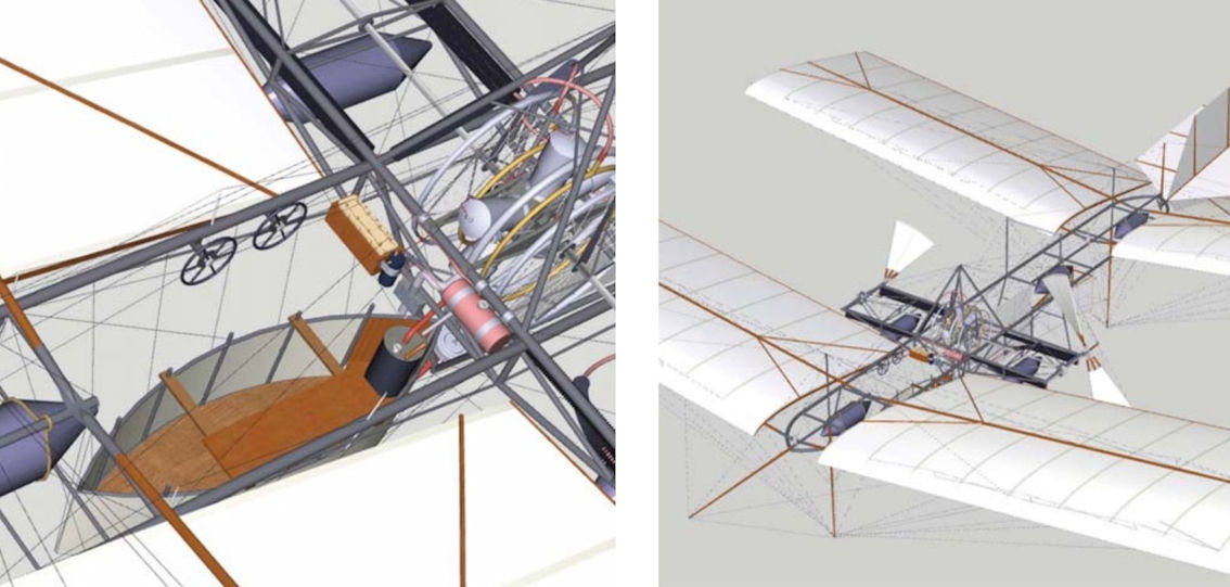
LEFT The truncation of the wing leading edges (seen in red) increased the aspect ratio and reduced the camber. RIGHT Zooming in on the Manly-Balzer engine installation shows how the finned-tube radiators were replaced by a more conventional unit. Download all these 3D artworks from our website to explore them fully.
-
-
-
Flight 1935-03 / Flight
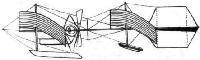
Langley's tandem-winged machine of 1903.


- Фотографии