Sablatnig. Самолеты
<...>
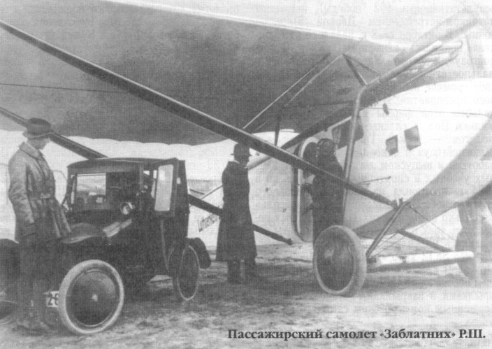
За Р I последовал более удачный высокоплан Р III - летчик размещался в открытой кабине, а в закрытой кабине помещалось шесть пассажиров. Р III поставлялись авиакомпаниям «Aeronaut», «Danish Air Express», «Deutsche LuftHansa» и «Lloyd-Luftverkehr Sablatnig», а также BBC Швейцарии. В 1921 году фирма прекратила существование.
Показать полностьюShow all
Flight, August 1921
THE SABLATNIG P. 3 MONOPLANE
Germany's First Commercial Aeroplane
As probably the first aeroplane designed especially for commercial work, the Sablatnig occupies a position in Germany somewhat similar to that of Fritz Koolhoven's B.A.T. F.K.26 in this country. Like a good many other firms, Sablatnig commenced with a converted war machine, the Sab. P.1. This machine was a biplane of more or less orthodox wartime design, but had a conservatory roof added over the front cockpit. On this machine a flight was made from Berlin to Copenhagen and Stockholm on May 11, 1919. Like other converted war machines, the Sab. P.1 suffered from inadequate passenger accommodation, and hence it was soon decided that the type was not worth going on with. Dr. Sablatnig then set to work to design a machine which should possess such features as would make it a commercial proposition. The result was, first, the Sab. P.2, which was not, however, considered entirely suitable, and a second attempt was made, resulting in the construction of the Sab. P.3, which is the subject of the present description and illustrations.
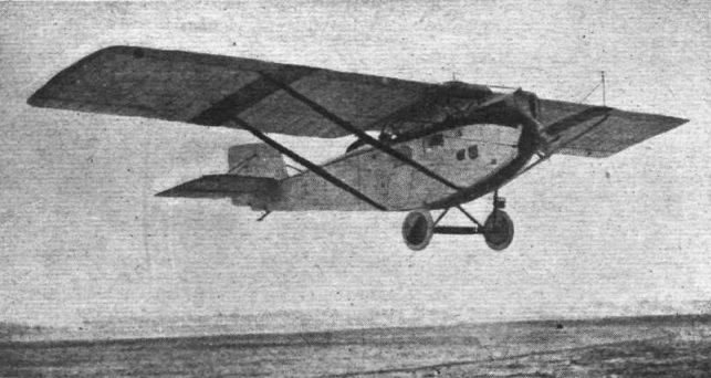
General Arrangement
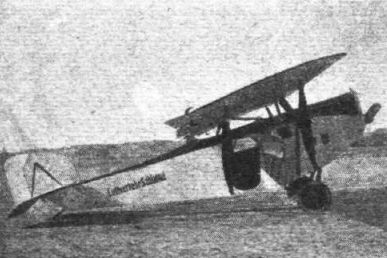
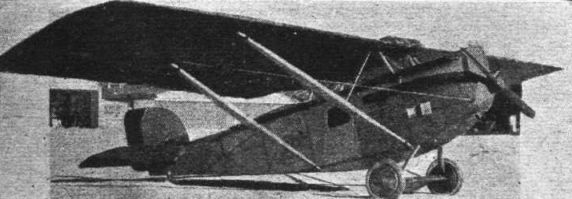
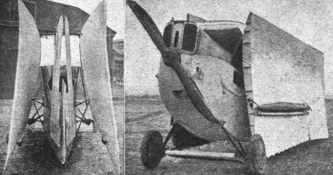
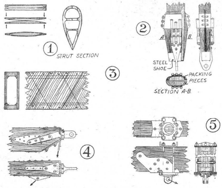
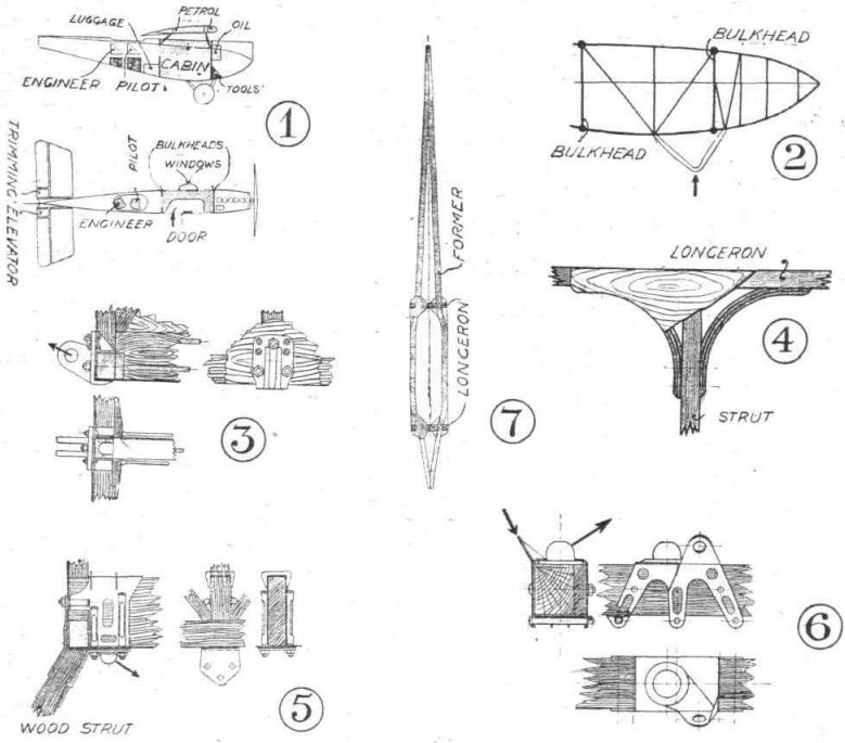
As will be seen from the accompanying illustrations, the Sab. P.3 is a parasol monoplane with a very simple form of strut bracing, in which it differs from the majority of German monoplanes, which are often of the cantilever wing type. Dr. Sablatnig's reason for adopting a braced wing may be partly to save weight, but is more probably dictated by the desire to provide wings which fold fiat against the sides of the fuselage, an arrangement which would not be possible with a one-piece cantilever wing. Having decided to have folding wings, the problem was to provide the simplest form of bracing so that the wing could be dismantled in the shortest possible time. The form which the bracing has taken will be seen from the illustrations: On each side there is one pair of struts, running from the lower longerons of the fuselage to the wing spars at points slightly nearer to the wing tips than to the root. There is no "incidence" bracing between these struts, but an external drag wire runs to the nose of the fuselage from the point of attachment of the rear strut to the rear wing spar. It would appear to be somewhat doubtful whether this bracing is capable of giving sufficient rigidity, and one would rather expect that the wing might be liable to a considerable amount of deflection, and especially torsion, during flight. However, we are not aware that in practice this has been found to be so. The manner of building up the wing struts is of more than passing interest, as it appears to be identical with the method invented and patented in this country by Mr. Fairey during the War. As the illustration will indicate, the struts are made of two halves, the inner faces of which are rounded off and the ends forced together, thus putting an initial tension on the outer fibres of the wood. Mr. Fairey has found that such a strut is very much stronger in compression than one made in the usual way, although it would probably be a matter of some difficulty to give satisfactory proof of the why and wherefore. Certainly the outer fibres will not begin to become loaded in compression until a fair load is on the strut, and thus the zero load point occurs at an actual load of so many pounds. On the other hand, the inner fibres are put into compression in making the strut, and might thus be expected to fail earlier than if the two halves had not been stressed originally. However, the fact remains that struts made in this manner have been found to give very good results. Probably Mr. Fairey himself did not originally realise the full advantage of such struts, as he does not appear to have taken out a patent in Germany.
From the illustrations it will be seen that the front strut of the Sablatnig is steadied in the centre by a tube running up to the front spar of the centre-section. It would therefore appear that, even with the special strut construction employed, a strut of this length cannot be relied upon to take compressive loads of great magnitude, such as might occur when there is a down-load on the front spar in a steep dive. The problem of a good terminal attachment for these struts is also one of some importance, owing to the change in direction of the load. Fitting ordinary eyebolts into the wood spar would scarcely be satisfactory, as such a bolt might, and probably would, work loose in the wood and give rise to "play." A similar argument applies to the strut fitting itself, and it is therefore not without interest to examine how Dr. Sablatnig has attacked the problem.
The spar fitting by means of which the lift struts are secured, is shown in one of the drawings. First of all a sheet-steel stirrup fits over the lower face of the spar, to which it is secured by horizontal bolts. In order to prevent the tightening up of these bolts from bending the relatively thin sheet steel and thus crushing the wood, it appears that metal bushes are housed in the three-ply sides and spruce fillers of the spar at this point, as indicated in the section of the spar and fitting. This stirrup plate forms a base plate for the swivelling fork-end, which has a circular base working in a cup formed in the second sheet-steel plate. The latter is held to the stirrup plate first by rivets, and later the whole is held together by four long bolts passing up the sides of the spar and through a flanged plate on top of the spar. Incidentally this latter plate serves as the attachment, when the wing is folded, of the rear spar to the tubular pyramid on the fuselage.
As regards the fitting for the lower ends of the lift tubes, this will be dealt with under fuselage construction. The fitting on the ends of the lift struts themselves is an elaborate affair, necessitated by the fact that the struts may be called upon to work in tension as well as in compression. Perhaps it will best be understood from an inspection of the accompanying drawings. The compression loads are taken on a steel shoe at the extreme end of the strut. For tension loads there is a forged fitting, divided so as to pass up some distance on each side of the strut. This forging is attached to the strut by horizontal bolts passing through fitting and strut. An ingenious method has been employed for preventing this fitting from pulling off, and for this reliance has not been placed upon the horizontal bolts. Packing pieces of wood are glued on to the front and rear of the strut end in such a manner as to form a cone. Resting on this cone is a sheet-steel fitting made in two halves, which grip the cone fairly tightly. Short tubular lugs are welded on to the sides of the sheet-steel upper fitting and similar ones, presumably forming part of the forging, are provided on the sides of the forked lug. Long vertical bolts pass through these lugs so that, should any slack develop, which is scarcely likely owing to the fact that the upper fitting would tend to be drawn tighter and tighter on to the wood cone, it can be taken up on the vertical bolts without interfering with the strut, probably even without removing it from the machine. The fitting looks somewhat clumsy, but gives the impression of immense strength, although the welding on of tubular lugs for the long bolts would appear to be a possible source of weakness.
<...>
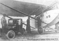
Crew and Passenger Accommodation
As will be seen from the diagrams of the fuselage in side elevation and plan, the pilot is seated relatively far aft, much as in the B.A.T. F.K.26. The cockpit is a fairly large one, and has space behind the pilot for a seat for the mechanic, or, if one is not carried, for a passenger. This seat is slightly staggered in relation to that of the pilot, in order, no doubt, to provide better leg-room within a small space. In the bulkhead in front of him there is a small window. Under the pilot's feet is a small compartment for luggage, while in front of that again is the aft bulkhead of the cabin. The latter is of large proportions for the size of the machine, and has room for six passengers. These are seated, so far as can be gathered, on one long seat running lengthwise along the port side of the cabin, so that if it is desired to carry a patient he can lie full length, while there is still room in the cabin for attendants. The seat is easily removable if it should be desired to use the cabin space for goods. It is even stated that it is possible to get an aero-engine through the door of the cabin, should it become necessary to transport one in a case of urgency.
In addition to the luggage space behind the cabin, there is a small compartment just in front of the forward cabin bulkhead in which can be stored such tools as may be required for repairs or adjustments en route.
Some Special Features
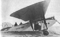
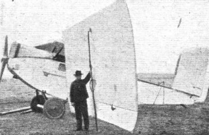
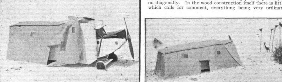
IT has already been described how the wings are quickly folded for transport or storage. In the folded condition the Sab. P.3 is so proportioned that it will just go into a German railway truck. On the other hand it might be desirable to carry a hangar on board, in case the machine should be used under conditions which precluded the use of ordinary sheds. For this purpose a small tent has been made which just fits the machine, as shown in the photographs. Owing to the fact that the leading edge of the wings is turned upwards when the wings are folded, it has been possible to avoid the necessity for any tent poles whatever, the leading edges of the two halves of the wing being strong enough to support the tent roof. This tent, which is provided with a door flap and with celluloid windows, weighs about 85 lbs. complete, and is not, therefore, a serious addition to the weight when the machine is used for special work where other accommodation is not available.
For use in winter, experiments - successful we believe - have been made with fitting the Sablatnig with skis, as illustrated in two of the accompanying photographs. This ski undercarriage is so designed as to fit on to the wheel axle instead of the wheels without entailing any other alteration than the substitution of skis for the wheels. The chassis struts and axle remain undisturbed. For use in countries where the ground is covered with snow for a considerable period of the year this undercarriage should be very serviceable.
Altogether the Sablatnig P.3 is a very interesting machine, and, it might be added, one of the few which have been passed by the Inter-Allied Commission.
Following are the main characteristics of the machine :-
Length o.a. 29 ft. 4 ins
Span 52 ft. 6 ins.
Height 10 ft. 8 ins.
Area 485 sq. ft.
Engine 200 h.p. Benz or 260 h.p. Maybach
Weight empty (Benz) 2,940 lbs.
,, ,, (Maybach) 3,080 lbs.
Useful load 1,870 lbs.
Total weight (Benz) 4,810 lbs.
,, ,, (Maybach) 4,950 lbs.
Weight per h.p. (Benz) 24 lbs.
,, ,, (Maybach) 19 lbs.
Speed 93 m.p.h.
Показать полностьюShow all


 Wiki
Wiki