Saunders. Ранние летающие лодки
Судостроительная компания "S. Е. Saunders Ltd" из Кауса, остров Уайт, стала известной благодаря изготовлению легких и прочных корпусов для скоростных катеров. Это достигалось с помощью разработанного компанией материала "Consuta", представлявшего собой фанеру, армированную медной проволокой. Материал идеально подходил для корпусов летающих лодок и поплавков. В 1912 году был построен гидросамолет Sopwith Bat Boat No.1, сочетавший бипланное крыло с корпусом из материала "Consuta".
В годы Первой мировой войны компания занималась выполнением контрактов для более крупных фирм. Вскоре после окончания боевых действий было принято решение заняться разработкой гидросамолетов собственной конструкции.
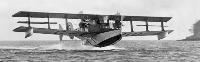
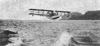
Первым заметным проектом фирмы стала летающая лодка Saunders Kittiwake. Это была амфибия, построенная по схеме биплана и рассчитанная на перевозку семи пассажиров и двух членов экипажа.
По всему размаху крыльев имелись поверхности для изменения кривизны профиля, улучшавшие управляемость на малых скоростях, так что элероны пришлось разместить между стойками бипланной коробки.
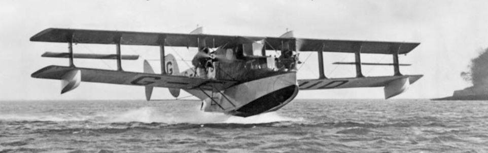
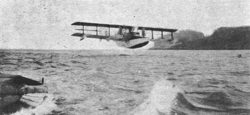
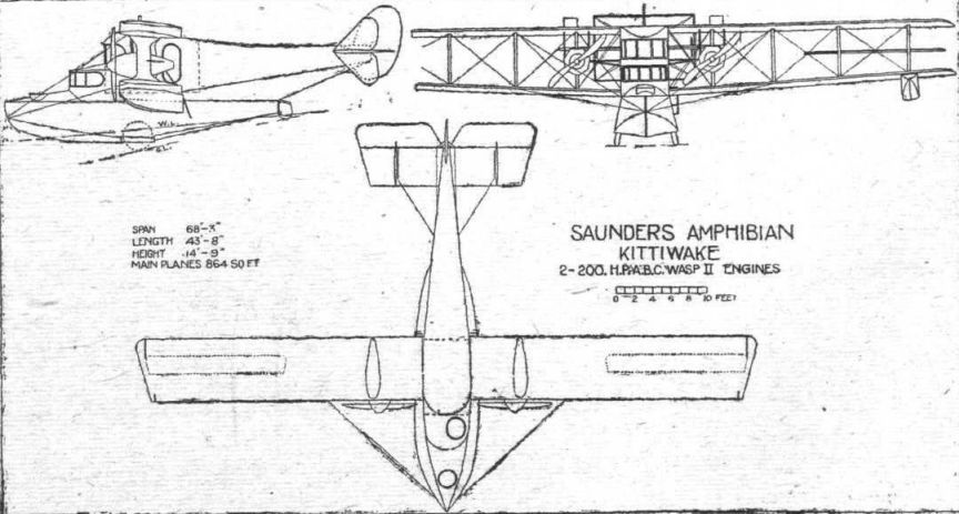
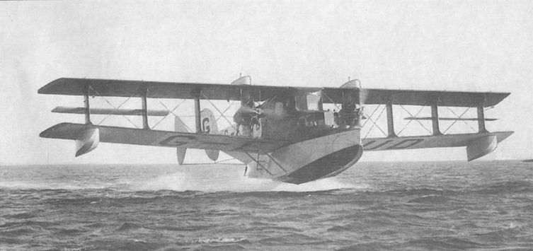
Хотя самолет был спроектирован и построен всего за три месяца, он опоздал к завершению конкурса министерства авиации на коммерческую амфибию, для участия в котором и создавался. Единственный прототип Kittiwake (G-EAUD), оснащенный двумя 200-сильными (149 кВт) радиальными ПД ABC Wasp Mk II, совершил первый полет 19 сентября 1920 года. Из-за отсутствия интереса со стороны потенциальных заказчиков, самолет был пущен на слом в 1921 году.
В 1918 году компания "Vickers Ltd" приобрела долю в "Saunders" и сделала запрос на разработку и постройку прототипа двухмоторной летающей лодки - биплана, позже получившего название Vickers Valentia. Оснащенный двумя 650-сильными (485 кВт) моторами Rolls-Royce Condor IA, самолет был облетан и успешно прошел испытания в 1922 году, но остался в единственном экземпляре.
<...>
Показать полностьюShow all
Flight, September 1920
THE AIR MINISTRY SEAPLANE (AMPHIBIAN) COMPETITION
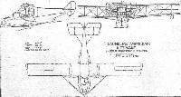
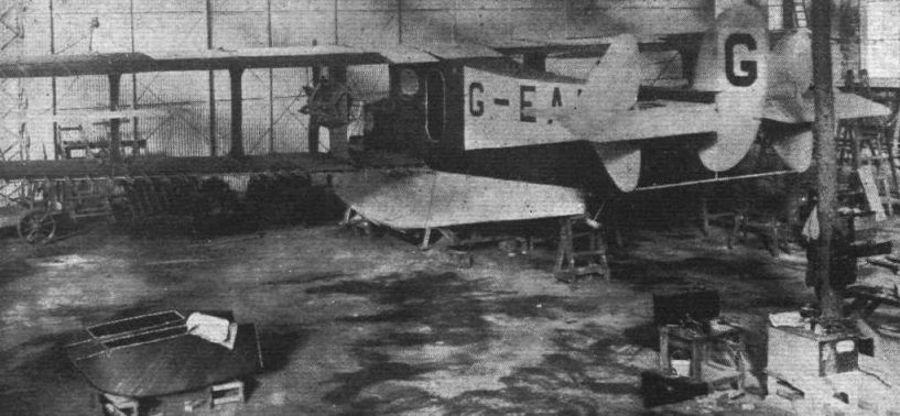
The Saunders "Kittiwake"
In examining the Saunders "Kittiwake" amphibian flying boat designed for the Air Ministry Competition, one is at a loss to decide which one admires most - the originality of the general lay-out, the excellence of the detail work, or the courage of Mr. Saunders in sanctioning the building of a machine which is such a radical departure from orthodox practice. In almost every respect the "Kittiwake" differs from what one has become accustomed to regard as standard practice. This applies not only to the general arrangement, but equally to the majority of constructional details. And when a closer inspection is made it is at once realised that the originality of the design is not due to a desire on the part of the designer to produce "something different from everybody else's," but is the result of a serious attempt to meet the requirements of commercial aviation. Thus the passengers have been placed where they may be assumed to be as safe as possible in an aircraft - well above the water line and well aft of the nose, without any engines or other heavy weights behind and above them. The view obtained is excellent, and the cabin is roomy with plenty of head room.
The question of fire has been carefully considered, and in order to reduce to a minimum any possibility of the cabin catching fire in case of a crash, the tanks have been placed on the top plane, above their respective engines. This not only gets all petrol away from the hull and cabin, but means in addition direct gravity feed to the carburetors from the main tanks, reducing the length of piping to a minimum and doing away with all petrol systems as the term is usually understood.
The Cabins
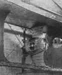
The general arrangement drawings of the "Kittiwake" published herewith will give a good idea of the lay-out and proportions of the machine. Fundamentally, it will be seen the machine is a flying-boat, with a superstructure added which forms the passengers' cabin. This cabin is reached through doors in the side in line with the trailing edge of the bottom plane. For use on the sea short steps are provided on the sides of the boat, so that a small boat will simply run up just behind the trailing edge of the lower plane and the passengers enter by way of the steps and doors. Being aft of the planes the passengers are well away from the airscrews, so that even with the engines running the machine may be boarded without danger to the passengers. Inside the cabin seats are arranged in the form of "settees" along the sides, and six passengers can be very comfortably seated, while it is possible to get in seven without undue crowding. Should it be decided to provide parachutes as a standard equipment of passenger machines, these could be stowed in lockers along the sides of the aft portion of the fuselage, and as the doors in the cabin are just above the trailing edge of the lower plane, the passengers could easily jump clear. From the passengers' cabin steps lead down into the pilot's cabin in front, which is on a slightly lower level so as to provide a forward view for the passengers. The pilot sits on the starboard side and controls the machine by means of the usual controls, while on his left are two wheels for operating the variable camber and the tail trimming respectively.
An ordinary crank handle is also provided for raising and lowering the land under-carriage, the two wheels of which are housed in slots in the boat hull, the water being kept out by spring-loaded doors in the bottom. The engineer is normally housed in the pilot's cabin, and can if necessary walk through the cabin and out on the wings to the engines. For anchor handling a small hatch is provided near the nose of the boat hull, while the pilot's cabin has another hatch in the roof.
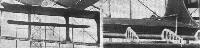
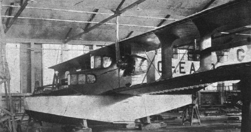
The Boat Hull
Not the least interesting feature of the "Kittiwake" is the general design of the hull, and the manner in which unit construction has been applied to this part of the machine. The hull is of the two stepped type, with the two steps very close together. Aft of the first step the bottom has a slightly more pronounced Vee than that of the front portion, while the Vee aft of the second step is the same as that between the steps.
Behind the steps the bottom remains of Vee formation, although the Vee flattens out somewhat towards the stern of the hull. The latter does not run right out to the stern post, but finishes off about half-way, the tail portion of the body being separate from the boat hull, which is joined to the body along a straight horizontal plane and forms a separate structure. Thus in the case of damage to the boat hull, this can be detached from the main body and a new one substituted, a feature which should be of considerable merit for a commercial machine. The fuselage proper extends back to the tail, and is of similar construction to that of the boat, i.e., a light framework covered with three-ply "Consuta." In the case of the fuselage and sides of the boat hull this Consuta covering is of cedar, while the bottom of the boat is covered with Consuta mahogany.
The fuselage has a slightly concave top aft of the cabin, a feature which one would imagine to tend to cause extra resistance, but according to wind tunnel tests on models of the complete machine, the total resistance is by no means high, and probably the variable camber wings effect such a saving in resistance as to afford considerable latitude in the various items of "parasite" resistance without bringing the total resistance up to a prohibitive figure. Thus the front of the cabin would appear to be very far from giving good streamline form, yet, as we have already said, the total resistance of the machine is certainly not unduly high.
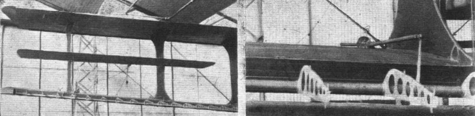
The interesting Main Planes
Mention has already been made of the fact that the wings of the "Kittiwake" are of variable camber. This is not, however, the only interesting feature of the wings. The covering and strutting are also unusual. Instead of the ordinary fabric covering the planes are covered with Consuta cedar, which takes the place of the ordinary internal drag bracing. The leading and trailing portions of the planes, that is to say the portions in front of the front spar and aft of the rear spar respectively are separate structures of duralumin, and are hinged to the spars. The extreme edges are duralumin strips, formed into U, or rather into rounded Vee sections in which the ply-wood covering is free to slide so as to accommodate itself when these portions of the wings are flexed for varying the camber. The ribs of the front and rear portions of the wings are of duralumin and are pivoted by means of a duralumin tube running through the wing and hinged to the spars. At intervals these tubes are provided with cranks, which are in turn operated by means of the cambering gear. This takes the form of a series of longitudinal tubes, attached at their front and aft ends to the cranks on the transverse tubes, and at their inner ends to worms (left and right-hand) engaging with the internally threaded extension of the hub of a small toothed wheel. This wheel, in turn, engages with short racks on the operating rods running through the planes from the controls in the fuselage. Thus when the operating rods are caused, by the wheel in the pilot's cockpit, to slide laterally, they rotate the small toothed wheels, and these in turn cause the worms to travel outwards or inwards, thus flexing the leading and trailing edges up or down. As the overhanging leading edge is shorter than the trailing edge, the pitch on the front worms is greater than that of the rear worms, the gear being so arranged that the chord line of the section is at the same angle of incidence in both positions of the camber.
That the effectiveness of this variable camber, which, by the way, constitutes a patent, is considerable, is evident when it is pointed out that, according to wind tunnel tests on models of the complete machine, one with the camber flat and one with the maximum camber, the maximum speed with two 200 h.p. A.B.C. "Wasp II " engines should be between 105 and 110 m.p.h., while the landing speed is, according to the model tests, about 42 m.p.h. This would give a maximum lift co-efficient of close on 8, which is distinctly good, and in view of the necessarily considerable resistance of fuselage, hull, etc., the drag co-efficient of the wings with flat camber cannot be very great, so that this variable camber arrangement appears to be very well worth while.
The strutting of the wings is also unusual inasmuch as single I struts are employed. These are built-up of vertical and horizontal stringers and formers, covered with Consuta cedar. There is only one set of lift and anti-lift wires, which effects a considerable saving in resistance, and it is thought that this form of construction will be easier to keep aligned, since it does away with incidence wiring. Should, after long wear, the planes have warped to a certain extent, the trim of the machine could probably, be maintained by so setting the cambering gear as to give slightly greater lift on one side than on the other, thus restoring lateral balance. The method of anchoring the wing bracing streamline wires is interesting. There are no wiring plates, the threaded portion of the wires passing through the planes and being anchored there by a simple nut.
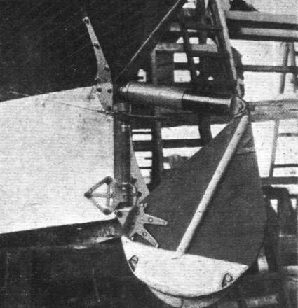
The tail plane is of the monoplane type, although it is braced by a form of triplane structure consisting of transverse stay-tubes with streamline wire bracing. There are two heart-shaped fins, placed some distance out on the tail plane, and a single balanced rudder. As the fuselage stern is well above the water line, and the boat hull extends fairly far aft, there is no need for a tail float, but a combined tail skid and water rudder is hinged to the stern of the boat proper, as shown in one of our photographs.
The Engines
The power plant consists of two A.B.C. "Wasp Mark II" radial engines of approximately 200 h.p. each. They are mounted each on a single I-strut similar to the plain interplane struts, but differing from them in being built up of duralumin instead of wood. The engines are bolted to engine plates of duralumin, the feature which we like least in the whole design. Duralumin is known to become brittle with vibration, and also it should not be exposed to heat. However, if it is found to be unsatisfactory it will be a simple matter to substitute steel plates. The space aft of the engines is covered in by an aluminium cowl, and contains the oil tanks. The petrol tanks, as already mentioned, are mounted on the top plane. Each tank contains 54 gallons, or sufficient for a flight of about 4 hours' duration. This placing of the tanks, while being open to criticism from an aerodynamical point of view, has the great commercial advantage of reducing the risk of fire, while the petrol system becomes extremely simple, the fuel being fed to the carburettors direct from the main tanks by gravity.
Space does not permit of dealing in more detail with the "Kittiwake" this week, but it might be mentioned as something of an achievement that the machine was designed and built in three months. This does not sound very formidable until it is pointed out that the entire drawing office consisted of two men, Mr. F. P. Hyde Beadle the chief designer, and his assistant, Mr. H. W. Gravenell. Among them these two have got out all the working drawings, superintended the construction and - last but not least - have done all their own stress calculations. Those who have had anything to do with designing work will know what this means, and if ever downright hard work and honest endeavour merited success this is surely a case in point. And it is not as if the machine were along orthodox lines. The very novelty of the design necessarily meant coming up against endless snags, and presented a series of problems to be solved, and it may be taken for granted that only by working night and day were they able to do the job in the time at their disposal. It goes without saying that the workmanship is excellent throughout, as befits an old-established boat-building firm of such standing as S. E. Saunders, Ltd., whose boats are world famous. To Mr. S. E. Saunders also every credit is due for his courage in sanctioning the building of a machine so boldly conceived, and whatever is the fate of the "Kittiwake" at Felixstowe, everybody concerned is to be congratulated upon her production and will carry with them all the best wishes for success. To strike out along new lines at a time like the present is a venture which betokens not only farsightedness but also a the roughly sporting spirit, in the best sense of the word.
Показать полностьюShow all

 Wiki
Wiki