Винтокрылы Хафнера
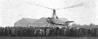
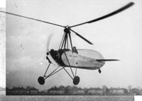
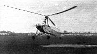
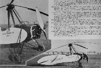
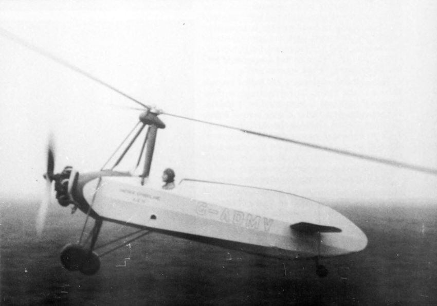
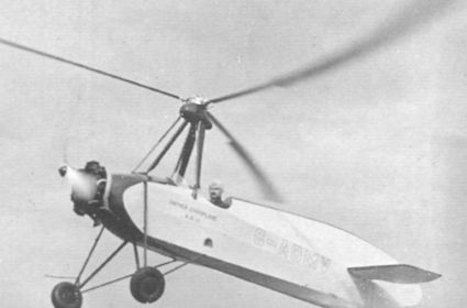
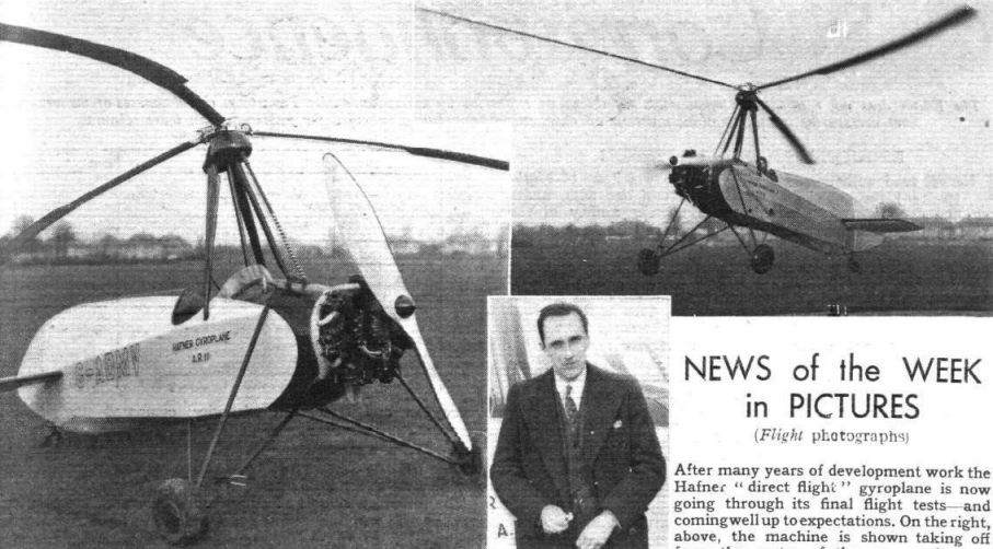
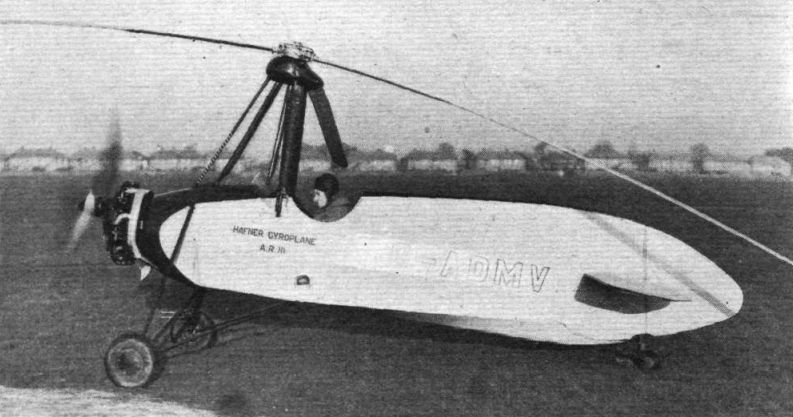
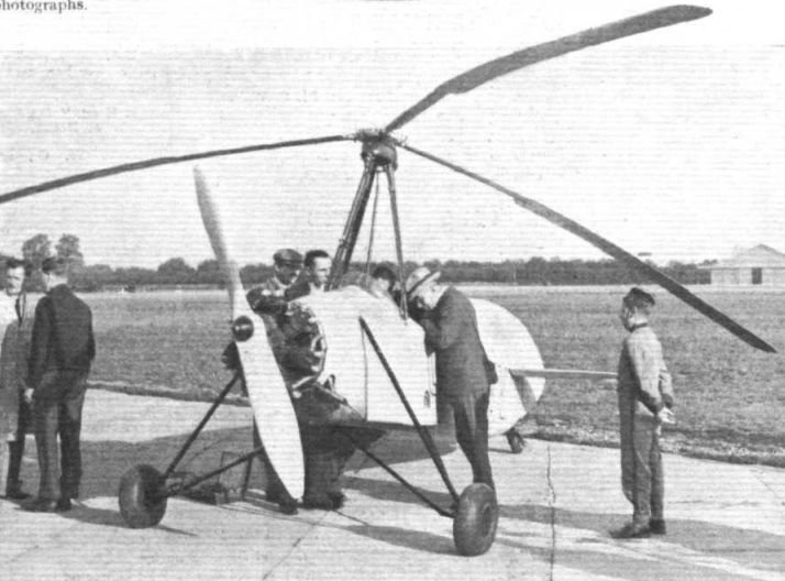
Австриец Рауль Хафнер, финансируемый шотландским "хлопковым" миллионером Дж. Э. Коатсом, в 1928 году приступил к проектированию своего первого вертолета Hafner R.I. Вертолет имел сравнительно короткий фюзеляж и трехлопастный несущий винт большого диаметра (9,14 м), он оснащался силовой установкой с поршневым двигателем ABC Scorpion мощностью 30 л.с. Вскоре после начала испытаний в Вене в 1930 году было выявлено, что гироскопический эффект этого винта слишком велик, поэтому был построен усовершенствованный вариант R.II сходной конфигурации, но с вертикальным оперением большего размера для компенсации реактивного момента несущего винта и облегченным звездообразным поршневым двигателем Salmson мощностью 40 л.с. В 1932 году Рауль Хафнер стал работать в Великобритании, где через два года основал компанию "AR.III Construction (Hafner Gyroplane) Company" и занялся созданием нового автожира, сходного по концепции с продукцией "Cierva Autogiros". Был построен всего один экземпляр, который успешно летал в 1937-1938 годах. Он получил обозначение AR.III Gyroplane и имел трехлопастный авторотационный винт, установленный над фюзеляжем на пилоне с подкосами. В носовой части фюзеляжа был установлен звездообразный двигатель Pobjoy Niagara, вращавший двухлопастный тянущий винт; кроме того, автожир имел неубирающееся шасси с хвостовым колесом и место на одного человека. Задняя часть фюзеляжа включала в себя длинный надфюзеляжный киль, сужавшийся до толщины руля направления и создававший большую площадь вертикальной поверхности. Отличительной особенностью конструкции автожира стала система контроля несущего винта компании "Gyroplane", обеспечивавшая контроль как циклического, так и общего шага лопастей и ставшая стандартной для динамической системы вертолетов.
Рассматривались планы постройки двух- и трехместных автожиров, получивших обозначения AR.IV и AR.V, но, несмотря на то, что постройка данных машин была начата, разразившаяся Вторая мировая война заставила прекратить работы по ним.
<...>
ТАКТИКО-ТЕХНИЧЕСКИЕ ХАРАКТЕРИСТИКИ
Hafner AR.III Gyroplane
Тип: одноместный автожир
Силовая установка: один звездообразный ПД Pobjoy Niagara мощностью 90 л. с. (67 кВт)
Летные характеристики: максимальная скорость на уровне моря 193 км/ч; крейсерская скорость на оптимальной высоте 177 км/ч
Масса: пустого 290 кг; максимальная взлетная 408 кг
Размеры: высота фюзеляжа 5,44 м; диаметр несущего винта 10,00 м; площадь, ометаемая несущим винтом, 78,54 м2
Показать полностьюShow all
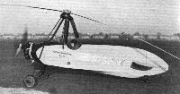
Flight, September 1935
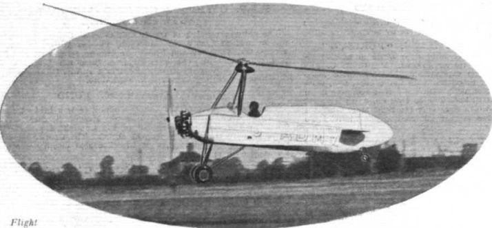
The A.R.III gyroplane, built by the A.R.III Construction Company at the Martin-Baker Aircraft Works at Denham. A novel form of blade attachment obviates any difficulties due to loads building up on hinges and makes control of the machine particularly light. The variable incidence mechanism by which the machine is controlled about all axes without necessitating the use of a method of tilting the rotor head is effective and simple and has already been proved in flying tests.
It is expected that vertical take-offs will be possible by using the kinetic energy of the blade mass when it is speeded up, before the start, faster than is needed for level flight. A Pobjoy R. engine of 90 h.p. is being used.
Показать полностьюShow all
Flight, February 1937
A NEW ROTOR CONTROL
First Details of the Hafner Gyroplane: "Finger-light" Control: Improved Rotor Efficiency
THEORETICALLY it should be possible to suspend the blades of a rotating-wing aircraft on wires, provided that the blades were stable in pitch, and if some means could be found of getting the blades started on their circular path. It is rather the stone-on-a-string problem in a slightly different form, or perhaps one would be nearer the mark in comparing it with the cowboy's "building a loop" in his rope. In the type of rotor head on which he has been working for several years Mr. R. Hafner has made use of this principle, and the very light rotor control of the A.R.III gyroplane is a direct result of suspending the blades on tension members of small diameter which can twist under relatively small torsional loads. In this way friction is greatly reduced and the pilot's controls become as light as those of a fixed-wing aircraft.
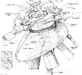
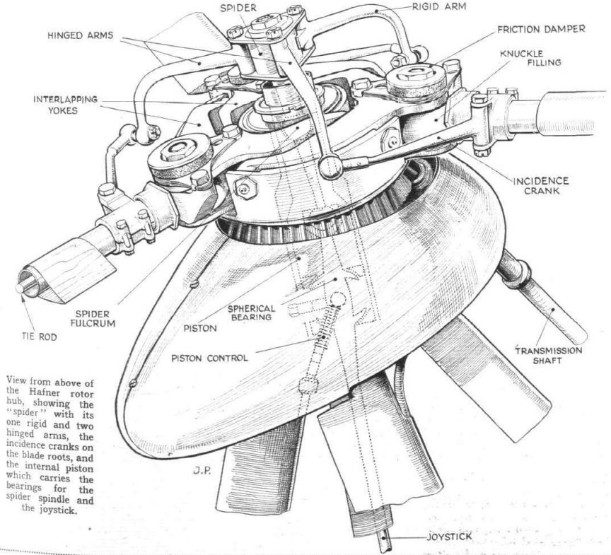
The torsionally elastic suspension of the blades is by no means the only interesting feature of the Hafner rotor, but it does form the basis for the rest of the mechanism, which is shown in the sketches which illustrate these notes.
Before describing the mechanical details it may be of assistance if the fundamental principles are explained briefly. The rotor blades are attached to the head in the orthodox manner, with horizontal hinges which permit the blades to "flap," and vertical hinges with friction dampers for permitting the blades that slight freedom to alter their spacing to which one has become accustomed. The actual attachment of the blades to their hinged forks is, however, by way of the "wire" referred to above, so that in addition to the freedom provided by the two sets of hinges the blades have a third degree of freedom, i.e., to alter their pitch angle. The last-mentioned freedom is, however restricted or damped, as will be explained later.
The inner end of each blade carries a crank arm on a vertical hinge, the hinge being incorporated in order to leave the blades free to "catch up" or lag behind one another. A so-called ''spider'' is mounted centrally above the rotor head, and also carries three arms mounted on vertical hinges. The free ends of the blade cranks are connected (by a cup and ball joint) to the free ends of the spider cranks. When the spider is raised, by means of a separate control in the cockpit, its three crank arms rise with it and carry with them the free ends of the blade cranks, thereby increasing the pitch angles of all three blades (the spider rotates with the rotor head, of course), and when the spider is lowered the pitch angles are reduced. This control might be termed the lift control, as it varies the amount of lift given by the blades, and is used for steep take-off and for checking sinking when landing.
The flying control has the effect of shifting the centre of lift of the whole rotor system by causing the blades to assume an increased pitch angle at one point of their travel around the circle and a decreased pitch angle at other points. This is effected quite simply by tilting the spider. Obviously, if the spider is tilted back the blades will assume a low-pitch angle when passing through their rearmost position and a larger-pitch angle when passing through the foremost position, thus shifting the centre of lift ahead of the rotor pivot and thereby causing the machine to climb. If the spider is tilted to the left the pitch angle will be large on the right-hand side and small on the left-hand side, and the machine will bank and turn to the left.
Flying controls on the A.R.III gyroplane also include a trimming tailplane and a pedal-operated rudder of orthodox type.
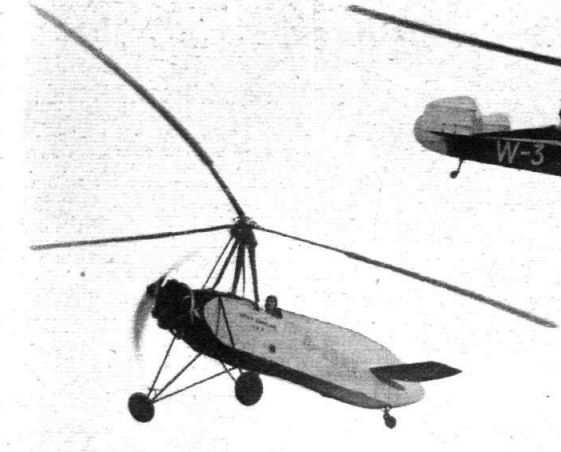
Details of the actual mechanical application of the fundamental principles outlined above are illustrated in the sketches. The rotor blades have single steel-tube spars of small diameter but heavy gauge. No attempt has been made at saving weight on the rotor blades; in fact, weight has deliberately been kept fairly high in order to obtain a good flywheel effect to assist take-off and to ease the machine down gently through the last couple of feet of the landing. In this connection it may be pointed out that the mass of the blade per unit of frontal area is important. In the A.R.III, Mark II, which is the machine now flying at Hanworth, this value reaches a high figure and has much to do with the good energy-assisted take-off and the shockless landing without preliminary glide which are features of this machine.
At its outer end the blade spar has screwed into it a steel plug used for balancing purposes. The rotor blades are of aerofoil section over the outer two-thirds only, the inner third of their length being of plain streamline section. The main blade spar terminates at its inner end approximately at the point where the streamline and aerofoil sections merge into one another. From this point to the vertical rocking hinge fitting on the rotor head the centrifugal pull of the blade is normally taken not by a continuation of the tubular spar but by a steel tie-rod of relatively small diameter. This is, in fact, the "wire" of our theoretical blade suspension. At its outer end this tie-rod is screwed left-hand into the outer spar tube, and at its inner end it is screwed right-hand into the knuckle root fitting.
Precautionary Measures
The main blade spar does have a tubular inward extension, but normally this does not carry the centrifugal loads. The tube has a shoulder at its inner end, and the length of the tie-rod is so adjusted that normally the shoulder is just clear of a collar attached to the knuckle fitting. Should, however, the tie-rod stretch (through, for instance, over-revving of the rotor), or should it break, the shoulder of the tubular spar root will bear on the collar, and the blade will be secured against centrifugal pull. The friction will, however, be so great that the blade incidence will be locked, and the pilot will at once know that something has happened, as the rotor will become "rough" and his incidence control will be inoperative. That does not mean that he has lost all control, but merely that the machine will have to be controlled by the normal flying controls, viz., rudder and elevator; lateral control will, of course, be lacking, but it should be possible to land the machine without doing very serious damage. In any case, there is little likelihood of a tie-rod breaking, as its load factor both in tension and torsion is high. Fatigue might be feared, but experiments have shown that in view of the length of the rod and the small amount of twist to which it is subjected, there is little reason to fear trouble from this source. The spar root tube, it will be realised, serves to carry the blade in bending when the rotor is stationary, its inner end making a bearing but not a tension anchorage.
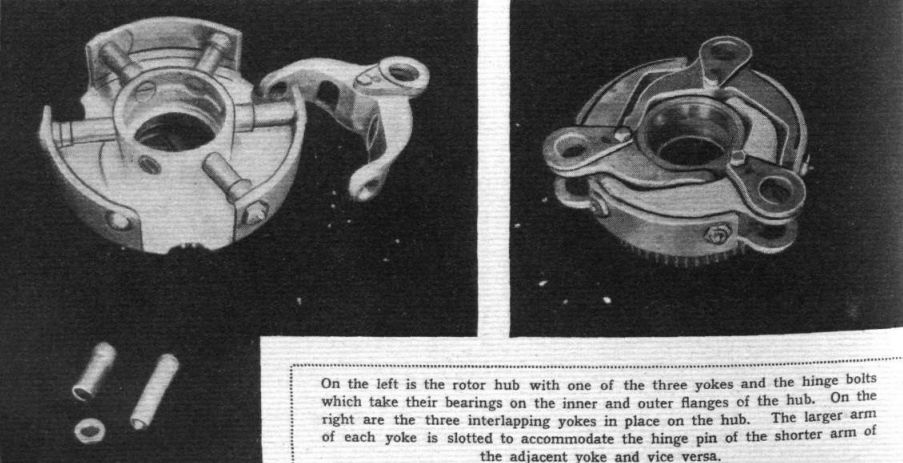
The rest of the Hafner rotor head mechanism is fairly straightforward. The hub is a partly conical bowl with an internal cylinder which carries the taper roller bearings by which it is attached to the rotor spindle. A fork or yoke forms the attachment of the blade root to the rotor hub. The three yokes are identical but unsymmetrical, the longer arm of each taking its bearing on the outer wall of the cone and its inner on the internal cylinder. The hinge pins are so arranged that their axes intersect the rotor axis and so avoid any couples about the centre of the hub, such as might arise due to unequal lifts of the blades in flight.
Pitch Adjustment
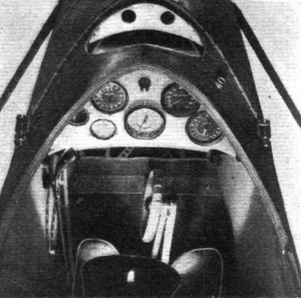
The spider which carries the three crank arms used for varying the incidence simultaneously on all three blades is carried on a spindle mounted in a piston which can slide up and down inside the rotor axle. The spider, of course, turns with the rotor head, but the piston is prevented from rotating, as is also the extension of the spider spindle which terminates in the joystick. A double-jointed arrangement is incorporated in order to provide the usual aircraft type of control, i.e., pull-for-climb, push-for-dive. The piston is moved up and down by means of a Simmonds-Corsey control, the operating lever of which is placed on the left-hand inside of the cockpit, its neutral and forward positions being locked by a pawl and teeth on a quadrant. The rearmost part of the quadrant is without teeth in order to compel the pilot to hold the lever back. This is done because this setting which corresponds to maximum pitch angle, is used for landing only and for the initial part of energy-assisted take-offs. As soon as the pilot releases this lever it moves forward automatically until the pawl engages with the quadrant tooth which corresponds to normal pitch angle.
The drive for starting the rotor includes a clutch and gear box unit, and there is, of course, a freewheel arrangement. The drive is interesting and has had a good deal of development work done on it, but, unfortunately, space does not permit of describing it in detail. It incorporates such refinements as a synchromesh device, and great trouble has been taken to protect the rotor head and blades against shock loads during the revving-up process. That this is necessary will be realised when it is pointed out that each of the three rotor blades weighs about 35 lb., and that the rotor is speeded up to some 240 r.p.m. for energy-assisted take-offs.
Steep Angle of Climb
A recent demonstration at Hanworth showed the Hafner gyroplane to leave the ground with a run of about two yards, the subsequent climb being very steep. Actual measurements are not available, but it is estimated that the A.R.III, Mark II. should be able to clear the standard 66ft. "screen" after a run from a standing start of about sixty yards. Actual official performance figures have not yet been established, but it is expected that the top speed should be about 125-128 m.p.h. and the cruising speed approximately 115 m.p.h. Owing to the amount of energy which can be stored in the rotor, landings can be made straight off the "sink-approach" with preliminary glide.
At an all-up weight of 890 lb. the machine carries 70 lb. of petrol and oil and 180 lb. of pilot and luggage. The duration is 1 1/2 hours, or 170 miles in still air. The diameter of the rotor is 32ft. 10in. and the rotor disc area is 846 sq. ft. As each blade has an area of 6.68ft., the "solidity" is 2.37 per cent. The loading per sq. ft. of rotor blade area is 43.6 lb.
The A.R.III, Mark II, is regarded by the makers, A.R.III Construction, of 42a, Walmer Road, London, W.10, as a flying test bench rather than as a production type. Mr. Hafner, who has been responsible for all the technical research in this country throughout the development period, the partnership between him and Mr. Nagler having been dissolved some years ago, intends to use the machine for exhaustive flying trials so as to discover if there are any mechanical "snags" left in the mechanism, having already satisfied himself that the Hafner system of control is fundamentally sound.
Показать полностьюShow all

 Wiki
Wiki