Gloster Grouse
В 1923 году авиаконструктор Генри Фолланд разработал новый тип бипланной коробки для истребителей, которая совмещала в себе достоинства крыльев биплана и моноплана и получила обозначение Gloster H.L.B. Section, после чего компания решила в инициативном порядке переоборудовать для ее отработки опытный самолет Mars III/Sparrowhawk II. В бипланной коробке нового типа нижнее крыло имело угол установки меньше, чем у верхнего крыла. На взлете подъемную силу развивали оба крыла, но в полете нижнее крыло подъемной силы практически не создавало, имея также небольшое аэродинамическое сопротивление. Таким образом, биплан как бы "виртуально" превращался в моноплан. Переоборудованный самолет получил новое обозначение Gloster Grouse Mk I; во время первых испытательных полетов передняя кабина машины была выполнена закрытой. Испытания самолета были признаны успешными, однако разработчик все же решил построить более совершенный вариант самолета - им стал Gloster Grebe. Сам же Grouse в 1924 году был вновь модифицирован - на него установили новый двигатель, звездообразный Armstrong Siddeley Lynx II мощностью 180 л. с. (134 кВт), после чего машина использовалась в качестве прототипа двухместного учебно-тренировочного самолета, предложенного компанией командованию британских ВВС. Однако новая машина, получившая обозначение Grouse Mk II, интереса у британского Министерства авиации не вызвала, после чего была предложена на экспорт. Прототип для оценки приобрела авиаслужба Королевской Армии Швеции, однако дальнейшие планы по закупке небольшой партии серийных машин были отменены.
ТАКТИКО-ТЕХНИЧЕСКИЕ ХАРАКТЕРИСТИКИ
Gloster Grouse Mk I
Тип: опытный биплан
Силовая установка: один 9-цилиндровый ротативный ПД Bentley B.R.2 мощностью 230 л. с. (172 кВт)
Летные характеристики: макс. скорость на уровне моря 206 км/ч; практический потолок 5790 м; продолжительность полета 3 ч 45 мин
Масса: пустого 624 кг; максимальная взлетная 962 кг
Размеры: размах крыла 8,23 м; длина 5,79 м; высота 3,07 м; площадь крыльев 19,04 м2
Показать полностьюShow all
Flight, July 1923
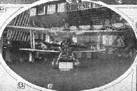
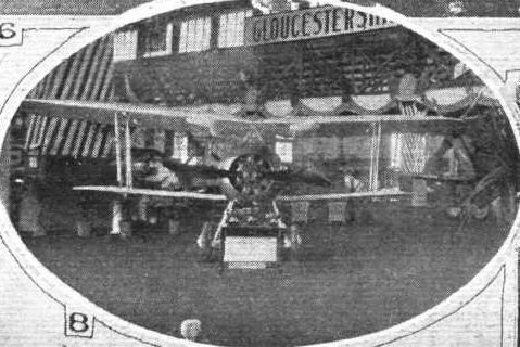
Gothenburg International Aero Exhibition 1923
THE MACHINES
Gloucestershire Aircraft Company, Ltd., Cheltenham
THE Gloucestershire Aircraft Company, the constructors of the world-famous "Mars I," or "Bamel" racing machine, which holds the British speed record of 196-6 m.p.h., have two types of machines at Gothenburg, one on view in the exhibition itself, and the other giving actual flying demonstrations. Both machines are of recent design, for which Mr. H. P. Folland, who also designed the "Mars I," is responsible, and, as may be expected, possess several distinctive features.
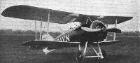
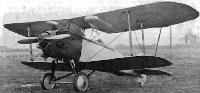
The first of these machines - that which is being shown in the exhibition - is known as the Gloucestershire "Grouse," and has been designed with the object of serving the purpose of an intermediate type of scout for training work, or it can equally be employed as a ship's 'plane for duties with the fleet.
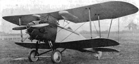
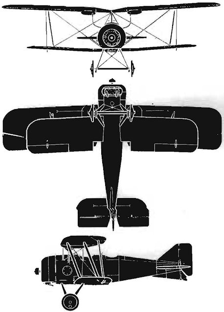
As will be seen from one of the accompanying illustrations, it is a single-seater tractor biplane, with a comparatively deep and well streamlined fuselage. The special feature of the "Grouse" is in the improved arrangement of the wings, which have high lift and medium lift sections. The top plane, it will be observed, is very much larger in comparison with, the lower plane, both as regards span and chord. It is stated that in actual tests these wings have proved to be superior to the more orthodox arrangement usually employed on machines of this type, in that a lower landing speed, greater load-carrying capacity, and a better performance at the height of operation required for a scout, are obtained. The controllability, stability and general handling of the machine is also greatly improved.
The top planes are in two sections, and are attached to a pylon of two inverted V's of steel tubing, while the lower planes, also in two sections, are attached to short wing roots on the lower longerons of the fuselage. There are one pair of interplane struts each side, and the ailerons, which are fitted to both upper and lower planes, are connected by struts.
Another interesting feature is the petrol system, which is direct gravity feed, and is of such simple nature as to be quite fool proof. Reference to the illustration will show how the two large petrol tanks are located on the top plane – well away from the fuselage.
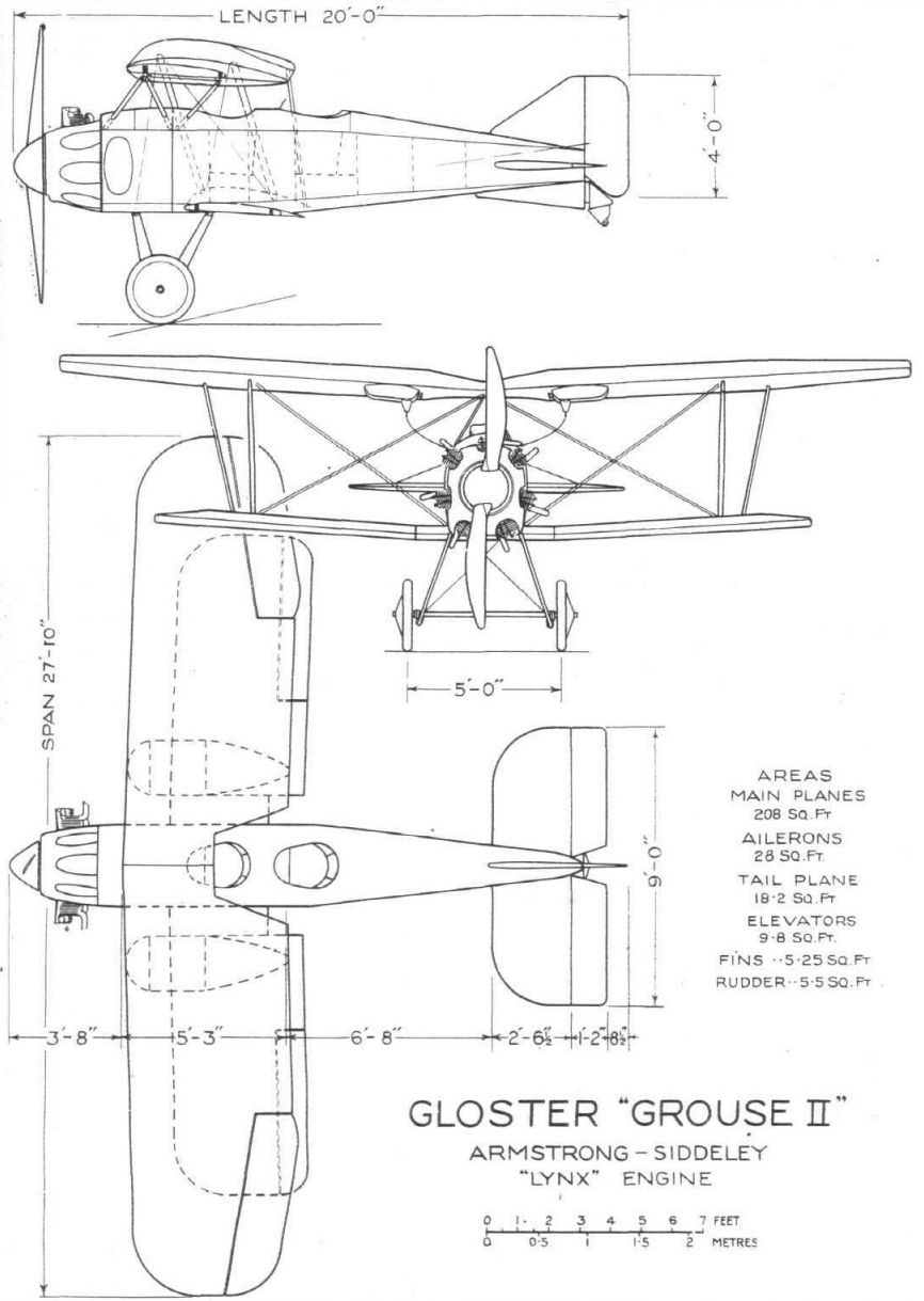
The general dimensions of the "Grouse" are :- Span, 27 ft. 6 ins.; overall length, 19 ft.; height, 9 ft. The engine fitted in this machine is a 230 h.p. B.R.2, rotary, air-cooled.
<...>
Показать полностьюShow all
Flight, November 1925
TWO "GLOSTER" MACHINES
The "Grouse II" and the "Grebe II"
UNTIL recently it has not been possible to describe in detail one of the most successful machines turned out by the Gloucestershire Aircraft Company, i.e., the famous "Grebe." This machine has now been supplied in very large numbers to squadrons of the Royal Air Force and, in accordance with the Air Ministry's regular procedure, when a type has been put into quantity production, it is usually given free as regards publication of detailed descriptions. At the outset it should be pointed out that the Gloucestershire Aircraft Company is now also in a position to supply the "Grebe" to any foreign Government contemplating the purchase of British aircraft.
The "Grebe" is, as already mentioned, one of the most successful service machines ever produced by the Gloucestershire Company, and its qualities are, of course, well known in this country. By way of illustrating the remarkable quality of the design and workmanship of the "Grebe," we may call attention to a test recently made, and about which, so far, little has become known. In the United States it has been the custom for some time for test pilots deliberately to attempt to break their machines in the air by diving them at very high speed and then flattening out suddenly. This has been possible in America because American pilots are equipped with parachutes. In this country, however, it has not been customary to fit parachutes as a standard part of the equipment, and it was not until recently that, the Air Ministry having placed an order in America for parachutes, it has become possible for British pilots to earn-out this kind of test. Some time ago, however, we are informed, one of the Gloucestershire "Grebes" was tested in this manner by one of the Martlesham pilots. Taking the "Grebe" up to a great altitude, the pilot put his machine into a long, steep dive and, when a speed of something like 240 m.p.h. had been reached, he flattened out suddenly and "zoomed," expecting the wings to break, and being ready to leave the machine in his parachute. Quite contrary to all expectations, the "Grebe" did not break its wings, and a perfectly normal landing was subsequently made. On careful examination afterwards, it was found that nothing had broken in the machine structure, and the only adjustment requiring to be made to put the machine into flying trim again was the tightening up of some of the bracing wires which, not unnaturally, had stretched under the terrific loads imposed. The test is not only an eloquent piece of testimony to the excellence of the design and construction of the Gloster "Grebe," but also to the courage of the pilot. It will readily be realized that for the pilot deliberately to do something which his knowledge and all his instincts tell him to be wrong, requires remarkable courage and a vast amount of will power.
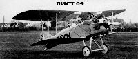
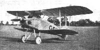
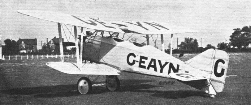
Although the Gloucestershire Aircraft Company is prepared to supply the "Grebe" type in any quantity, it is pointed out that a very unique combination is available in the Gloster "Grouse II," and "Grebe II." The former is a two-seater training machine, quite remarkably easy to fly, and yet capable of all kinds of evolutions in the air, while the latter is, of course, a single-seater fighter equipped with all modern instruments, armament, etc. The reason why the two types, taken together, form such an excellent combination is, firstly, that both in aerodynamic and structural design the two types are very nearly identical, and that the majority of fittings, etc., are interchangeable. This applies particularly to the fuselage fittings, tail skid, wing fittings, etc., so that where both types are used, the number of spares can be reduced to a minimum, which, of course, makes for cheapness.
Furthermore the "Grouse II," is fitted with the Armstrong-Siddeley "Lynx" engine, while the "Grebe II" has an Armstrong-Siddeley "Jaguar" engine. It is, of course, well-known that the great majority of parts are identical in these two engines, so that the same saving in spares applies to the engines, i.e., the "Jaguar" is, practically speaking, a double "Lynx," the cylinders, pistons, etc., being identical in the two types, so that again the number of spares that has to be stocked can be cut down to a minimum, as the great majority of spare parts can be used for replacing damaged or worn-out parts in either engine. There is, therefore, a great deal of inducement for those contemplating purchasing aerial equipment in Great Britain to give the two Gloster types very careful consideration, since coupled with the excellent flying qualities of both types, there is this further advantage of a reduction of spares.
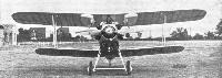
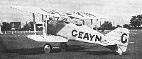
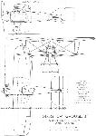
As the two Gloster machines are so very similar, the following descriptive article may be taken, except where otherwise stated, to apply to both. The photographs and scale drawings published this week illustrate the "Grouse II," and photographs and scale drawings of the "Grebe II" will be published in our next issue.
The two Gloster biplanes under review in the present article are of somewhat unusual aerodynamic design in that the top plane is of much larger area than the bottom plane, but is of different wing section. Neither section is quite identical with any section of which particulars have been published, but it may be said that the section of the top plane resembles that known as airscrew 4, while the bottom plane is very similar to airscrew 2. This means of course that, whereas the bottom plane is of the type known as a "thin" section, the top plane is a thick or high-lift section.
There seems to be reason to suppose that the excellent flying qualities of the two machines are due in a great measure to this particular aerofoil arrangement. Air. H. P. Folland, who is chief engineer and designer of the Gloucestershire Aircraft Co., has employed this combination further to gain somewhat in efficiency, by staggering the two wings in relation to one another and by placing the top plane at a slightly larger angle of incidence than the bottom plane. The result of this arrangement is that a certain amount of fore and aft stability is provided so that the tail of the machine can be kept fairly small. It seems probable that at top speed the upper wing is carrying nearly the whole load, and by suitable design of the difference in angle of incidence and stagger, it is possible so to arrange matters that in that case the top plane is flying at a point of its curve where drag is small, while the bottom plane, being a thin aerofoil, will also, of course, have a very small drag, with the result that the machine approaches monoplane efficiency much more closely than is possible with a biplane arrangement in which the two wings are of the same area and of the same wing section. In other respects the two Gloster machines are of orthodox design but they show very clean lines, in which the Gloucestershire Aircraft Co.'s racing experience has been made use of in so far as it is applicable to service types of machines. The Armstrong-Siddeley engine is neatly cowled-in, and the streamlined shape is further retained by the special type of propeller boss which has for several years been a feature of the Gloster machines. In this type of propeller the metal spinner usually found is absent and its place is taken by a wooden spinner or enlarged boss built of wood and integral with the propeller itself, from the laminations of whose blades it is made.
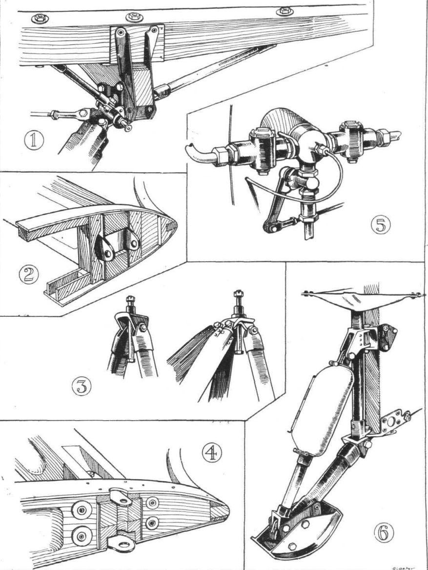
Another feature of the two Gloster machines, which is not, however, peculiar to these but is incorporated in the majority of modern British service machines, is the placing of the petrol tanks in the top plane where fire risk is small, and where, moreover, direct gravity feed to the engine can be provided. In this connection it should be pointed out that our photographs of the "Grouse II," published herewith, show the older type of tank, whilst the general arrangement drawings might in this respect be regarded as a compromise in that in the front elevation the new type of tank is shown while the dotted lines in the plan view represent the outline of the older tanks. The type of tank shown in the front elevation is fitted as standard in the latest machines. This type of tank is almost entirely buried inside the wing and therefore offers considerably less head resistance than did the older type shown in the photographs. A further difference which should be pointed out relates to the ailerons of the top plane. In the photographs these have their trailing edges in continuation of the trailing edge of the main plane, but in the latest type the aileron projects slightly, as shown in the plan view of the general arrangement drawings.
The aileron control of the Gloster machines is somewhat unusual in that only the lower ailerons are operated direct, the movement of these being transmitted to the top plane flaps by a single strut on each side. No cables passing over pulleys are employed in the aileron control, tie rods running to a "T" crank being used in the lower plane from which cranks the tie rods run direct to the controls, short lengths of cable being used where the controls pass through fibre blocks into the fuselage. The arrangement of the "T" cranks is such that the ailerons are given a differential movement, and doubtless this feature has a good deal to do with the excellent manoeuvrability and the general easy handling of the machine.
Before leaving the subject of the aerodynamic design of these two Gloster machines, it should be pointed out that in the top plane the master section is employed for part of the span only, as the wing is thinned down towards the tips and also at the ends towards the attachment to the centre section struts, or rather to the struts of the cabane, as no top centre section, in the ordinary sense of the term, is employed. By thinning down the wing in the centre the view from the cockpit is considerably improved and in the case of the "Grouse II," access to the front cockpit is somewhat facilitated.
TWO "GLOSTER" MACHINES
The "Grouse II" and the "Grebe II"
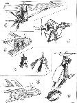
LAST week we illustrated the Gloucestershire Aircraft Company’s two-seater training machine, type "Grouse II," and described the aerodynamic design of the machine, as well as that of its "big brother" the "Grebe II." It was pointed out that generally speaking the two machines are very similar, and that the detail description, except where otherwise stated, could be taken to apply to both types. In the present issue of FLIGHT we publish photographs and general arrangement drawings of the "Grebe II," and a number of sketches showing constructional details. The following article deals with the constructional features of both machines, and concludes with a brief summary of the main characteristics, performance figures, etc., of the "Grouse II" and "Grebe II."
<...>
Characteristics of the "Grouse II"
The main dimensions, areas, &c, of the "Grouse II" were shown on the general arrangement drawings published last week, and it is, therefore, unnecessary to repeat them here. The engine fitted as standard is the Armstrong-Siddeley "Lynx" of 180 h.p. at 1,620 r.p.m. The petrol tanks have a capacity of 20 gallons each, while the oil tank, situated in top fairing of fuselage near the engine, has a capacity of 3 1/2 gallons. With the amount of fuel stated the duration is 3 3/4 hours at 10,000 ft.
The load factors of the "Grouse II" are as follows: Front wing truss, 7; rear wing truss, 5; working to a stress of 5,000 lbs./sq. in. for spruce members. The fuselage factors are 5 on front and rear portions for landing loads, and the load factor of the undercarriage is 4 1/2. The weight of the machine fully loaded (with a weight of 360 lbs. for pilot and passenger) is 2,120 lb., giving a wing loading of 10-2 lb./sq. ft., and the power loading is 11-8 lb./h.p. With this loading, the performances of the Gloster "Grouse II" is: Maximum speed, 118 m.p.h.; landing speed, 52 m.p.h.; climb to 10,000 ft. in 17 minutes.; ceiling, 18,000 ft.; duration, 3 3/4 hours at 10,000 ft.
Показать полностьюShow all


 Wiki
Wiki