General Aviation FLB и PJ
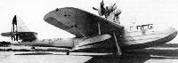
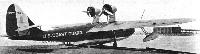
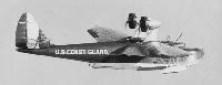
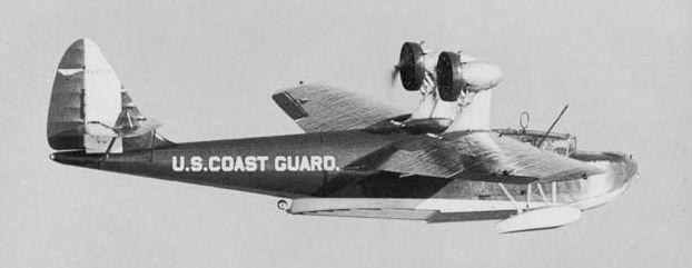
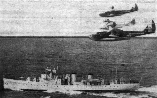
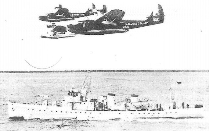
В 1931 году компания "General Aviation Corporation" из Дандолка, штат Мэриленд, построила пять патрульных океанских поисково-спасательных летающих лодок для Береговой охраны США. Гидропланы были разработаны компанией "Fokker Aircraft Corporation of America" под обозначением AF-15, но к тому моменту, как заказчик остановил на них свой выбор, американский "Fokker" стал отделением компании "General Aviation". AF-15 - высокоплан смешанной конструкции с крылом консольного типа имел двухреданный корпус (лодку) и хвостовое оперение с подкосами. К крылу крепятся стабилизирующие поплавки. Силовая установка включает два смонтированных над крылом звездообразных мотора Pratt & Whitney Wasp с толкающими винтами. Экипаж состоит из четырех человек: два летчика, штурман и радист. Самолет начал эксплуатироваться в начале 1932 года, не имея военного обозначения, но потом ему присвоили обозначение FLB (Flying Life-Boat), а позже - PJ-1. Первый из этих самолетов переоборудовали силовой установкой с тянущими винтами, обозначение изменили на PJ-2.
ТАКТИКО-ТЕХНИЧЕСКИЕ ХАРАКТЕРИСТИКИ
General Aviation AF-15 (PJ-1)
Тип: патрульная/поисково-спасательная летающая лодка
Силовая установка: два 9-цилиндровых звездообразных ПД Pratt & Whitney Wasp мощностью по 420 л. с (313 кВт)
Летные характеристики: точно не известны
Масса: пустого 3175 кг; максимальная взлетная 5080 кг
Размеры: размах крыла 22,61 м; длина 16,99 м; высота 4,72 м; площадь крыла 70,05 м!
Показать полностьюShow all
Flight, August 1933
FOR COAST GUARD SERVICE
An American Flying Lifeboat
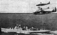
FOR something over a year the American Coast Guard Service has been in possession of some machines specially designed for coast guard work, and during that period they have proved their value on more than one occasion. The conditions for which these machines were designed were extremely severe, and as it is not without the bounds of possibility that some day Britain's coasts may be similarly equipped, we have thought that a description of this interesting American production might be welcomed by our readers. When the day comes for the National Life Boat Institution to "take to the air," we sincerely hope that Lord Mottistone, who will be more familiar to our readers as Gen. Seely, will be on board the first machine.
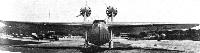
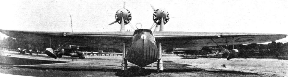
In designing the American "Flying Life Boat," the engineers of the General Aviation Manufacturing Corporation of Dundalk, Maryland, were faced with rather unusual problems. The co-operation of the engineers of the U.S. Coast Guard Service was, of course, available, and between producers and operators the type FLB-51 was evolved. Taking off from and alighting on rough water was a first consideration. Apart from the question of hull shape, this meant protecting the airscrews from spray. Consequently the monoplane type of wing structure was chosen, with two Pratt & Whitney "Wasp" engines mounted above the wing and arranged to drive pusher airscrews. This gave a position in which it is almost impossible for spray to find its way past the trailing edge of the wing on to the propellers, unless the machine "takes it over green."
A second desideratum was ability always to return to its base, and the machine therefore had to be so designed that it would fly comfortably with one engine stopped. This led to the adoption of two Pratt & Whitney "Wasps" for the necessary power reserve, and to the placing close together of the two engine nacelles, so that with one engine stopped the centre of thrust should not be too far removed from the centre of resistance, and the machine actually is said to require very little rudder to maintain its course with one engine out of action.
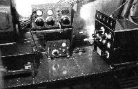
Yet a third necessity in the planning of the "Flying Life Boat" was that it should under all conditions be in wireless communication not only with its base for giving reports, but with shipping which might be sending out S.O.S. messages, or hastening to the aid of a vessel in distress. Thus the radio equipment on the FLB-51 is unusually powerful and complete.
If the operational requirements were severe, the structural problems were no less so. It was not desired to employ a greater number of structural materials than strictly necessary, but at the same time, the buffeting to which a machine of this sort might be subjected demanded the greatest possible strength. As in all other branches of engineering, a compromise had to be made, and this took the form of using Duralumin and "Alclad" for the hull and wing-tip floats, wood for the wing, and welded-steel tube construction for the tail surfaces and engine nacelle supports.
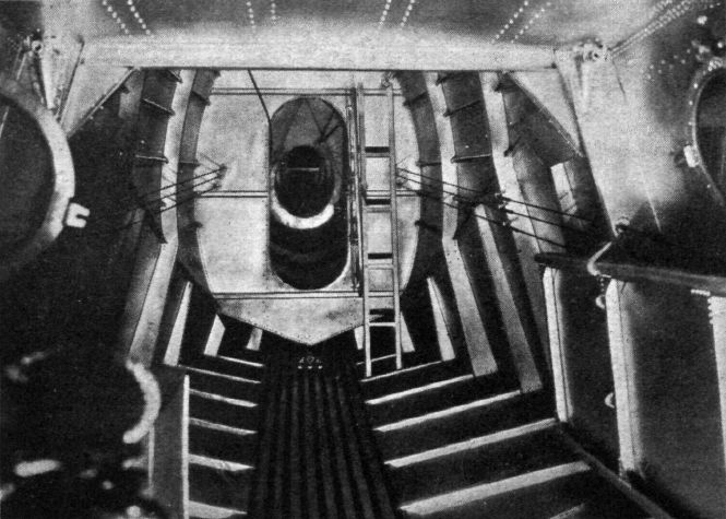
The Hull. - The design of the hull of the Antares differs from British practice in that the portion from the rear step to the stern is a fairly light monocoque metal structure whose function is mainly to carry the tail, but not to do much work hydrostatically or hydrodynamically. The forward portion, on the other hand, is of very sturdy construction, with watertight bulkheads dividing it into compartments so that damage to any one spot will not flood the entire hull. The reserve buoyancy is large, in the neighbourhood of 400 per cent., so that even after extensive damage the machine should keep afloat. To protect the hull against corrosion, all aluminium and duralumin parts are first anodically treated. They are then primed with red oxide and given two or three coats of pigmented varnish. The “Alclad” skin plates have bitumastically treated fabric strips interposed between the plate joints to ensure water tightness.
The Wing. - Basically the monoplane wing is a cantilever structure, of wood construction, with two main spars to take the bending loads, and a laminated skin designed to resist torsion and the shear which is imposed by the drag forces. Spruce, birch and ash are the woods used.
Power Plant Installation. – The engine nacelles, of welded chrome molybdenum steel construction, are designed to take engines from 400 to 600 b.h.p. The oil tanks are housed in the bulbous noses of the nacelles, and adjustable louvres are provided in order to control the oil temperature. The petrol tanks, of which there are four, are built into the wing, each having a capacity of 110 American gallons. The fuel system includes hand priming for the petrol pumps, and the pipes to the priming system are the only fuel pipes taken through the interior of the hull, so that fire risk is very small.
Accommodation and Equipment
The hull is divided by three watertight bulkheads into four compartments. In the extreme bows of the hull is a small compartment used mainly for stowing mooring gear, etc. Its opening is normally closed by a hatch cover.
Behind the mooring compartment comes the pilots' cockpit, with seats placed side by side with a gangway between them. The instrument boards are individually and indirectly lighted, and all the engine instruments are of electric type. The navigational equipment is very complete in view of the function of the machine, and the compass is supplemented by a directional gyro and an artificial horizon.
Aft of the pilots' compartment comes the cabin for the navigator and wireless operator. Tables are provided to enable these two members of the crew to work in the greatest possible comfort, and the wireless equipment itself is very complete. The electric current is obtained from an engine-driven generator charging a 65-ampere-hour 12-volt accumulator, and is used for lighting, starting, navigation lights, etc. The shielding of the entire electrical system especially elaborate and all the leads are run through metallic casings, which are earthed at short intervals.
The third compartment is used for general utility, and in it are stretcher bunks and various life-saving equipment. The aft compartment is, of course, in the light monocoque rear portion, which is too far aft to permit of carrying any considerable loads, and is, in fact, merely a structural member carrying the tail.
The FLB-51 is not an amphibian in the true sense of the word, but it is equipped with a beaching trolley consisting of two low-pressure wheels carried on forked members. These members hinge around points on the front spar, and when in the "down" position are locked to the hull chines. When raised (in a fore-and-aft plane) they are partly housed in recesses in the wings.
Показать полностьюShow all


 Wiki
Wiki