
 Wiki
Wiki Flight, February 9, 1939
DELAYING the STALL
Flight Tests of Compound Aerofoil About to Begin : Willoughby Delta 8 as Flying Scale Model of Large Passenger Machine, Delta 9
RATHER more than a year ago, on November 18, 1937, to be exact, Flight published a brief advance description of an interesting project which is now about to become a reality. In that issue of Flight we gave the general arrangement drawings of a small two-seater designed and to be built by the Willoughby Delta Company, of 20, Kingsway, London, W.C.2. That the construction of this machine has taken so long is due in part to the fact that it was desired to obtain results of extensive pressure plotting tests with a wind tunnel model before completing the actual machine. In the meantime these tests have been made and the two-seater, which has been named St. Francis, is now all but ready for its flight tests at Witney aerodrome, Oxford, where it has been constructed.
It should be explained at the outset that the two chief aims in the design were to provide an airform which should be, for all practical purposes, free from the vice of stalling, and which should, at the same time, be an approach to the all-wing ideal and should carry its load well distributed spanwise so as to make for low structure weight. The all-wing idea was, of course, first suggested in the now-famous Patent of the late Professor Junkers, taken out in 1909 or 1910. Even if a longitudinally stable wing is produced, by using a reflexed curvature, it is necessary, in the ordinary high-aspect ratio wing, to go to a very large size before sufficient headroom can be, provided within the wing.
With the airform developed by the Willoughby Delta Company there is an opportunity of approaching the all-wing ideal without introducing an excessive size. Much research work was necessary before even the small machine, which is intended as a flying scale model of the large type contemplated, could be designed and built with any assurance that it had no unsuspected tricks. The plan form is so unusual that stability and control data derived from orthodox aeroplanes were of little use as a guide. Mr. Willoughby has had very extensive wind tunnel tests made both in this country and in America. Tests in England include such research establishments as the N.P.L., the City and Guilds, Farnborough, and Queen Mary College. And in America pressure plotting tests were made at the Guggenheim Institute of the New York University. Thus it will be appreciated that the inventors of this particular type of airform have not been content to leave to guesswork anything which could be settled by model tests.
There are, however, several features which can only be tested thoroughly by actual flying tests, and for this purpose the little two-seater, Delta 8, now almost ready to fly, was designed and built.
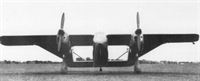
Pressure plottings have indicated that at small angles of incidence, that is to say at high speed, the main wing carries most of the load, the “side wings” serving mainly as fairings for the tail booms. At large angles, however, the airflow changes and the side wings carry a greater proportion of the total load. This is illustrated in the pressure plotting diagram on the previous page. By using a symmetrical section for the wing tips of the front wing it has been found possible to delay the stalling of the tips until quite large angles of incidence are reached; this, of course, results in a retention of lateral control at large angles.
That the stall has been rendered fairly innocuous is shown by the lift curves on p. 145. Although a maximum lift is reached at an angle of about 16-18 degrees, the drop in the lift curve is very gentle, and the subsequent rise tends to restore the small amount of drop at still greater angles. Although the airflow around such a form as the Delta is unusual and somewhat difficult to follow, it appears that at large angles the front wing begins to stall, but the increase of lift on the side wings prevents the sudden drop in the overall lift coefficient curve which one associates with the orthodox high-aspect ratio wing.
It is a matter of some difficulty to assess such things as lift coefficient and form drag. For calculating the former one must take some specific wing area, and in the Delta it is possible to include or omit so many portions of the airform that there is no really satisfactory basis. If one includes the area of the front wing only, the lift coefficient is probably high, but if the total projected area is used it may appear somewhat low. In the large size, for which the design was developed, that would give an unfair picture, because the side wings are used as passenger accommodation.
To get an idea of the “wetted area” figure, one may take as a basis the number of sq. ft. per lb. of gross weight. This amounts, in the large 38,000 lb. machine, to 0.1695. By way of comparison the De Havilland Albatross may be quoted. As a passenger-carrier at 29.500 lb. gross weight, this machine has 0.135 sq. ft. of wetted area per lb. of gross weight. It therefore appears that the surface area of the Delta is relatively greater, but against that must be set the fact that the side wings should count as fuselage area, which is non-productive of lift in the orthodox aeroplane.
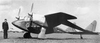
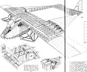
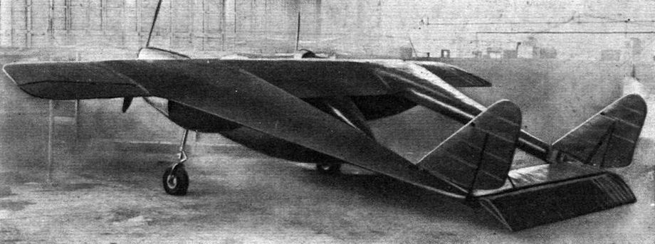
The little two-seater which has been built as a flying model of the large commercial machine is fitted with two Menasco Pirate C.4 engines of 125 h.p. each. The cabin is slung below the front wing, with the occupants seated tandem-fashion. The construction and, incidentally, the curious form caused by the intersection of the front wing with the side wings are well shown in the sketches. The construction is of wood, even to the engine fairings, which have been found to be extremely light. The undercarriage does not retract, the Palmer wheels being carried on cantilever struts.
Except as an indication of the drag of the machine, performance figures are of little value when applied to the small machine, which was built for demonstrating the principle rather than as a practical aeroplane. It is estimated that the top speed will be in the neighbourhood of 185 m.p.h. The machine is, however, less clean that the large commercial type.
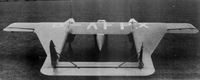
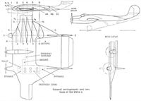
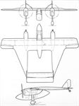
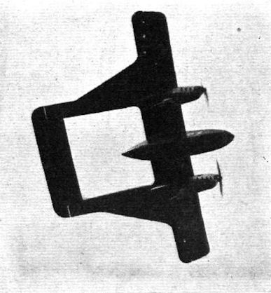
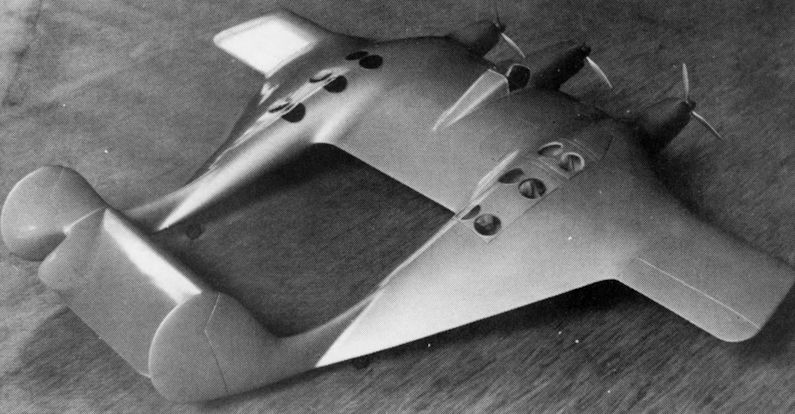
Known as the type Delta 9, the larger machine will have a gross weight of 38,000 lb. and will have accommodation for 18 passengers in each of the two side wings. Its general lines are shown in the drawing (p. 146), and in the photograph of a scale model. The intention is that three liquid-cooled engines of 1,000 h.p. each should be used. Each cabin is 18ft. long, 8ft. wide, and with a central gangway giving not less than 6ft. headroom. Retractable undercarriages are to be fitted, and a special design has been prepared, for which the company holds a patent. A tricycle arrangement could be incorporated.
Owing to the distribution of the load, a low structure weight is achieved, and it is estimated that the Delta 9 should carry as disposable load approximately the equivalent of its tare weight. That has, of course, been achieved before in orthodox aircraft, but never before, so far as we are aware, in a machine which does not stall, in the ordinary sense of the term.
How passengers would take to cabins in which they obtained no direct view of the ground is another matter. Mr. Willoughby has schemed out an arrangement of lenses and ground glasses in the tables of the cabin whereby passengers would be provided with a reduced but very brilliant view of the ground below them. As the tendency seems to be towards flying at greater heights, at which nothing much can be seen anyway, it may be that the question of view for passengers will be regarded as of minor importance in the future.
- Flight, February 9, 1939
DELAYING the STALL
Фотографии

-

Aeroplane Monthly 1981-07 / A.Ord-Hume - The Willoughby Delta
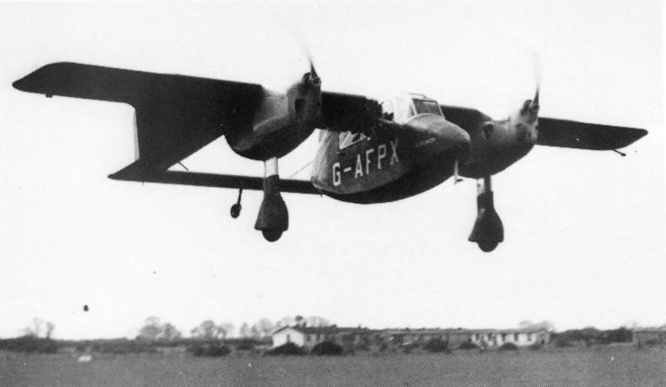
Регистрационный номер: G-AFPX [10] The Delta flying at Witney in May 1939.
-
Air-Britain Archive 1980-04 / U.K. C of A Applications (4)
Регистрационный номер: G-AFPX [10] The Willoughby Delta F G-AFPX appeared at the Heathrow Garden Party on 14.5.39 but survived less than two months, crashing on 10.7.39 and killing the designer. Name on the nose is "St.Francis".
-
Aeroplane Monthly 1981-07 / A.Ord-Hume - The Willoughby Delta
Регистрационный номер: G-AFPX [10] The little Delta shows its unique plan view at Witney in May 1939.
-

Flight 1939-05 / Flight
Регистрационный номер: G-AFPX [10] Another exhibit which aroused interest was the thoroughly unconventional Willoughby Delta (right).
-
Aeroplane Monthly 1981-07 / A.Ord-Hume - The Willoughby Delta
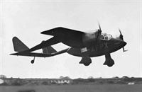
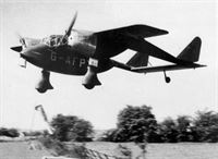
Регистрационный номер: G-AFPX [10] The Delta flying shortly after its initial flight, at Witney in April 1939.
-
Aeroplane Monthly 1981-07 / A.Ord-Hume - The Willoughby Delta
Регистрационный номер: G-AFPX [10] P. N. Willoughby standing by the Delta in May 1939.
-

Flight 1939-02 / Flight
Регистрационный номер: G-AFPX [10] -
Aeroplane Monthly 1981-07 / A.Ord-Hume - The Willoughby Delta
Регистрационный номер: G-AFPX [10] View of the Delta at Witney, May 1939. Note the small area of ailerons.
-
Aeroplane Monthly 1981-07 / A.Ord-Hume - The Willoughby Delta
Регистрационный номер: G-AFPX [10] View of the Delta at Witney, May 1939.
-
Aeroplane Monthly 1981-07 / A.Ord-Hume - The Willoughby Delta
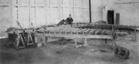
Регистрационный номер: G-AFPX [10] The Delta wing under construction, seen upside down in its jig, Witney, 1938.
-

Aeroplane Monthly 1981-07 / A.Ord-Hume - The Willoughby Delta
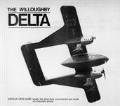
Scale model of the Delta 9. In each side wing is a cabin seating 18 passengers. Three liquid-cooled engines of 1,000 h.p. each are foreseen.
-
Flight 1939-02 / Flight
The Willoughby Delta 8. The machine is mainly of wood construction. The inner spars of the side wings are slipped through the rear spar of the front wing, as shown on the right.
-
Flight 1939-02 / Flight
General arrangement and sections of the Delta 9.
-
Aeroplane Monthly 1981-07 / A.Ord-Hume - The Willoughby Delta
General arrangement of the Delta 8.


- Фотографии