
Фотографии

-
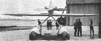
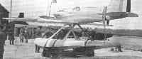
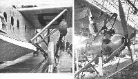
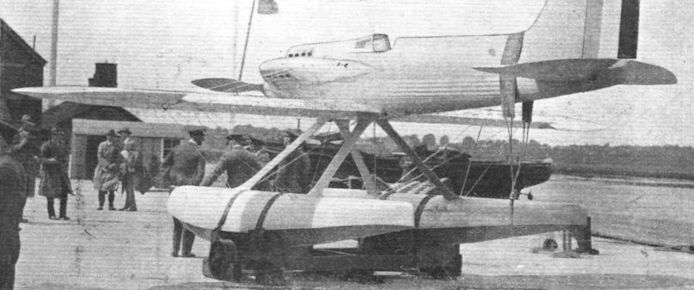
THE SUPERMARINE S.5: This view give an excellent idea of the clean lines of the machine. Note particularly how neatly the Napier "Lion" racing engine is faired into the fuselage.
Самолёты на фотографии: Supermarine S.5 / S.6 - Великобритания - 1927
-
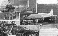
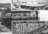
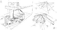
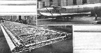
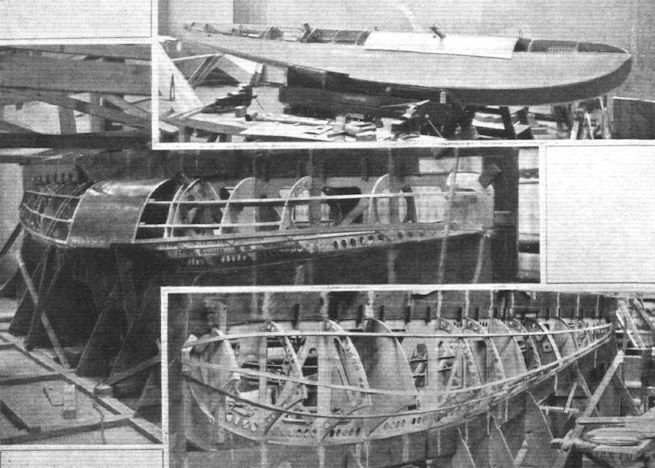
THE SUPERMARINE S.5: Three views of the all-metal fuselage. The lower photograph shows it in skeleton. In the centre the fuselage is seen undergoing sand loading test, and in the upper picture the Napier "Lion" racing engine has been dropped into place. Note the supports for the cylinder block fairing.
Самолёты на фотографии: Supermarine S.5 / S.6 - Великобритания - 1927
-
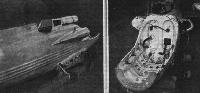
THE SUPERMARINE S.5: On the left, a three-quarter rear view of the fuselage, showing wind screen and cylinder block fairings. On the right, a view inside the engine cradle.
Самолёты на фотографии: Supermarine S.5 / S.6 - Великобритания - 1927
-
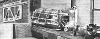
THE SUPERMARINE S.5: The steel centre portion of the starboard float, which forms the petrol tank. Standing on end is the water header tank, and on the right the oil tank. The small inset shows a section of the central bulkhead of the steel portion of the float.
Самолёты на фотографии: Supermarine S.5 / S.6 - Великобритания - 1927
-
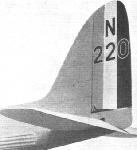
Регистрационный номер: N220 THE SUPERMARINE S.5: The tail of the Schneider Trophy Winner. The control cranks are inside the stern portion of the fuselage.
Самолёты на фотографии: Supermarine S.5 / S.6 - Великобритания - 1927
-

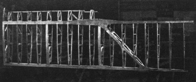
Photograph of one wing of the S.5. Note the diagonal member which stiffens the wing tip against torsion.
Самолёты на фотографии: Supermarine S.5 / S.6 - Великобритания - 1927
-
THE SUPERMARINE S.5: Three views of a float, in skeleton, with the petrol tank installed, and finished, except for the deck planking.
Самолёты на фотографии: Supermarine S.5 / S.6 - Великобритания - 1927
-
Самолёты на фотографии: Supermarine S.5 / S.6 - Великобритания - 1927
-

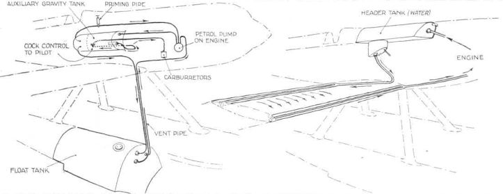
THE SUPERMARINE S.5: On the left, a diagrammatic perspective view of the petrol system, and, on the right, a similar representation of the water system.
Самолёты на фотографии: Supermarine S.5 / S.6 - Великобритания - 1927
-
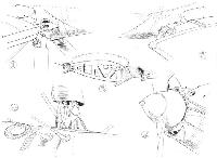
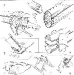
THE SUPERMARINE S.5: Some constructional details. 1, Water pipes in leading edge from wing radiators. Note also petrol pipes from float in strut fairing. 2, the water pipes from the trailing edge enter the fuselage at the wing root. 3, the starboard wing root. Note the water pipe inside. 4, details of the float strut and petrol pipes where they enter the starboard float. The filler cap of the tank is also shown. 5, propeller boss, spinner and air scoops for cooling the engine gear.
Самолёты на фотографии: Supermarine S.5 / S.6 - Великобритания - 1927
-
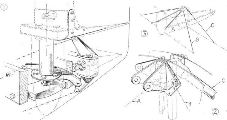
THE SUPERMARINE S.5: 1, Details of rudder and elevator cranks inside stern of fuselage. The elevator crank is offset to clear the rudder post. 2, the fittings at the top of the fuselage to which are anchored the antilift wires. This point stabilises the entire bracing system. 3, diagrammatic perspective view of two main frames, with bracing wires and tubes, engine bearers and engine mounting.
Самолёты на фотографии: Supermarine S.5 / S.6 - Великобритания - 1927
-
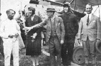
The Port Elizabeth Club: On the left of Lady Heath is Major Miller, who is prominently associated with civil aviation in South Africa, and has helped in the formation of the clubs by flying his own D.H. "Moth," and raising funds. On the right is the Lord Mayor of Port Elizabeth, then comes Capt. Swann, the Club's instructor, and finally, Mr.Hurch, President of the Club. In the background is the nose of the Westland "Widgeon."
Самолёты на фотографии: Westland Widgeon - Великобритания - 1924
-
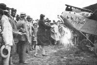
With the South African Clubs: Lady Heath performing the christening ceremony of the Port Elizabeth Club's machine, the Westland "Widgeon." It was christened "The Lady Heath." The Lord Mayor of the town is seen third from the left.
Самолёты на фотографии: Westland Widgeon - Великобритания - 1924
-

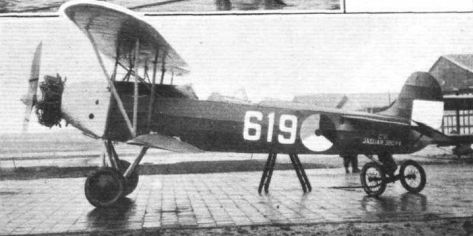
THE ARMSTRONG-SIDDELEY ABROAD: Successful Fokker-Armstrong Siddeley combination. C.VI reconnaissance machine, which is fitted with the 385 h.p. "Jaguar."
Самолёты на фотографии: Fokker C.V / C.VI - Нидерланды - 1924
-
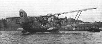
Регистрационный номер: G-EBUP SIR ALAN COBHAM AT MALTA: Our picture shows Sir Alan's Short all-metal "Singapore" flying-boat (Rolls-Royce "Condor" engines) in Valletta Harbour, prior to resuming the flight to Africa on January 21, after an enforced stay of over five weeks.
Самолёты на фотографии: Short Singapore I / S.5 - Великобритания - 1926
-
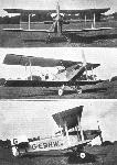
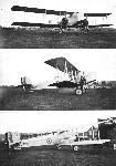
Регистрационный номер: G-EBNW, N239 AN AVRO TORPEDO BOMBER: Three views of the "Buffalo II" with Napier "Lion XA." Special features are the extremely "clean" nose and the slot-and-aileron control. The wings are swept back, and are designed to fold. The performance is believed to be very good.
Самолёты на фотографии: Avro Buffalo / Type 571/572 - Великобритания - 1927
-
HINKLER'S FLIGHT TO AUSTRALIA: On the left, the "Great Little Man" is seen at work on his engine. On the right a "close-up" of the special vice Hinkler has made. This fits on an engine bearer, and enables work, such as adjusting a tappet rod or dismantling a sparking plug, to be carried out with convenience. The short air intake pipe has, where it joins the carburettor a "choke plate" which Hinkler uses for starting, in place of the usual rag. The "Avian" bristles with special "gadgets" thought out by Hinkler.
Самолёты на фотографии: Avro Avian / Type 594/616 - Великобритания - 1926
-

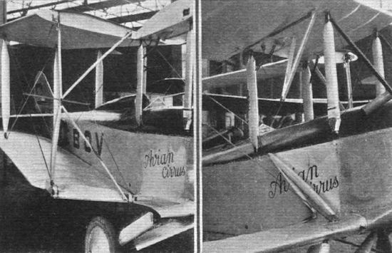
Регистрационный номер: G-EBOV [2] HINKLER'S FLIGHT TO AUSTRALIA: Two views of the special "K" type jury strut used by Hinkler for folding the wings of his "Avian". The photograph on the left shows the "K" strut in place, while on the right it is seen partly folded. A single bolt in the centre is undone, and the two halves of the "K" strut then fold into lower and upper wing respectively, where they are housed in slots in such a way as to fair in with the wing surfaces.
Самолёты на фотографии: Avro Avian / Type 594/616 - Великобритания - 1926
-

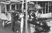
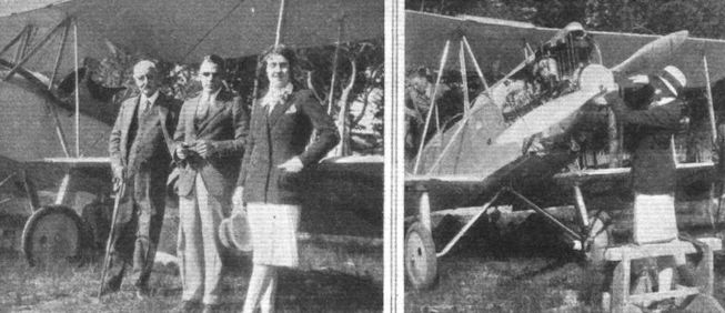
SNAPSHOTS FROM SOUTH AFRICA: On the left are Lady Heath, Mr. Brian Russell and Sir James Heath standing before the former's Avro "Avian," which was in course of erection at Young's Field, the aerodrome outside Cape Town. On the right is Lady Heath tightening up the propeller, whilst other energetic workers are seen under the machine and in the rear cockpit.
Самолёты на фотографии: Avro Avian / Type 594/616 - Великобритания - 1926
-
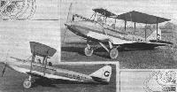
Регистрационный номер: G-EBVI This is the Avro "Avian" which A. V. Roe and Co. have supplied to the Hampshire Aero Club. It is fitted with the new undercarriage which is automatically swept back when the wings are folded, bringing the machine nearer the ground. Thus the engine is more accessible for inspection and adjustment. Also a good deal of weight is taken off the tail skid, thereby facilitating the manoeuvring of the machine. These photographs were taken at Woodford Aerodrome, Cheshire, after the machine had been tested.
Самолёты на фотографии: Avro Avian / Type 594/616 - Великобритания - 1926
-

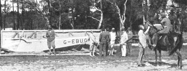
Регистрационный номер: G-EBUG AN "AVIAN" IN SOUTH AFRICA: In this interesting group discussing the unpacking of Lady Heath's "Avian" at Cape Town will be noticed Sir James Heath (with walking stick) and Lady Heath, whilst stroking the glossy neck of the horse is Col. Henderson. The lady rider is Miss Jute, of Johannesburg, who learned to fly with Col. Henderson and was ready to go solo within a week.
Самолёты на фотографии: Avro Avian / Type 594/616 - Великобритания - 1926
-
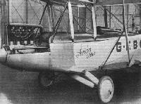
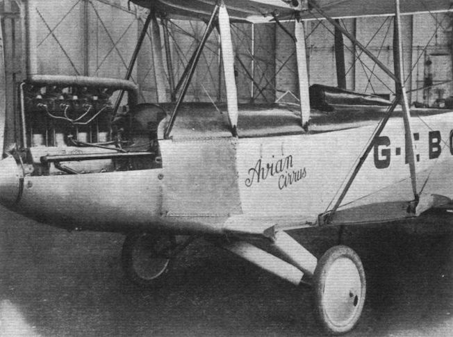
Регистрационный номер: G-EBOV [2] HINKLER'S FLIGHT TO AUSTRALIA: This view of the "Avian" with wings folded gives a good idea of the way in which Hinkler's special type of undercarriage lowers the front of the machine and makes the "Cirrus" engine very accessible. Also the wheels move aft and relieve the tail skid of nearly all its load.
Самолёты на фотографии: Avro Avian / Type 594/616 - Великобритания - 1926
-

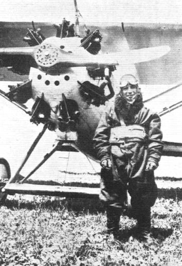
SEVEN-AND-A-QUARTER MILES HIGH: Comm. Donati, the Italian pilot, who recently attained an altitude of 11,852 m. (38,886 ft.) on an Ansaldo-Dewoitine monoplane fitted with an Alfa-Romeo "Jupiter" engine. He is seen wearing his special flying kit and "Salvator" parachute.
Самолёты на фотографии: Dewoitine D.1 / D.9 - Франция - 1922
-
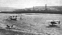
Регистрационный номер: G-EBVG [4] ON THE MEDWAY: This little seascape is of interest in showing three Short machines moored. In the background is the "Calcutta." On the left, the little "Mussel," which has been moored out for more than 2,000 hours, and on the right the "Sturgeon"
Самолёты на фотографии: Short Calcutta / Rangoon / S.8 - Великобритания - 1928Short Mussel / S.7 - Великобритания - 1926Short Sturgeon / S.6 / Gurnard / S.10 - Великобритания - 1927
-
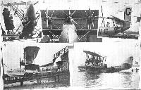
Регистрационный номер: G-EBVG [4] EMPIRE AIR COMMUNICATIONS: Launch at Rochester of the first of the Short "Calcutta" flying-boats with three Bristol "Jupiter" engines built for Imperial Airways, Ltd. 1. The Mayoress of Rochester christening the machine. 2. Front view showing the "Jupiter" engines. 3. The tail of the "Calcutta." Note the servo rudder. 4 and 5. Views of the machine on the slipway and afloat after the launch.
Самолёты на фотографии: Short Calcutta / Rangoon / S.8 - Великобритания - 1928
-
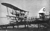
Регистрационный номер: G-EBVG [4] THE SHORT "CALCUTTA": The machine on the slipway. Note the open luggage hatch.
Самолёты на фотографии: Short Calcutta / Rangoon / S.8 - Великобритания - 1928
-
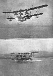
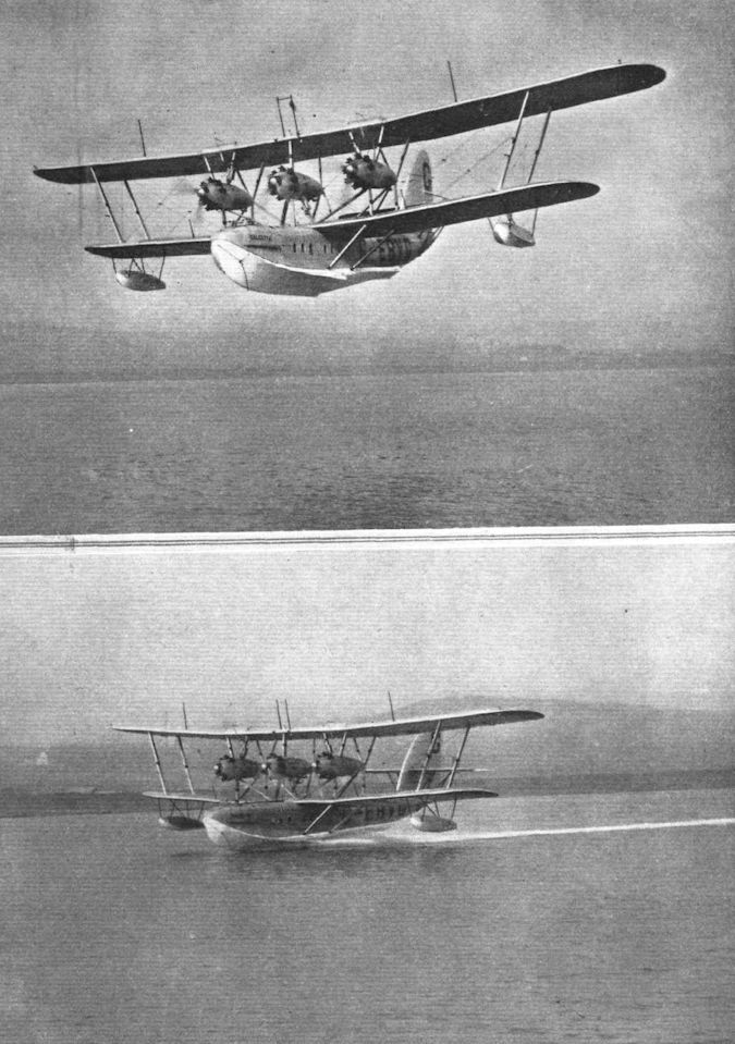
Регистрационный номер: G-EBVG [4] THE SHORT "CALCUTTA": Views of the machine "planing" and in flight. In the lower photograph, note should be taken of the particularly "clean" running. The "Calcutta" will not only fly on two engines but will take off on two.
Самолёты на фотографии: Short Calcutta / Rangoon / S.8 - Великобритания - 1928
-
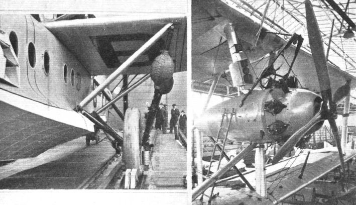
THE SHORT "CALCUTTA": On the left, a "close-up" of the beaching chassis. The front hatch, which also forms steps, can just be seen. On the right, the port wing engine. Above the nacelle can be seen the crane, used for lifting the engines into and out of the machine. In the photograph, the engine has open exhaust. A collector ring, shaped liked the cowl in the photograph, will be fitted later.
Самолёты на фотографии: Short Calcutta / Rangoon / S.8 - Великобритания - 1928
-
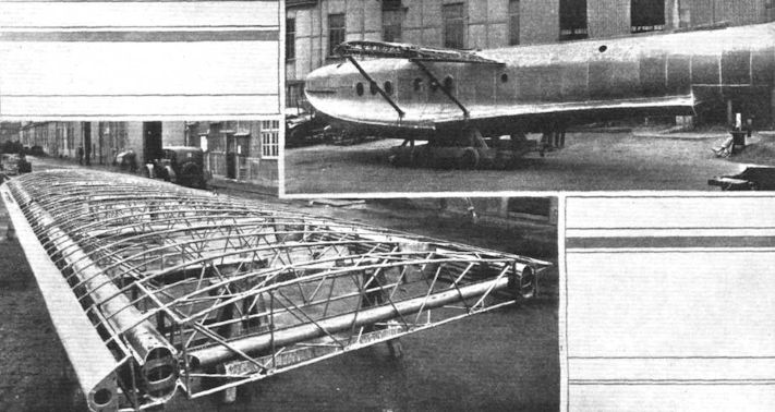
THE SHORT "CALCUTTA": On the left, a wing in skeleton, and on the right, the hull, Note particularly the faired rear step.
Самолёты на фотографии: Short Calcutta / Rangoon / S.8 - Великобритания - 1928
-
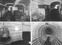
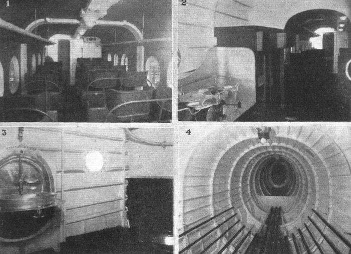
THE SHORT "CALCUTTA": 1, view inside the cabin, looking forward. 2, the galley and buffet. 3, the lavatory, with tip-up wash basin. 4, view in the luggage hold, looking aft.
Самолёты на фотографии: Short Calcutta / Rangoon / S.8 - Великобритания - 1928
-
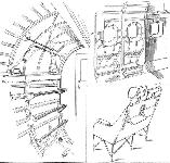
THE SHORT "CALCUTTA" THREE-ENGINED FLYING BOAT: Some constructional details. A section of the rear spar of the top centre-section is shown in 1, with its steel fitting for strut and lift wires, etc. 2, shows a section of the top rear spar. Note the laminations which reinforce the spar at point of attachment of fittings. Built-up compression struts are used, the end of one being illustrated in 3. The spars of the lower centre-section differ slightly in construction, as shown in 4. The curved angle-section piece conforms to the cabin roof, through which this spar passes. The attachment of the raked struts which run from lower plane at engine supports to chine, meet the latter as shown in 5. The two petrol tanks are housed in the top plane, and are of the form shown in 6. Details of the tank supports, incorporating rubber buffers, are shown in 7 and 8.
Самолёты на фотографии: Short Calcutta / Rangoon / S.8 - Великобритания - 1928
-
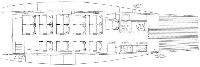
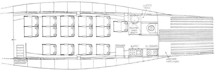
THE SHORT "CALCUTTA": Plan of the passenger accommodation.
Самолёты на фотографии: Short Calcutta / Rangoon / S.8 - Великобритания - 1928
-
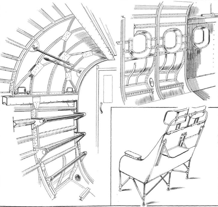
THE SHORT "CALCUTTA": On the left, a view inside the luggage compartment, showing the general construction, the special hatch which also serves as an emergency exit, and the tubular steps. When open, the hatch is kept raised by the two tubes shown folded in their clips. On the right, a portion of the cabin, showing construction, and, right, the finished cabin covered with material. Below is a double seat, with the neat folding tables provided for each passenger.
Самолёты на фотографии: Short Calcutta / Rangoon / S.8 - Великобритания - 1928
-
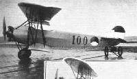
THE ARMSTRONG-SIDDELEY ABROAD: Successful Fokker-Armstrong Siddeley combination. Fokker Training biplane, which is fitted with the 150 h.p. "Mongoose" engine.
Самолёты на фотографии: Fokker S.II / S.III / S.IV - Нидерланды - 1922
-
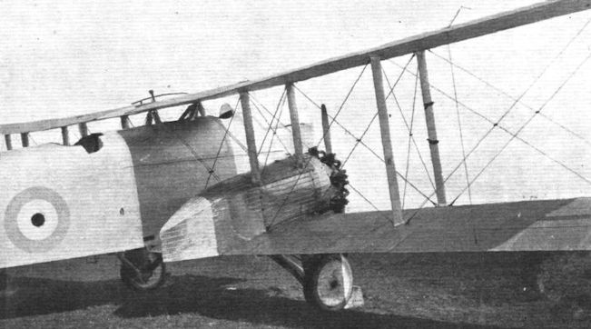
Регистрационный номер: J7765 A THREE-SEATER FIGHTER: The Westland "Westbury," fitted with two Bristol "Jupiter" engines, can also be converted into a high-performance bomber.
Самолёты на фотографии: Westland Westbury - Великобритания - 1926
-

THE WESTLAND "WESTBURY": This view shows the mounting of the starboard "Jupiter," and also the forward cockpits, &c.
Самолёты на фотографии: Westland Westbury - Великобритания - 1926


Статьи
- Flight