
Фотографии
-
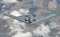
The dividend - the Northrop Grumman B-2 Spirit. Reportedly, Jack Northrop, a lifelong advocate of the flying-wing concept, was given clearance to see designs of the B-2 before his death in 1981. Very ill, he wrote on a piece of paper: “Now I know why God has kept me alive for the last 25 years...”
Самолёты на фотографии: Northrop B-2 Spirit - США - 1989
-

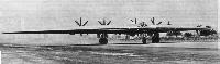
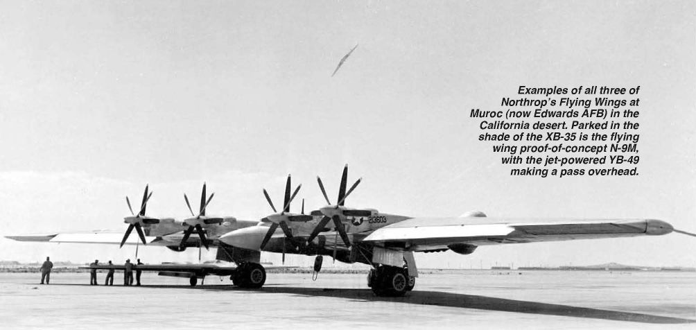
Examples of all three of Northrop’s Flying Wings at Muroc (now Edwards AFB) in the California desert. Parked in the shade of the XB-35 is the flying wing proof-of-concept N-9M, with the jet-powered YB-49 making a pass overhead.
Самолёты на фотографии: Northrop B-35 - США - 1946Northrop B-49 - США - 1947Northrop N-9M - США - 1942
-

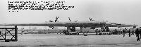
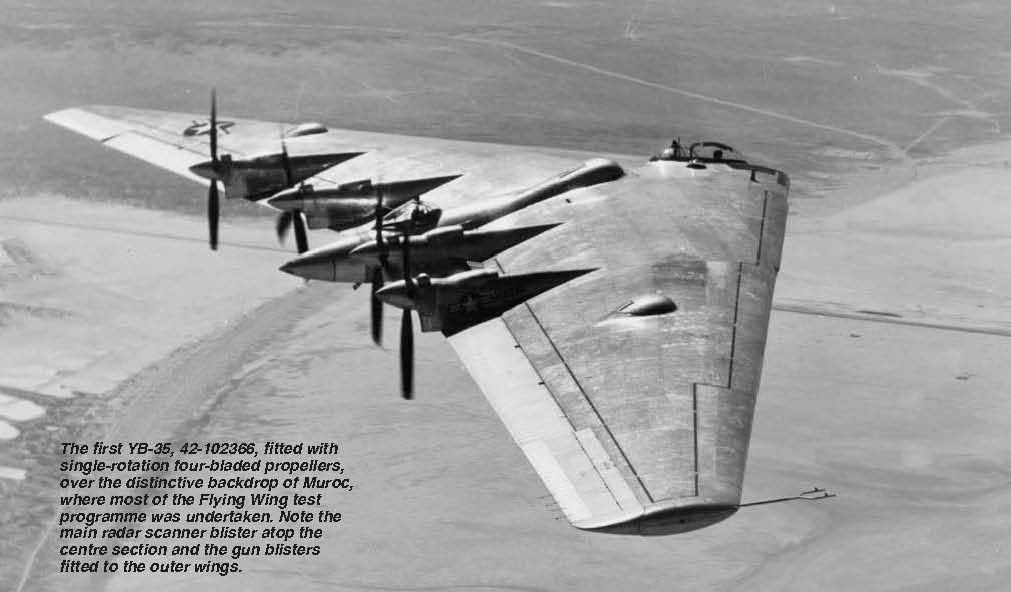
The first YB-35, 42-102366, fitted with single-rotation four-bladed propellers, over the distinctive backdrop of Muroc, where most of the Flying Wing test programme was undertaken. Note the main radar scanner blister atop the centre section and the gun blisters fitted to the outer wings.
Самолёты на фотографии: Northrop B-35 - США - 1946
-
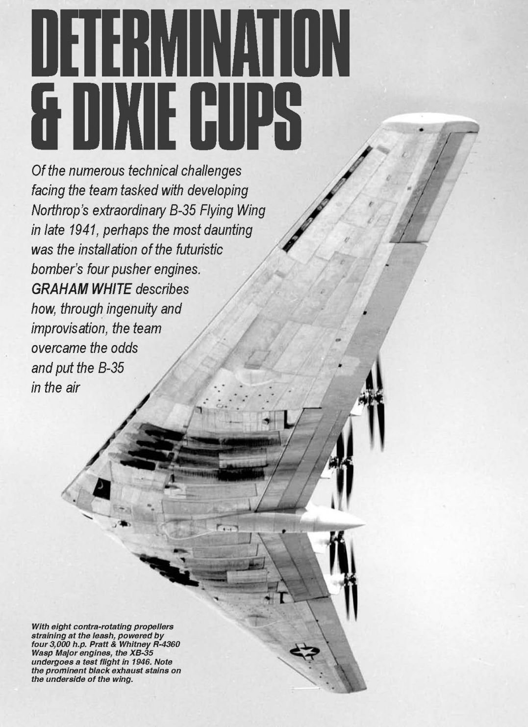
With eight contra-rotating propellers straining at the leash, powered by four 3,000 h.p. Pratt & Whitney R-4360 Wasp Major engines, the XB-35 undergoes a test flight in 1946. Note the prominent black exhaust stains on the underside of the wing.
Самолёты на фотографии: Northrop B-35 - США - 1946
-

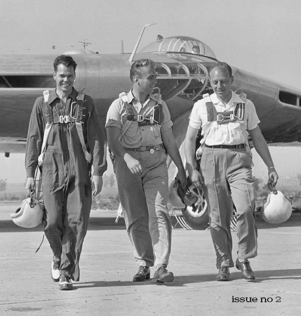
Knowing when to walk away? - the crew of the Northrop XB-35 on its maiden flight. From left to right: Orva Douglas, flight engineer; Fred Bretcher, copilot; Max Stanley, pilot.
Самолёты на фотографии: Northrop B-35 - США - 1946
-
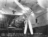
A test rig bearing one of the B-35’s R-4360 engines with extension driveshaft connected to a pair of three-bladed contra-rotating propellers. As with Convair’s B-36, the B-35’s pusher-configuration engines had to be buried in the wing, this type of installation demanding a forced airflow over the engine to augment cooling, particularly on the ground.
Самолёты на фотографии: Northrop B-35 - США - 1946
-
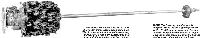
The Pratt & Whitney R-4360-11 four-row 28-cylinder piston engine was used on the XB-35 as the inboard-mounted powerplant, and was fitted with a driveshaft some 21ft long with the propeller reduction gearing mounted at its far end.
Самолёты на фотографии: Northrop B-35 - США - 1946
-
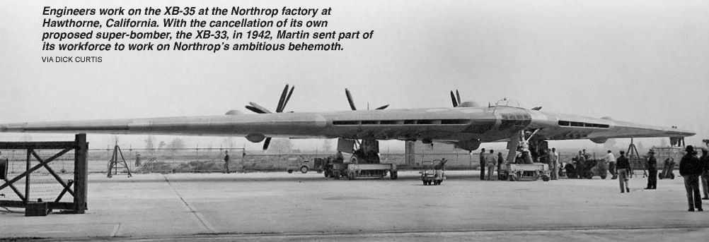
Engineers work on the XB-35 at the Northrop factory at Hawthorne, California. With the cancellation of its own proposed super-bomber, the XB-33, in 1942, Martin sent part of its workforce to work on Northrop’s ambitious behemoth.
Самолёты на фотографии: Northrop B-35 - США - 1946
-
Первый экземпляр XB-35 на разбеге
The XB-35 at Hawthorne, still in its original contra-prop configuration. The subsequent jet-powered YB-49 suffered from control problems, and although Jack Northrop’s flying wing concept failed to gain traction with the military brass of the time, the idea would resurface some 30 years later.Самолёты на фотографии: Northrop B-35 - США - 1946
-
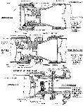
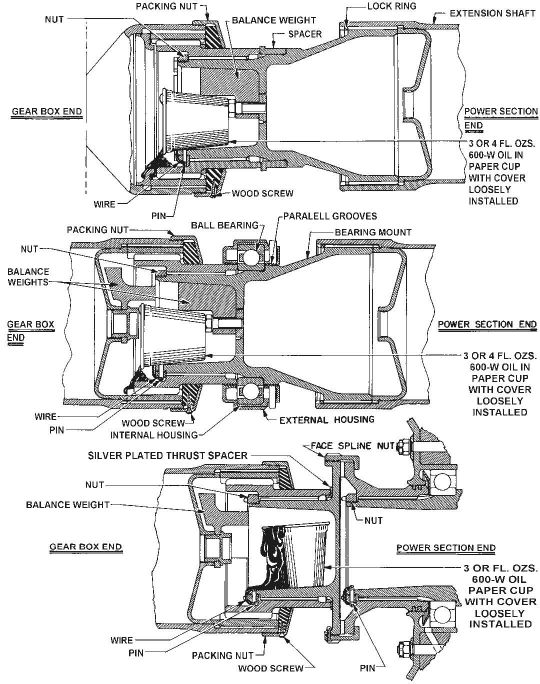
The Dixie cup solution - this diagram shows the shaft bearings for the B-35’s R-4360 and the position of the cup in each. At top is the bearing at the engine end, the middle diagram shows the bearing midway along the shaft and the lower diagram the bearing at the prop end.
Самолёты на фотографии: Northrop B-35 - США - 1946
-
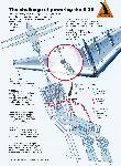
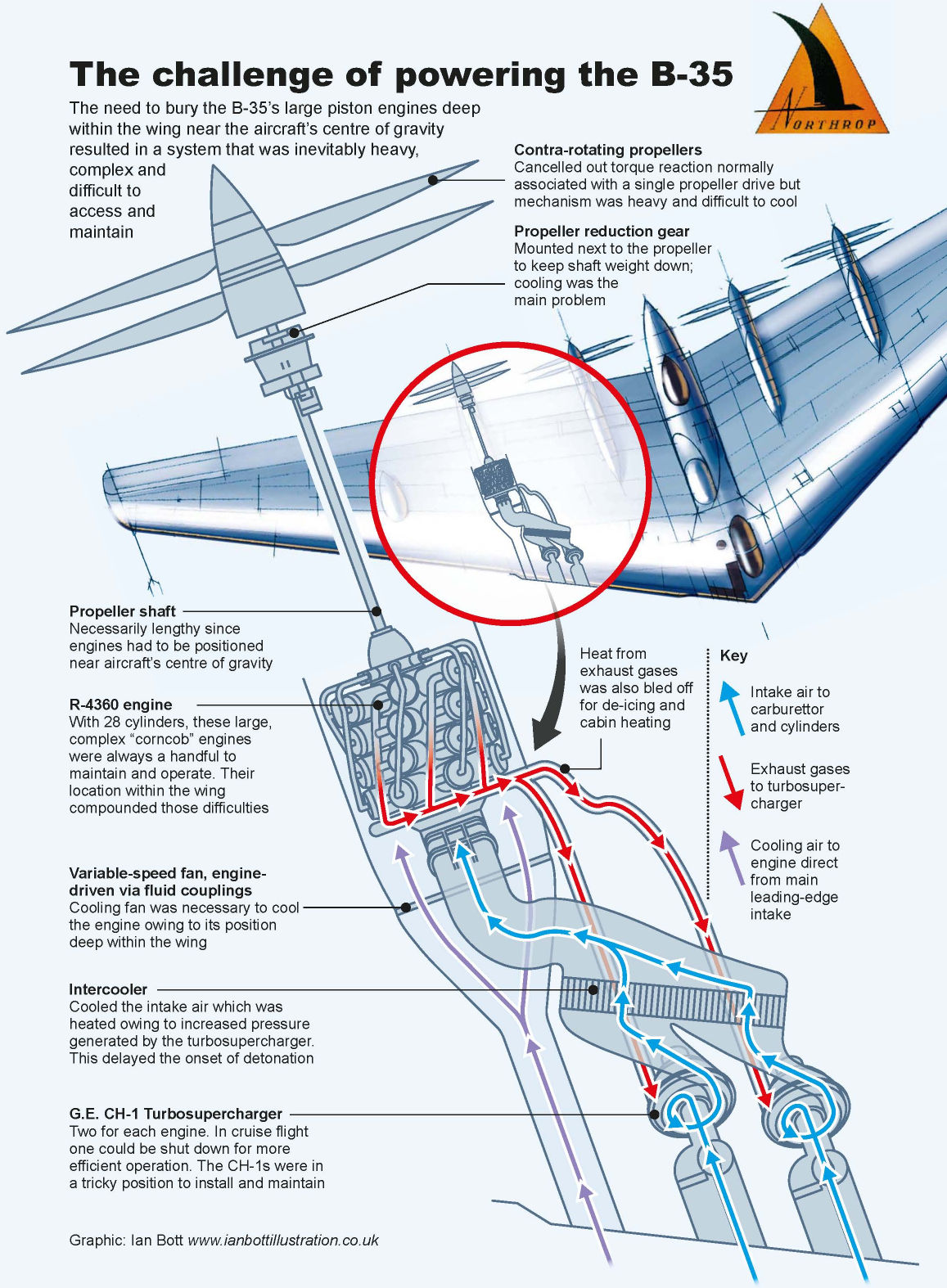
The challenge of powering the B-35. The need to bury the B-35’s large piston engines deep within the wing near the aircraft’s centre of gravity resulted in a system that was inevitably heavy, complex and difficult to access and maintain
Самолёты на фотографии: Northrop B-35 - США - 1946
-

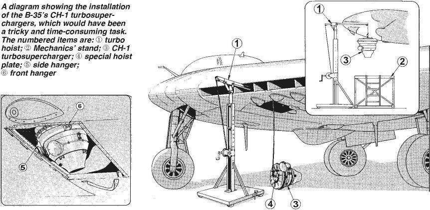
A diagram showing the installation of the B-35’s CH-1 turbosuperchargers, which would have been a tricky and time-consuming task. The numbered items are: 1) turbo hoist; 2) Mechanics’ stand; 3) CH-1 turbosupercharger; 4) special hoist plate; 5) side hanger; 6) front hanger
Самолёты на фотографии: Northrop B-35 - США - 1946


Статьи
- -
- American Classics
- D.Simpson - Hunters over the Andes
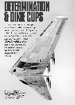
- G.White - Determination & Dixie Cups
- J.de Uphaugh - Lord of the Distances
- J.Forsgren - New Tricks for an Old Seadog
- J.Pote - Anything, Anywhere, Anytime Professionally (1)
- J.Wood - The Lion and its Claws
- N.Stroud - From Skyray to Firebird
- N.Stroud - Sekani
- P.Davidson - Off the Beaten Track...
- P.Jarrett - Lost & Found
- R.Carvell - Ill Wind
- R.Forsyth - Into the Dragon's Lair
- R.Lezon - Buenos Aires & Bust!
- R.Simpson - The Faster Skymaster
- R.Tisdale, A.Vercamer - Before & After