Фотографии
-

Aviation Historian 21 / B.Harrison - Fairey's commercial break
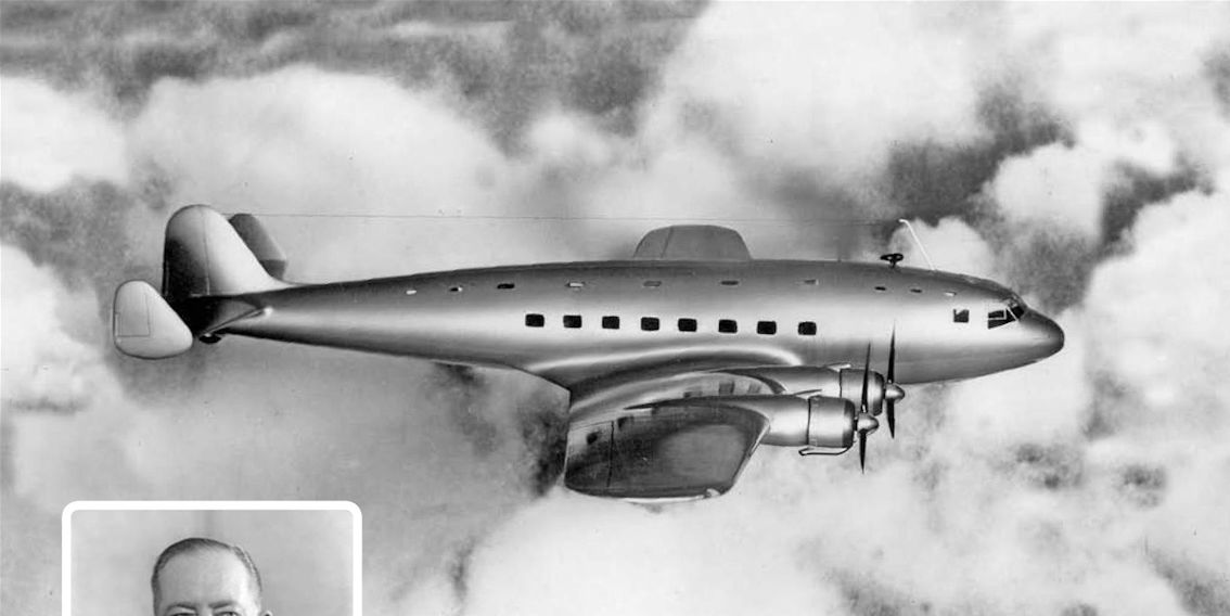
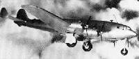
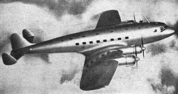
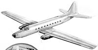
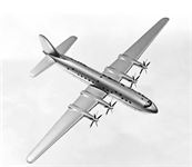
Another photo-montage of the FC.1 “in flight”, looking very much like a cross between the shapely de Havilland Albatross airliner, which first flew in May 1937, and the triple-finned American Lockheed Constellation, the design of which did not start until 1939, and which made its maiden flight in January 1943.
-

Flight 1939-04 / Flight
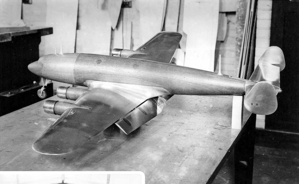
This picture of a model of the Fairey F.C-1. gives a good idea of how the machine will look. It is possible that the triple-rudder arrangement will give way to a twin-rudder type of tail. The engines will be Bristol Taurus of about 1,000 h.p. each; it is expected to cruise at 220 m.p.h.
-
Flight 1938-12 / Flight
A model of the new Fairey commercial machine ordered by the Air Ministry.
-

Aviation Historian 21 / B.Harrison - Fairey's commercial break
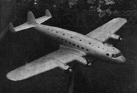
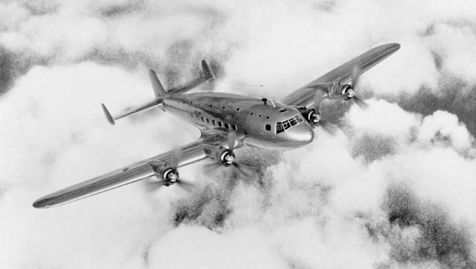
A promotional photo-montage of a model of the FC.1 “in flight” over a generic cloudscape. By this stage the airliner has had a central fin incorporated but still has a deep cockpit window configuration. By the time work on the mock-up started, a more streamlined windscreen arrangement with smaller windows had been designed.
-
Air Enthusiast 1972-09 / H.Taylor - A Short Fairey Tale ... still-born airliners of the 'thirties
Model of the Fairey F.C.1, showing undercarriage.
-

Aviation Historian 21 / B.Harrison - Fairey's commercial break
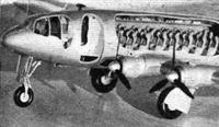
Windtunnel tests of the FC.1 were undertaken with this beautiful handmade model, seen here without a central fin and with the Fairey-Youngman flaps extended. The model incorporates a tricycle undercarriage, although a tailwheel arrangement was also considered.
-
Flight 1938-12 / Flight
The forward portion of the model of the new Fairey four-engined transport which will have a nose wheel of substantial proportions.
-
Aviation Historian 21 / B.Harrison - Fairey's commercial break
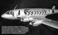
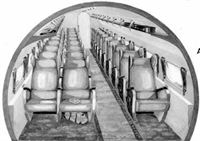
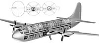
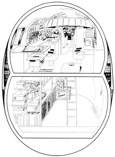
A company model with cutaways showing the proposed internal layout of the FC.1. The passengers were to be accommodated in several rows comprising two seats either side of a central aisle, with overhead compartments for light items of luggage. The wireless operator would be stationed behind the co-pilot’s right-hand seat in the flightdeck compartment.
-
Aviation Historian 21 / B.Harrison - Fairey's commercial break
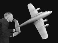
A scale model of the Fairey FC.1 is held aloft by John W.R. Taylor, who worked for the company in his early years before going on to become one of the UK’s most distinguished aviation authors. Of ultra-modern design, the FC.1 is seen here without the central fin added ata later stage.
-

Flight 1939-07 / Flight
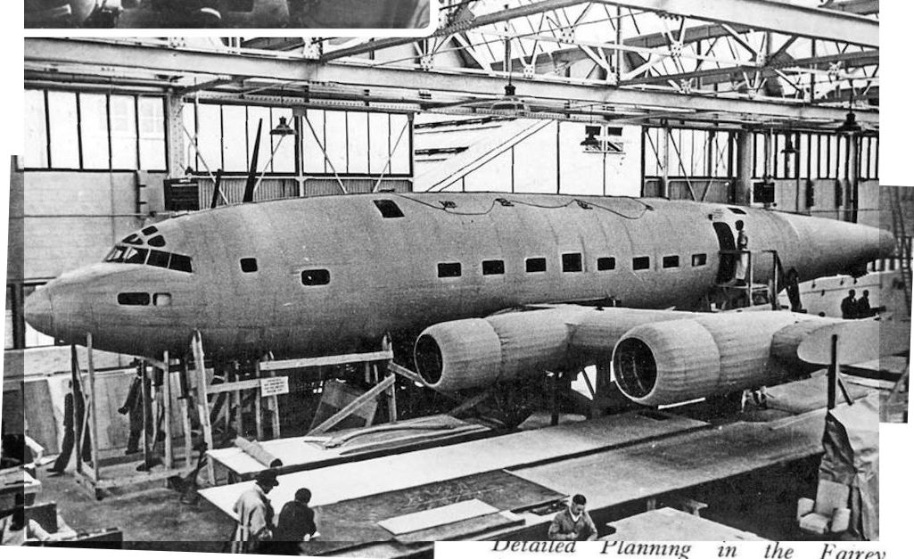
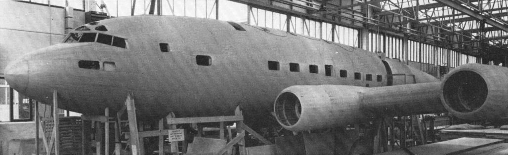
The mock-up is one of the most realistic and complete we have ever seen.
-

Air Enthusiast 1972-09 / H.Taylor - A Short Fairey Tale ... still-born airliners of the 'thirties
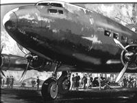
The full-scale wood and paper mock-up of the F.C.1 in the company's experimental shop, probably late in 1938.
-
Air Enthusiast 1972-09 / H.Taylor - A Short Fairey Tale ... still-born airliners of the 'thirties
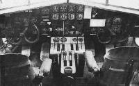
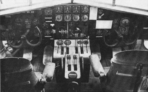
By the spring of 1939 the FC.1 mock-up was nearing completion in the company’s experimental workshop at Hayes and incorporated flight instrumentation in the cockpit, including the central control pedestal and a Sperry autopilot panel.
-


-
Aviation Historian 21 / B.Harrison - Fairey's commercial break
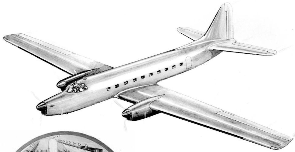
An official Fairey illustration of its first post-war design study for an airliner, the FC.2, which was to be powered by three Rolls-Royce Merlin T.24 engines. This was to be Stage I, with the trimotor configuration giving way to a pair of wing-mounted turboprops in due course.
-
Aviation Historian 21 / B.Harrison - Fairey's commercial break
The FC.2’s proposed passenger cabin layout had rows of twin seats on the starboard side, with singles on the port side, separated by an offset aisle. The Merlin T.24 was a specialised version of the two-speed supercharged Mk 24, developed for improved service life for use with RAF Transport Command’s Lancasters, Lancastrians and Yorks.

-
Aviation Historian 21 / B.Harrison - Fairey's commercial break
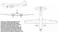
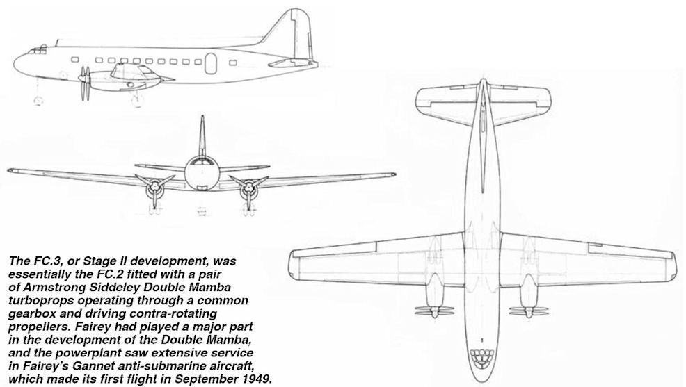
The FC.3, or Stage II development, was essentially the FC.2 fitted with a pair of Armstrong Siddeley Double Mamba turboprops operating through a common gearbox and driving contra-rotating propellers. Fairey had played a major part in the development of the Double Mamba, and the powerplant saw extensive service in Fairey’s Gannet anti-submarine aircraft, which made its first flight in September 1949.
-
Aviation Historian 21 / B.Harrison - Fairey's commercial break
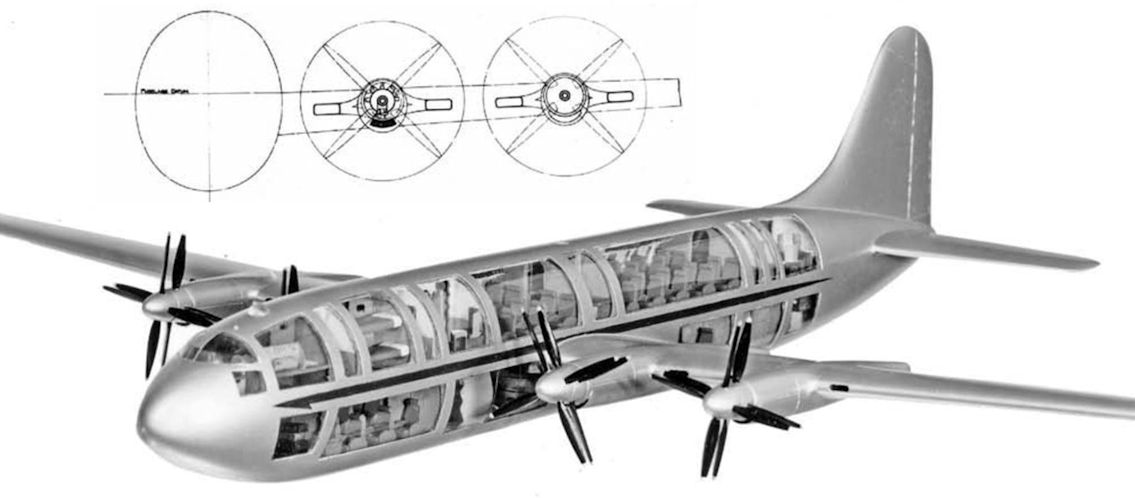
A foretaste of the 21st-century double-deck Airbus A380, the Fairey Queen (as the FC.4 to FC.6 were collectively known) was to accommodate up to 58 passengers in a two-tiered "double-bubble" fuselage. The powerplants were to be accommodated in highly streamlined nacelles, as seen in the head-on view of the FC.4 in the Fairey illustration at TOP.
-
Aviation Historian 21 / B.Harrison - Fairey's commercial break
Another view of the Fairey Queen model, which highlights the design’s clean lines and high-aspect-ratio wing. Various powerplants were mooted for the design, chiefly the Bristol Proteus which powered the Bristol Britannia airliner and Saro Princess flying-boat, and the Napier Nomad turbo-diesel with contra-rotating propellers.
-
Aviation Historian 21 / B.Harrison - Fairey's commercial break
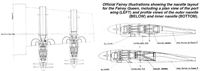
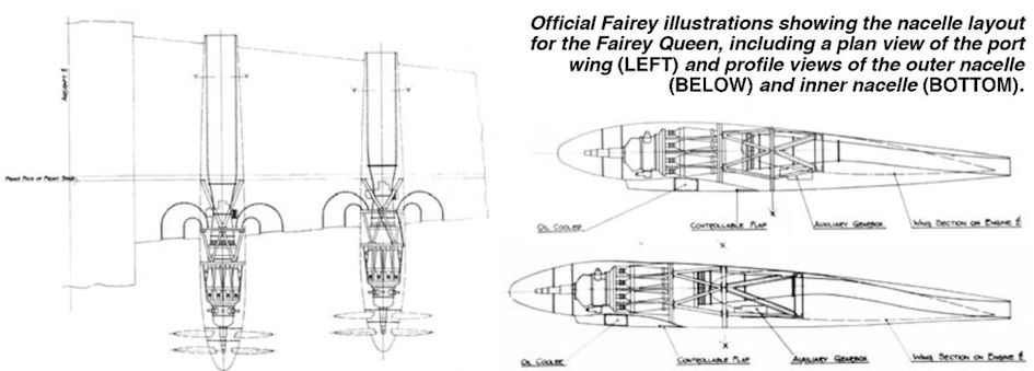
Official Fairey illustrations showing the nacelle layout for the Fairey Queen, including a plan view of the port wing (LEFT) and profile views of the outer nacelle (BELOW) and inner nacelle (BOTTOM).
-

Aviation Historian 21 / B.Harrison - Fairey's commercial break
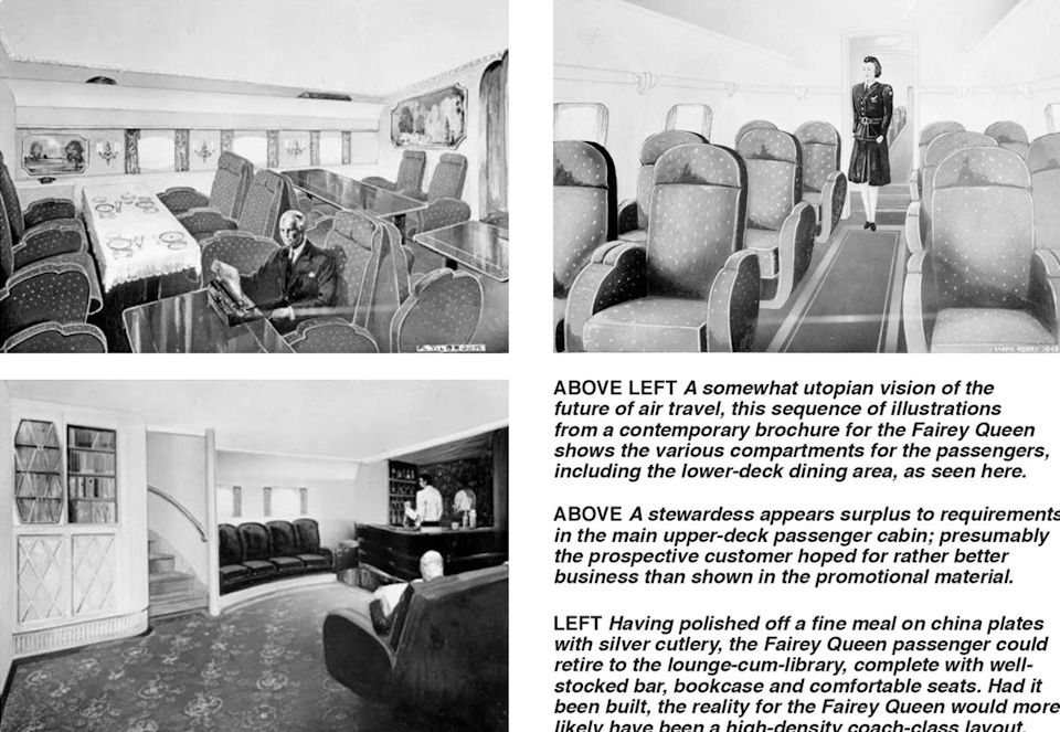
TOP LEFT A somewhat utopian vision of the future of air travel, this sequence of illustrations from a contemporary brochure for the Fairey Queen shows the various compartments for the passengers, including the lower-deck dining area, as seen here.
TOP RIGHT A stewardess appears surplus to requirements in the main upper-deck passenger cabin; presumably the prospective customer hoped for rather better business than shown in the promotional material.
BOTTOM LEFT Having polished off a fine meal on china plates with silver cutlery, the Fairey Queen passenger could retire to the lounge-cum-library, complete with well-stocked bar, bookcase and comfortable seats. Had it been built, the reality for the Fairey Queen would more likely have been a high-density coach-class layout. -
Aviation Historian 21 / B.Harrison - Fairey's commercial break
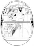
A contemporary Fairey illustration of a crosssection of the forward part of the Fairey Queen’s double-bubble fuselage, with the capacious freight hold beneath the flightdeck. Note also the equipment ducts running in the voids between the curved upper and lower fuselage sections, making servicing easier.

-

Flight 1939-01 / Flight
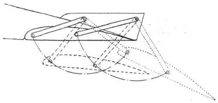
The invention which has made the F.C.1 possible. Diagrammatic representation of the Fairey auxiliary aerofoil, which can be used both for take-off and landing, according to its position. The rear links are partly housed in fairings on top of the main wing.
-
Aviation Historian 21 / B.Harrison - Fairey's commercial break
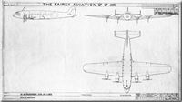
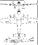
An original Fairey general arrangement drawing of the FC.1 with Bristol Taurus engines to Air Ministry Specification 15/38, dated July 1, 1938. The first choice of powerplant for the FC.1 had been the Rolls-Royce Exe, an X-type sleeve-valve engine, but the company suspended its development to concentrate on Merlin production.
-
Air Enthusiast 1972-09 / H.Taylor - A Short Fairey Tale ... still-born airliners of the 'thirties
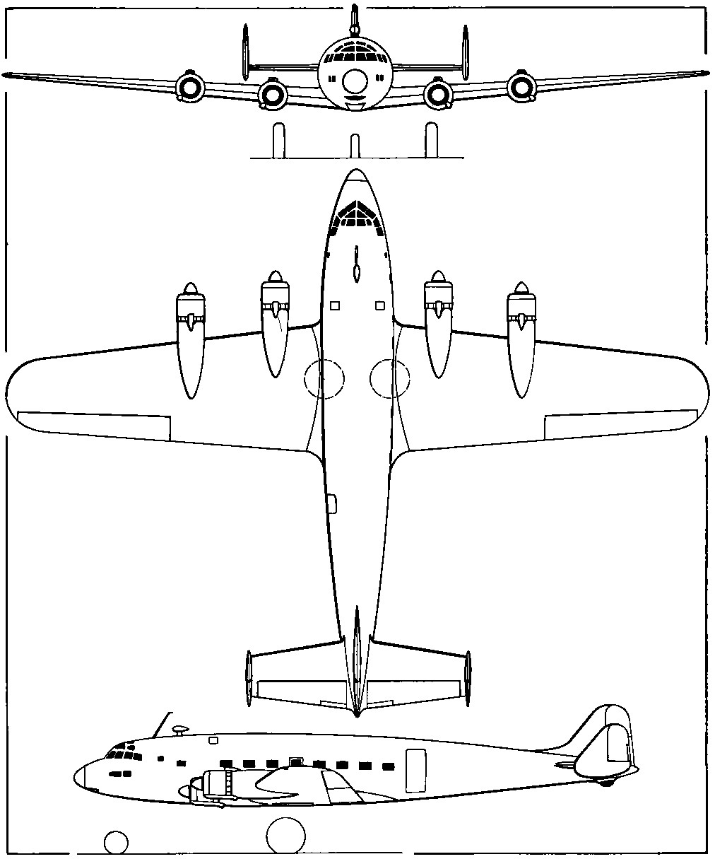
General arrangement drawing of the Fairey F.C.1.