Bernard 12
<...>
В 1922 году фирма ЕАВ была преобразована в SIMB ("Societe Industrielle des METAUX et du Bois"), в которой под руководством нового главного конструктора Жана Хуберта был спроектирован прототип истребителя - свободнонесущий низкоплан Bernard 10. В 1926-1927 годах фирма была преобразована в SAB ("Societe des Avions Bernard"), первым самолетом которой стал Bernard 20.
Bernard 12 отличался от Bernard 10 конструкцией шасси, звездообразным мотором, установленным вместо V-образного, и более мощным пулеметным вооружением. Первый полет Bernard 12 выполнил в мае 1926 года с двигателем Gnome-Rhone (Bristol) Jupiter. Самолет запустили в производство как C.1 (Chasse monoplace - одноместный истребитель), оснастив его двигателем Hispano-Suiza или Lorraine мощностью 500 л. с. В 1920-е годы французские военные с сомнением относились к идее истребителя-моноплана, а потому дальнейшие работы по истребителям марки Bernard развития не получили.
ТАКТИКО-ТЕХНИЧЕСКИЕ ХАРАКТЕРИСТИКИ
Bernard 12
Тип: одноместный истребитель
Силовая установка: один звездообразный мотор Gnome-Rhone (Bristol) Jupiter 9Ab мощностью 420л.с.(313кВт)
Характеристики: максимальная скорость на оптимальной высоте 265 км/ч; практический потолок 8000 м
Масса: пустого 910 кг; нормальная взлетная 1540 кг
Размеры: размах крыла 12,00 длина 7,20 м; высота 2,70 м; площадь крыла 21,00 MJ
Вооружение: два фиксированных стреляющих вперед 7,7-мм пулемета Vickers в носовой части фюзеляжа и два 7,7-мм пулемета Vickers в носке крыла
Показать полностьюShow all
Flight, February 1923
SOCIETE INDUSTRIELLE DES METAUX ET DU BOIS ("Ferbois"), La Courneuve (Seine)
PROBABLY it is not too much to say that the cantilever monoplane, exhibited by the S.I.M.B. firm, which is, we understand, a reorganisation of the firm known previously as Adolphe Bernard; was the most interesting machine at the Paris Aero Show. Whether or not one agrees with the forms of construction employed, the machine at any rate represented a serious attempt to carry metal construction to its logical conclusion. The problem had, throughout, been attacked purely from a metal point of view, so to speak, and the design was not, like so many others, confined to taking an ordinary aeroplane and substituting, part for part, metal members for the previous wooden ones. It was quite evident that the designer had started with the intention of producing a machine entirely of metal, and had then thought of the machine in such terms as should utilise the material to the best possible advantage.
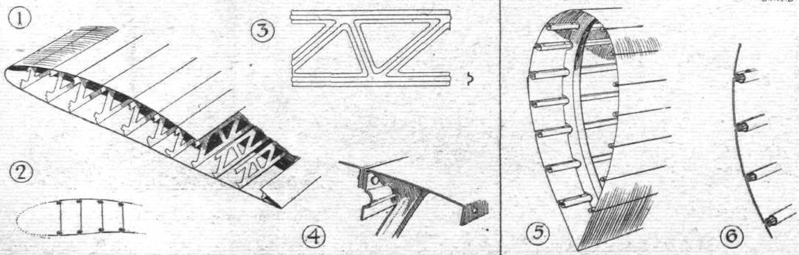
Very briefly explained, the fundamental principle upon which the designer of the Bernard type C-1 worked was to incorporate to as great extent as possible the outer covering as a stress-resisting part of the structure, and to adapt and simplify the internal framework accordingly. Thus one finds neither spars nor ribs in the ordinary sense of the terms, although members resembling, and performing the functions of, spars are employed in the wing structure. Similarly, in the fuselage the usual girder structure is absent, its place being taken by frames to which are attached the strips that form the covering or planking.
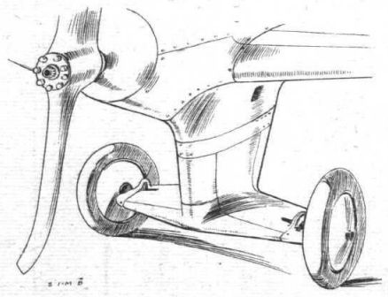
Dealing with the fuselage first, this is in section somewhat like a triangle with its corners rounded off, and its sides slightly curved. In other words, the sections are not unlike those of a sailing vessel, except that there are no hollows, but those occurring where the wings join the body. The frames are of box section Duralumin, and the covering strips, which are of shallow channel section, are riveted to the formers as well as to the U-section covering strips which bind together the flanges of adjoining channels. The fuselage is built up in three sections, the joints between which are covered by circumferential bands. The rear portion carries the tail, while the front portion, which is of heavy gauge Duralumin, serves as a main framework on which all the heavy stresses are concentrated, such as those from the undercarriage, wings, engine and pilot. This portion of the structure is in section somewhat like a cross, the base of which forms the undercarriage "leg," and the arms of which form the wing roots. Horizontally this cross extends forward to carry the engine and aft to support the pilot's seat.
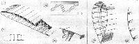
The wing structure is similar in principle to the fuselage, but with the exception that there are no ribs (which would correspond to the fuselage formers), whereas there are a considerable number of spars. The covering is similar to that of the fuselage, i.e., shallow channel section Duralumin strips having the flanges of adjoining channels riveted together, and to the edge of the spar's. The latter are stamped from the flat sheet, and have triangular lightening holes stamped in them, leaving top and bottom flanges braced by diagonal ties. In order to stiffen the spars, flanges as well as diagonal ties are fluted or corrugated. It is interesting to note that the spar edges are not placed between the flanges of adjoining channels, but on the side of them. Probably this has been done in order to get the spar edge away from the plane of maximum stress, and so get the latter taken chiefly by the portion of the channels which is bent over at a right angle. We frankly confess that we absolutely fail to guess in what way the last strip of wing covering or planking was got at for riveting. That it was done cannot, of course, be doubted, but it is difficult to see exactly how. It should be mentioned that the channel section strips of the wing covering are parallel, whereas those of the fuselage taper from maximum cross section to stern. An exception in the wings is formed by the strips at leading and trailing edges, which are slightly tapered. It is also of interest to note that the planking is of heavy gauge near the leading edge, gradually getting lighter as the trailing edge is approached, thus proportioning to some extent the thickness of the skin to the magnitude of the local stresses.
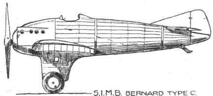
The undercarriage is of unusual' design, and time alone will show whether the inverted T-shape will stand up to rough landings. As exhibited, the machine had no radiators, and this fact helped in no small measure to give a clean outline. Ultimately we understand that two Lamblin radiators will be mounted, one on each side of the undercarriage "leg."
Designed by M. J. Hubert, the "Ferbois" type Bernard C-1 is a single-seater chaser with Hispano engine, and its characteristics are as follows :- Length, o.a., 6.6 m. (21 ft. 4 ins.); span, 10.2 m. (33 ft. 5 ins.); wing area, 17.2 sq. m (185 sq. ft.); weight, fully loaded, 1,200 kg. (2,640 lbs.). Unfortunately no figures are available of the structure weight of the machine. Engine 300 h.p. Hispano; power loading, 8.8 lbs./h.p.; wing loading, 14.3 lbs./sq. ft.; maximum speed (estimated), 315 km. (195 m.p.h.); ceiling, 6,000 m. (19,500 ft.).
Показать полностьюShow all
Flight, December 1926
The Paris Aero Show 1926
BERNARD (FERBOIS)
<...>
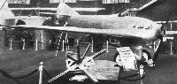
Whether inspired by the late arrival of the Armstrong Whitworth "Ajax" or through mere coincidence, one cannot say, but one morning several days after the opening of the Show, a new type of Bernard machine was suddenly discovered on this stand. This was a type 12.C.1 with Jupiter engine, and was of all-metal construction even to the covering, which was in general principle similar to the covering of an earlier single-seater shown by this firm at the 1924 Paris Show. This covering consists of sheet bent to channel sections, the flanges riveted internally to multiple spars. Certain changes were, however, to be noted in the way in which the width of these channels varied according to local requirements, doubtless with a view to facilitating construction. No particulars of this machine were available up to the time of our representatives' leaving the exhibition, but doubtless more will be heard of it in the future. Personally we prefer both the lines and the construction of the type 15.C.1.
Показать полностьюShow all