Barling NBL
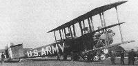
Хотя авиация Армии США, как и военная авиация других стран, после Первой мировой войны испытывала катастрофическую нехватку финансирования, некоторые попытки повысить ее боевой потенциал все же предпринимались. Командование определило, что существует потребность в стратегическом бомбардировщике - это привело к созданию XNBL-1 (опытный ночной бомбардировщик большой дальности, проект №1). Его проектировал Уолтер Барлинг из инженерного отдела управления авиации Армии США (Маккук-филд, штат Огайо), а строила его компания "Witteman-Lewis Aircraft Corporation" (Ньюарк, штат Нью-Джерси).
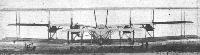
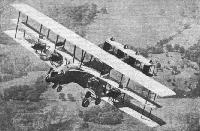
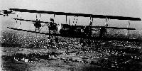
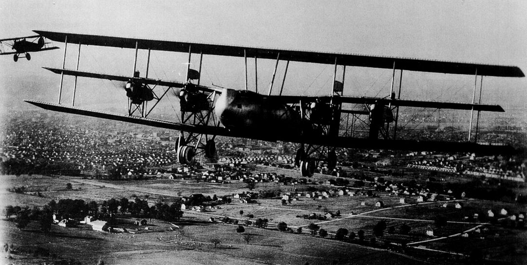
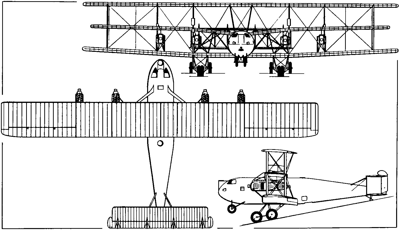
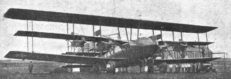
Когда XNBL-1 впервые поднялся 22 августа 1923 года в воздух, он стал самым большим самолетом в мире. Схема - триплан, коробка крыла имела размах 36,58 м, при этом среднее крыло имело уменьшенные размах и хорду. Массивный фюзеляж нес в задней части бипланное хвостовое оперение с четырьмя килями и рулями направления, кили служили также межкрыльевыми стойками бипланных горизонтальных хвостовых элементов. Угол атаки указанных поверхностей мог регулироваться в полете, всем хвостовым оперением пилот управлял из кабины. Хвостовой костыль также отличался необычной конструкцией, каждая стойка главного шасси имела четыре колеса, еще два колеса установили под носовой частью фюзеляжа, чтобы предотвратить самолет от удара носом о землю при посадке на неподготовленных аэродромах. Передняя пара колес каждой главной стойки при заходе на посадку могла несколько вытягиваться, касание земли сначала происходило этими четырьмя колесами, а затем, с падением скорости, также и задними основными колесами и хвостовым костылем. Два пилота располагались бок о бок в открытой кабине, управление было двойное. Пять других мест для экипажа давали возможность размещать до семи пулеметов, обеспечивавших активную оборону против любого возможного противника.
Слабым местом XNBL-1 являлась силовая установка из шести двигателей Liberty, они устанавливались между нижним и средним крыльями. Внутренние установки представляли собой пары двигателей, состыкованных задними сторонами и приводивших в действие тянущий и толкающий винты. Полная мощность данной силовой установки совершенно не соответствовала общей массе самолета, и, как следствие, характеристики бомбардировщика были неудовлетворительными по скорости, полезной нагрузке и длительности пребывания в воздухе. Разочарование вызвало и то, что "бомбардировщик Барлинга" не смог перелететь горы Аппалачи во время полета из Дейтона в Вашингтон. Из-за отсутствия финансирования в 1925 году дальнейшую разработку бомбардировщика прекратили, на планировавшееся создание XNBL-2 денег не выделили. XNBL-1 на многие годы оказался первым и единственным "гигантским" аэропланом американской авиации.
ТАКТИКО-ТЕХНИЧЕСКИЕ ХАРАКТЕРИСТИКИ
Barling XNBL-1
Тип: семиместный опытный дальний бомбардировщик
Силовая установка: шесть V-образных двигателей Liberty 12А, каждый мощностью 420 л. с. (313 кВт)
Характеристики: максимальная скорость на оптимальной высоте 154 км/ч; крейсерская скорость 98 км/ч; практический потолок 2355 м; дальность полета с бомбовой нагрузкой 2268 кг - 274 км
Масса: пустого 12 566 кг; максимальная взлетная 19 309 кг
Размеры: размах крыла 36,58 м; длина 19,81 м; высота 8,23 м; площадь крыльев 390,18 м'
Вооружение: семь наводимых 7,62-мм пулеметов и до 2268 кг бомб
Показать полностьюShow all
Flight, December 1923
THE BARLING BOMBER
An American Six-Engined Giant
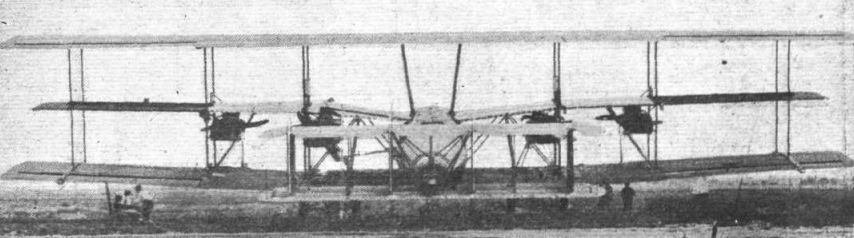
WHAT is described as the world's largest aeroplane was constructed and tested at the U.S. Army Air Service Depot, Wilbur Wright Field, Dayton, during last summer. This machine is officially designated the N.B.L.-1, but is perhaps better known as the Barling Bomber, after its designer, Walter H. Barling, who was, we believe, associated with the Tarrant "Tabor" triplane built in this country in 1919. N.B.L.-1 was built by the Wittemann Aircraft Corporation.
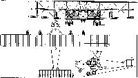
The Barling bomber is a triplane - or, as may be seen from the accompanying illustrations, a two-and-a-half plane, as the middle plane is of comparatively narrow chord. The overall span of the main planes is 120 ft. and their chord 13 ft. 6 ins., whilst the span and chord of the middle plane are 111 ft. and 10 ft. respectively. It is fitted with six Liberty engines, mounted on the wings just below the middle wings, two arranged in tandem on each side and nearest to the fuselage, and the remaining two singly farther out towards the tips.
The materials used throughout the ship are of the "safety first" type. The basic material is spruce, which is more reliable than other aircraft material. Nearly all the main fittings are of 60,000 lb. steel, and duralumin is used for pulley brackets and other parts coming under relatively low stresses. Bakelite pulleys, with ball bearings, are used throughout the controls.
It is claimed for the arrangement of the main planes that the combined advantages of biplane and triplane systems are obtained. For instance, whilst the triplane arrangement provides a smaller span, the reduced middle plane lessens the overall height of usual triplane construction and thus ensures safer taxying and landing. Again, the erection of the machine is easier than would be the case of a large-gap biplane, and the engine support is improved by this triplane construction.
As will be seen, all three planes are in three sections, an inner one including fuselage, landing gear, and the two pairs of tandem engines; and two outer sections, each carrying one of the two remaining engines. Two pairs of interplane struts separate the planes of the centre section on each side of the fuselage, and a further two pairs of struts support the centre of the top plane above the fuselage. Ailerons are fitted to the top and bottom planes only, and there is thus little or no interference with the narrow chord middle plane. The lower plane is set at a dihedral angle of about 3°.
The six 400 h.p. Liberty engines are mounted in four nacelles, two on each side of the fuselage between the lower and the mid planes. They are placed sufficiently far apart that, should it be desired to lit larger engines at any time, there is sufficient space for 18-ft. air screws to be fitted. In the two nacelles nearest the fuselage two engines are placed in tandem end to end, the front ones driving tractor screws, and the rear ones pusher screws. Each of the two outer nacelles has a single engine driving a tractor screw.
As the loads on this machine are large, and frequent change of pilots would be necessary on long flights, dual control sets are provided for two pilots, sitting side by side. A control lever in the pilot's cockpit regulates the operation of the engines, a forward movement of this lever opening the throttles of all six engines, and a backward movement closing them. A lateral movement of the lever opens the throttles of the engines on that particular side only, whilst by a diagonal movement of the lever the engines on one side are partially throttled, while those on the other side are kept open.
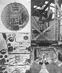
The pilot's instrument-board is naturally somewhat elaborate, as may be seen from one of our illustrations. There are six engine revolution indicators, three on each side, an air-speed indicator, a turn indicator which gyroscopically indicates any rotating motion about a vertical axis, an altimeter, clock, etc. The engineer's controls are arranged in two banks, those for the three port engines being to the left, and those for the starboard engines being on the right. Each engine has a throttle, mixture, ignition, and shutter control. The latter provides a micrometer adjustment, and has emergency clutches, so that any engine may be used in case of damage, independent of the other engines or the master control.
The fuselage, which is built in sections, is of the semi-monocoque type, the outer covering of veneer being strengthened by longerons and bulkheads. One of the accompanying illustrations, showing the interior of the fuselage, will give a general idea of the form of construction employed. It is stated that there are no vital longerons or wires, which if shot away would place the machine out of action. The fuselage has a maximum diameter of 10 ft., and is of circular section of good streamline form. Provision is made for seven guns, which are operated from five cockpits, so located that they cover practically the whole field of approach. One of these gun positions is located in the extreme nose of the fuselage, with another one immediately underneath it, firing below the fuselage. Two others are situated back of the main planes, one at the top and one at the bottom of the fuselage.
The bomber's compartment is shown in one of our illustrations, from which it will be seen that the bomber sits on a bicycle-saddle type seat and operates the bomb sight mounted over a window in the floor. The bomb-release levers may be seen on the right, and the various instruments on the left. The bomb crates are below the petrol tanks, and in the bottom of the fuselage are trap doors enabling the bombs to fall freely when released. A walkway on each side gives free access to any part of the machine.
The tail is a biplane structure, with an adjustable incidence, controlled from the cockpit, a special thin wing section being employed. There are four rudders and fins, similar in size and shape, the fins also serving as interplane struts. Owing to the size of the tail planes, the problem of providing for adjustable stabilisers presented some difficulty, for it may be noted that the overall span of the tail is some 45 ft., and the combined areas of the stabilisers and elevators is 575 sq. ft.; the fins and rudders have an area of 250 sq. ft. Except for the ribs and covering, the tail surfaces are of metal construction.
Not the least interesting feature of the Barling bomber is the landing gear, which in a machine of this size naturally presents many unusual problems. The Barling landing gear consists of two four-wheeled "trucks," one under each of the inner engine groups, all four wheels being 60-in. by 12-in. Palmer aero type. Each truck has two wheels close together on the front axle and two on the rear axle. On landing, means is provided for lowering, from the pilot's cockpit, the front wheels, so that these come into contact with the ground first, the energy of landing being absorbed by means of long-stroke oil cylinders. The rear wheels, which are sprung by rubber shock absorbers of the endless ring type, then come into action, and the machine settles down on these wheels and the tail skid. Taxying is done on the rear wheels. A pair of emergency wheels mounted on the nose of the fuselage prevent the machine from digging in."
The tail skid is also an interesting feature. This is of all-metal construction, the skid proper being an aluminium alloy "boat," armoured with steel straps and having a steel keel. This "boat" swivels on a support attached to a cross axle, which is prevented from motion by means of rubber cords.
As regards the performance of the N.B.L.-1, with full capacity of petrol (2,000 gals, or 6 tons) and oil (181 gals, or 1,356 lbs.), it is capable of flying at full speed, 90 m.p.h., for a duration of about 12 hours. The minimum crew necessary to operate the machine consists of four men. Specifications require a maximum of 5,000 lbs. of bombs to be carried, but it will be possible to carry a 10,000-lb. bomb, for a duration flight of 2 hours. The total weight of this machine, fully loaded, comes out at about 40,000 lbs. (18 tons).
The Barling bomber made its maiden flight, lasting 28 minutes, on August 22 last, at Wilbur Wright Field. This flight was successful in every way, surpassing the expectations of its designer and the U.S. Air Service. The ease with which it manoeuvred, both on the ground and in the air, the 10-second take-off and its 60 m.p.h. landing were the outstanding features. The altitude attained on this occasion was 2,500 ft.
The principal characteristics of the N.B.L.-1 are as follows :-
Overall span 120 ft.
Overall length 65 ft.
Overall height 27 ft. 9 ins.
Chord 13 ft. 6 ins.
Area of main planes (approx.) 4,180 sq.ft.
Area of stabilisers and elevators 575 sq. ft.
Area of fins and rudders 250 sq. ft.
Weight loaded 40,000 lbs.
Loading per h.p. (approx.) 16-5 lbs.
Loading per sq. ft. (approx.) 9-5 lbs.
Petrol capacity 13,440 lbs. (2,000 gals.)
Oil capacity 1,356 lbs. (181 gals.)
Speed range 60-90 m.p.h.
Показать полностьюShow all

 Wiki
Wiki