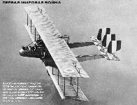
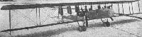
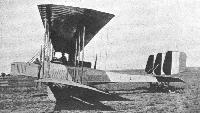
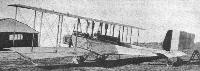
Caproni Са 1, Са 2, Са 3 и Са 5
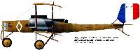
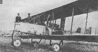
Кроме России, только в Италии еще до Первой мировой войны начали разрабатывать многомоторные бомбардировщики. Спроектированный в 1913 году, Caproni 260 hp (Са 31) впервые взлетел в октябре 1914 года с силовой установкой из трех ротативных моторов Gnome. Это был большой двухфюзеляжный трехстоечный биплан цельнодеревянной конструкции. Один мотор, установленный сзади в центральной гондоле, приводил в действие толкающий воздушный винт, остальные два мотора вращали тянущие винты в носовых частях фюзеляжей.
Из-за недостаточной мощности моторов Са 31 мог летать с большим трудом. Его концепцию повторили в новом прототипе Caproni 300 hp (позже ретроспективно обозначенном Са 32) с двумя рядными двигателями Fiat А.10 увеличенной до 100 л.с. (75 кВт) мощности, установленными в носовых частях фюзеляжей, и одним таким же - в задней части переделанной центральной гондолы. Также переделали крылья и хвостовое оперение.
После постройки двух прототипов итальянские военные заказали серийное производство машины под обозначением Са 1. С августа 1915 до декабря 1916 года было поставлено около 160 таких самолетов.
По завершении войны несколько уцелевших машин переделали в гражданские транспортно-пассажирские самолеты Са 56, пригодные для перевозки шести пассажиров.
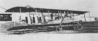
Развитием концепции стал самолет Са 2 (обозначение разработчика Са 350 hp), построенный в количестве девяти экземпляров. Он отличался от Са 1 центральным мотором Isotta-Fraschini V.4B мощностью 150 л.с. (112 кВт). В ходе боев стало ясно, что планер сконструирован удачно, но мощность силовой установки требует дальнейшего повышения.
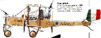
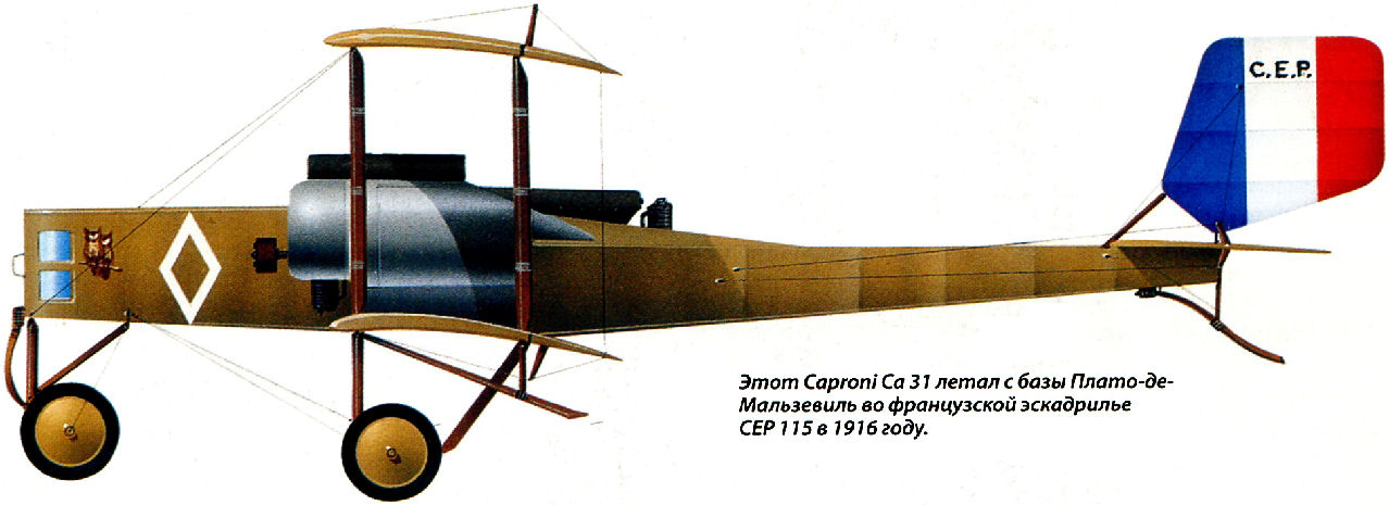
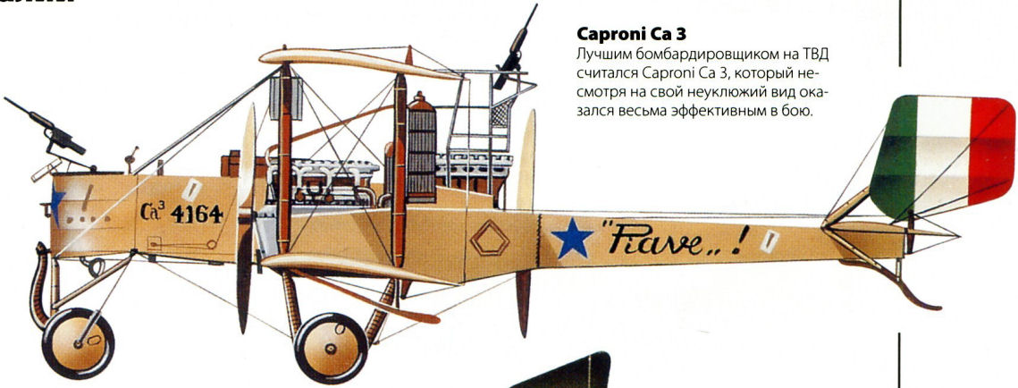
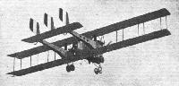
Пришлось создать Са 3 - версию Са 2 с повышенной энерговооруженностью. Все три его мотора были Isotta-Fraschini V.4B мощностью no 150 л.с. Прототип испытали в конце 1916 года и запустили в серию под заводским обозначением Caproni 450 hp (позднее Са 33). С февраля 1917 года по 1919 год армии было поставлено 298 таких самолетов, которые служили в основном в качестве тяжелых бомбардировщиков, а также ограниченно использовались итальянским ВМФ в роли торпедоносцев. Несколько бомбардировщиков было поставлено во Францию, где еще 83 такие машины были построены по лицензии фирмой Роберта Эно-Пельтри под обозначением Caproni-Esnault-Pelterie.
После войны несколько доживших до ее окончания самолетов переделали в шестиместные пассажирские машины Са 56а.
Вариант Са 3 mod (modificato - измененный) был известен на фирме "Caproni" как Са 36 (иногда Са 36М) - улучшенная и упрощенная версия Са 3. С 1923 по 1927 годы было поставлено 153 самолета. Бомбардировщики Са 3 mod участвовали в колониальной войне фашистского режима Муссолини в Северной Африке.
Позднее несколько Са 3 mod переделали в санитарный самолет Са 36S и в другие варианты, не вышедшие за стадию проектов или опытных образцов, например, Са 34 и Са 35 с тандемной кабиной пилотов, Са 36 со съемными консолями крыльев, двухместный штурмовик Са 37 и гидросамолет Са 39 с поплавковым шасси.
К 1917 году фирма "Caproni" пришла к заключению, что характеристики бомбардировщиков бипланов Са 3 и трипланов Са 4 недостаточны для успешного проникновения во вражеское воздушное пространство, защищенное современными истребителями.
Так появился бомбардировщик бипланной схемы, обозначенный фирмой-изготовителем как Caproni 600 hp или 600/900 hp (серия Са 44), а итальянскими военными - индексом Са 5. Его строили в двух подмодификациях, обозначенных фирмой-изготовителем как Caproni 750 hp, или 600/750 hp (Са 45), и Caproni 900/1200 hp (Са 46). С 1918 по 1921 год было изготовлено 659 самолетов этих моделей.
По общей концепции Caproni 600 hp был модифицированным Caproni 450 hp (Са 3) с силовой установкой повышенной мощности, новыми крыльями, более аэродинамичной центральной гондолой и переделанным шасси.
Прототип Caproni 600 hp впервые взлетел во второй половине 1917 года с силовой установкой из трех рядных двигателей Fiat А.12 мощностью по 200 л.с. (149 кВт), позже замененных на три улучшенных двигателя А.12 мощностью по 250 л.с. (186 кВт). Была заказана огромная серия из 3900 самолетов, позже уменьшенная до 3650 машин, одна треть которых предназначалась для службы во Франции, однако в связи с окончанием войны построено было гораздо меньше.
К запланированному производству еще 1500 самолетов для США привлекли две французские и две американские фирмы. Но окончание воины привело к радикальному сокращению всех заказов. Фактически французских самолетов не сделали ни одного, американских - всего три (две машины Са 44 на фирме "Standard" и одна Са 46 на фирме "Fisher"), французы, американцы и итальянцы применяли в боях только Са 5 итальянского изготовления.
Са 44 оснащался тремя моторами А.12 или A.12bis мощностью по 250 или 300 л.с. (186 или 224 кВт). Он был основным серийным образцом в 1917 году.
Позднее Са 44 переделали в выбранный Францией вариант Са 45 с силовой установкой из трех двигателей Isotta-Fraschini мощностью по 250 л.с. (186 кВт). Са 46, разработанный в 1918 году, обладал уменьшенной дальностью, но увеличенной максимальной бомбовой нагрузкой благодаря силовой установке из трех V-образных поршневых двигателей Liberty 12 мощностью по 360 л.с. (269 кВт).
Несколько бомбардировщиков Са 44 переделали в санитарные самолеты Са 50 с оборудованием для установки носилок в контейнерах-обтекателях под фюзеляжами. По завершении мировой войны несколько Са 44 и Са 45 переоборудовали в пассажирские самолеты Са 57 (другое название Breda М-1) с салонами на восемь пассажиров.
Еще 10 Са 44 переделали в гидросамолеты I.Ca, также известные под обозначением Са 47.
ТАКТИКО-ТЕХНИЧЕСКИЕ ХАРАКТЕРИСТИКИ
Caproni Са 3
Тип: тяжелый бомбардировщик с экипажем из четырех человек
Силовая установка: три рядных двигателя Isotta-Fraschini V.4B мощностью по 150 л.с. (112 кВт)
Летные характеристики: максимальная скорость 140 км/ч на уровне моря; набор высоты 4000 м за 40 мин; практический потолок 4800 м; дальность полета 450 км; время полета 3 ч 30 мин
Масса: пустого 2300 кг; максимальная взлетная 2890 кг
Размеры: размах крыла 22,20 м; длина 10,90 м; высота 3,70 м; площадь крыла 95,64 м!
Вооружение: один подвижный стреляющий вперед 6,5-мм пулемет Revelli в носовой установке, и один, два или три подвижных стреляющих назад 6,5-мм пулемета Revelli в надфюзеляжной установке, плюс до 450 кг бомб на внешней подвеске.
Показать полностьюShow all
Flight, April 1920
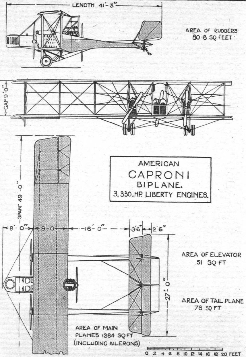
THE AMERICAN-BUILT CAPRONI BIPLANE
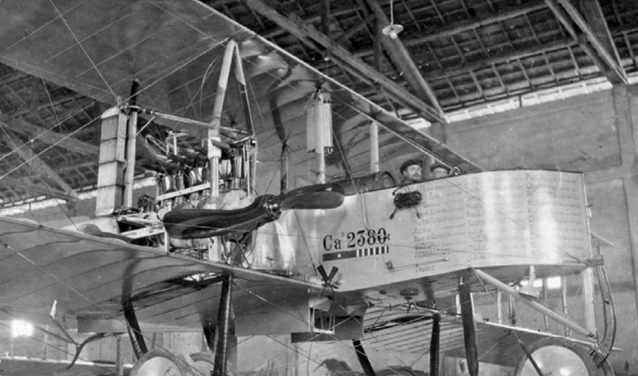
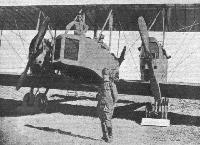
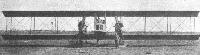
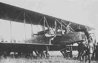
THE Italian Caproni biplane, which was developed during the War, and played a by no means small part in same, was from the first unique on account of its original design, viz., in having two fuselages and a nacelle, each with its own power plant. Not entirely original, perhaps, as regards twin fuselages, for the French Nieuport firm brought out an experimental monoplane having two fuselages, but it was a single-engined machine, and the fuselages merely served as outriggers for the tail. In the Caproni biplanes, which have changed only as regards types of engines and minor details since the first one was laid down in 1915, the two fuselages not only carry the tail but carry in the nose of each an engine driving a tractor screw, whilst between the fuselages is a nacelle carrying the crew and, at the rear, a third engine driving a pusher screw.
The Caproni was one of several types of Allied machines which were to be manufactured in America for use in the theatre of war, and at the time of the Armistice everything was ready for the mass production of the Caproni biplane. Several were, as a matter of fact, constructed, and the accompanying illustrations and data refer to a machine manufactured by the Standard Aircraft Corporation of Elizabeth, N.J. The American Caproni differs from its Italian prototype only in minor details, the general design being identical. It is equipped with three low-compression Liberty engines of 330 h.p. each, which being more powerful than previous power plants necessitated an increase in some of the dimensions, and to make quantity production possible, special materials and parts were systematically eliminated and replaced with parts and materials of American standard types and qualities.
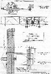
The main planes are built up in five sections, corresponding sections in upper and lower planes being of equal length. The centre section, which measures some 16 ft., carries, on the lower panel, the central nacelle, the two fuselages and the undercarriage, and thus forms a main self-contained unit capable of easy transport within a minimum of space. The intermediate and outer extensions, which measure about 18 ft. 6 ins. and 13 ft. respectively, also take up little space, and are fitted to each other and the centre section by means of male and female box fittings and pins. A modification of the Eiffel No. 36 wing section is employed, the camber of the under curve being 3-267 ins. and that of the upper curve 7-618 ins., and the maximum ordinates occurring 31-496 ins. and 39-37 ins. respectively from the leading edge. The maximum thickness ot the section is 4-665 ins., occurring 55-118 ins. from the leading edge. The main spars are of the box type, the centre section and the intermediate upper plane section spars being of ash, and all others of spruce or Douglas fir. They are wrapped with fabric between ribs and measure 19/32 ins. by 3 5/8 ins. All the ribs, double ribs and box ribs are of white wood and ash, and the capstrip is screwed in position and not nailed.
There are altogether nine bays in the complete wing structure, disposed three for the centre section, two for each intermediate and one for each outer section. All incidence wires are No. 10 steel wire, except in the centre section, where 5/32 in. cable is employed, and all lift cables are doubled except in the outer section. The landing cables are single. All the cables are spliced and not soldered, and the tumbuckles are located at the bottom of the struts and are received directly by socket terminals. Two drift wires run from the nose of the nacelle to the tops and bottoms of the front inner intermediate section struts.
With the exception of some of the centre section struts the interplane struts are of stream-line section steel tubing, or round-section steel tubing streamlined with spruce fairings. The strut sockets are all of the same general design, but are not interchangeable, being made heavier towards the centre of the machine to meet the increased stresses, as is also the case with the interplane struts. These strut sockets consist of two steel plates welded to the fore and aft sides of a square steel sleeve, which is slipped over the outside ends of the spars and secured to the latter by three 1/4-in. bolts. Three lugs formed on the steel plates project beyond the spar, the central lugs receiving the interplane strut - a bolt passing through lugs and strut - and the outer lugs carrying bolts which serve as anchorages for the turnbuckles and cable ends of the interplane bracing. The internal bracing of the wings is, as usual, of cables and tie-rods. The covering is Grade A linen nailed on the cap-strips and edges, with maple batten strips screwed above the linen corresponding to the ribs.
The tail consists of a high aspect ratio horizontal stabiliser, a one-piece elevator, and three balanced rudders mounted above the latter. The horizontal stabiliser is provided with a positive incidence change gear. All the tail surfaces are of steel construction (spruce also being employed in the case of the rudders), the ribs of the horizontal stabiliser being made from pressed sheet steel. The stabiliser is secured to the fuselages by means of steel tubes, faired with laminated spruce, two extending from the bottom of each tail post outward to the front and rear spars of the stabiliser, and two extending inwards, also to the front and rear spars. The rudders are held in place by means of steel posts, trussed together by wire, the two outer rudder posts working in the fuselage stern posts, whilst the central rudder post engages with a socket brazed on the rear spar of the stabiliser. A pair of stream-lined steel-spruce struts extend from the front spar of the stabilizer - at points where the inner bracing struts from the fuselages, are attached - to a point half-way up on the central rudder post. All levers are of stamped steel strut, and are easily removed ; only the outer rudders have levers. The control cables are carried on bronze pulleys fitted with ball bearings, and are doubled.
The central nacelle is built up of two laminated spruce longerons, and former ribs giving a good stream-line shape, and an outer covering of 5/32 in. three-ply. It is secured to the lower wing spars by four ash struts, and four other struts extend, in continuation, upwards to the top plane. At the forward end of the nacelle is a cockpit with revolving gun-ring for the front gunner and observer, whilst immediately behind is the pilot's cockpit, providing accommodation for two, seated side by side. Dual control is provided, and in front of the pilots is a large dash on which are mounted the various instruments. Ignition, petrol and altitude adjustment are controlled for the three engines from a board located between the two pilots. The bomb-sighting device, bomb release gear, camera, radiator shutters, and the lighting and heating, are all controlled from the pilots' seats. Immediately behind the pilots' seats are two large petrol tanks, and behind these, between front and rear wing spars, is a compartment containing the bomb rack and rear gunner. The engine is supported on its bed by three braces of bass-wood, ash and ply-wood. In the nose of the nacelle axe two radiators, with shutters, for the central engine, but the oil tank and oil radiator are mounted near the latter itself. The overall length of the nacelle is 19 ft. 10 ins., and the maximum width and depth 4 ft. and 5 ft. 6 ins. respectively.
The two fuselages, which are identical, are built up of four ash longerons, 3/16 in. square, channeled on the vertical sides between the struts from the fifth bay to the stern post, there being 12 bays in all. The top longerons have one, and the lower longerons two lap splices, about 12 ins. long, glued, screwed and wrapped with fabric. The first two vertical struts are of 1 3/16 in. steel tubing, and the corresponding lower lateral struts are of ash, all other struts being of spruce; the stern post is of steel tube. The whole fuselage is braced with steel wire. The tops of the fuselages consist of a turtle back, built up of spruce strips, secured to walnut arches with small screws. From the nose to the rear spars the covering is sheet aluminium, thence to the sternpost, the covering is fabric. The engine, with front radiators, is mounted in the nose of the fuselage. The fuselages are secured to the lower plane by U-bolts which pass over the bottom lateral struts and over the wing spars and through steel plates on the under side of the spars. Most of the fittings in the fuselages are of sheet steel, designed to avoid bolts passing through the longerons.
The undercarriage consists of two U-struts of laminated ash and spruce., wrapped with fabric and braced with steel tubing. One U-strut is located under each fuselage, and each axle carries two rubber sprung double wheels, the axles of which are 1 5/16 in. diam. by 5/32 in. thick steel tubes, kept in position by radius rods ending at the extremities in a universal joint which has its seat on the same fitting on which the main bracing cables of the chassis end.
As previously stated, the power plant consists of three Liberty 12 engines, low-compression, of 330 h.p. each. The engines are inclined at an angle of 20, and the tractor and pusher screws are 9 ft. 6 ins. diameter by 6 ft. 6 ins. pitch. Petrol is disposed in six tanks, two in the nacelle and two in each fuselage. Each tank is divided into compartments, at the bottom of which check valves are fitted, thus preventing loss of petrol should any of the compartments be pierced. Petrol is drawn from the main tanks by windmill pumps mounted on the chassis struts, and forced, via a central distributor in the pilots' cockpit, to gravity tanks mounted on the interplane struts.
A storage battery and wind-driven generator (600 Watts) combination supplies current for lighting.
The general characteristics of the American-built Caproni biplane are as follows :-
Span (both planes) 49 ft. 0 ins.
Chord 9 ft. 0 ins.
Gap 9 ft. 0 ins.
Overall length 41 ft. 3 ins.
Overall height 14 ft. 8 ins.
Angle of incidence 5° 30
Wing section Modified Eiffel 36
Area of main planes (including ailerons) 1,384 sq. ft.
Area.of tail plane 78 sq. ft.
Area of elevator 51 sq. ft.
Area of rudders (3) 80-8 sq. ft.
Area of ailerons (4) 160 sq. ft.
Gross weight fully loaded 12,931 lbs.
Disposed as follows :-
Power plant 4,446 lbs.
Fuel and oil 2,700 lbs.
Passengers, equipment and instruments 695 lbs.
Armament and bombing equipment 1,581 lbs.
Wing structure 1,631 lbs.
Tail and bracing 220 lbs.
Nacelle and fuselages 938 lbs.
Undercarriage 350 lbs.
Useful load 2,546 lbs.
Loading per sq. ft. 9-3 lbs.
Loading per h.p. 13 lbs.
Speed (ground level) 105 m.p.h.
Climb to 6,500 ft. 11 mins.
Climb to 15,000 ft. 1 hr. 10 min.
Показать полностьюShow all


 Wiki
Wiki