Fokker (America) F.32
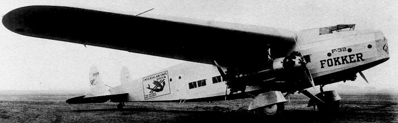
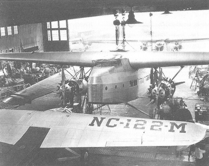
Четырехмоторный транспортно-пассажирский самолет F.32 стал последним проектом фирмы "Fokker", строившимся в США. Его появление в 1929 году вызвало большой интерес. Число 32 в обозначении указывало на его пассажировместимость, но в ночных полетах число пассажиров уменьшалась вдвое - до 16 спальных мест.
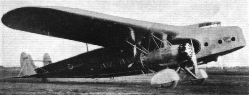
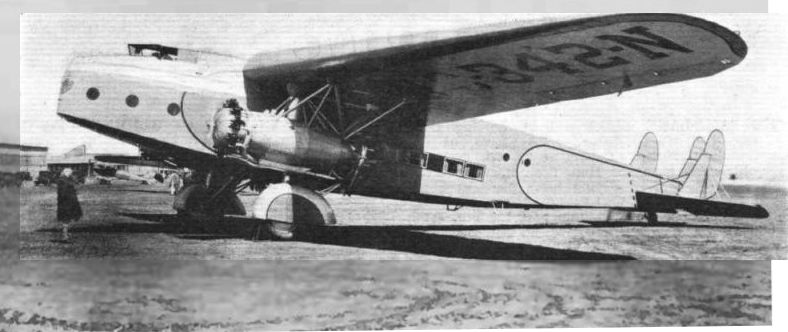
F.32 был большим свободнонесущим высокопланом с короткой носовой частью. Его неубирающееся ширококолейное шасси имело обтекатели колес. Кабина экипажа была сильно смещена вперед от передней кромки крыла, пассажирский салон располагался под крылом и в хвостовой части фюзеляжа. Силовая установка состояла из четырех звездообразных моторов Pratt & Whitney Hornet, установленных парами тандемно в двух моторамах под крылом. Два мотора были тянущими, другие два - толкающими.
Серийно изготовили до 10 самолетов F.32. В 1930 году несколько таких машин попали на службу в калифорнийскую авиакомпанию "Western Air Express". Вскоре возникли проблемы с охлаждением толкающих моторов. Их так и не удалось разрешить полностью, так что активная карьера самолета F.32 оказалась относительно короткой. Одна из этих машин оценивалась авиакорпусом Армии США под обозначением YC-20, но не получила армейский серийный номер и не была закуплена.
ТАКТИКО-ТЕХНИЧЕСКИЕ ХАРАКТЕРИСТИКИ
Fokker F.32
Тип: пассажирский самолет с экипажем из пяти человек
Силовая установка: четыре звездообразных ПД Pratt & Whitney Hornet B мощностью по 575 л. с. (429 кВт)
Летные характеристики: максимальная скорость 225 км/ч на оптимальной высоте; крейсерская скорость 198 км/ч на оптимальной высоте; начальная скороподъемность 305 м/мин; практический потолок 4115 м; радиус действия 1191 км
Масса: пустого 6840 кг; максимальная взлетная 11000 кг
Размеры: размах крыла 30,18 м; длина 21,29 м; высота 5,03 м; площадь крыла 125,42 м2
Полезная нагрузка: до 32 пассажиров на дневных рейсах либо до 16 на ночных (в пределах 2554 кг максимальной нагрузки)
Показать полностьюShow all
Flight, April 1931
THE FOKKER F.32
A four-engined commercial monoplane produced to meet the demand for a machine carrying thirty passengers on busy air routes. Such a demand was felt in America, existing 8-16 passenger machines being unable to cope with increased traffic, and as a result, the Fokker Aircraft Corporation of America produced the F. 32 described below
BRIEF reference was made in FLIGHT a short while ago to the Fokker F.32 four-engine monoplane, which is employed on certain air lines in America, and which will probably be used on the Dutch East Indies service. This week we are able to give a description of this machine from information supplied by the Fokker Co., of Amsterdam.
As with the majority of Fokker commercial machines, the F.32 is a cantilever monoplane, and has four engines - 575 h.p. Pratt & Whitney "Hornet B" - mounted tandem-wise in pairs under the wings on each side of the fuselage.
The wing consists of 2 box spars with section-shaped ribs slid on to them. These spars measure 43-31/32 in. (1.10 m.) front and 34-33/64 in. (0.87 m.) deep at the centre. The leading edge has a sweep back of 56 in. (1.42 m.), and the under surface has a negative dihedral of 3 1/2°. The leading edge of the centre section is cut away, and the roof of the cockpit made flush with the wing's upper surface. The wing is covered with plywood.
The wing is secured by means of four bolts, to joints in the framework of the fuselage. Four fuel tanks are installed between the spars, two on either side of the fuselage.
As is customary in Fokker aircraft, the fuselage is made up of a framework of seamless cold drawn steel tubes autogenously welded together and braced by means of steel wire and tubular diagonals. Under the cabin the framework is further stiffened by corrugated dural, on which the plywood floor (3/16 in.) is laid. A fuselage tail piece is used to fair the end of the fuselage and made detachable in order to facilitate inspecting of the interior of the fuselage.
In the nose of the machine is the luggage hold, which extends under the cockpit and has a cubic capacity of 120 cu. ft. (3.4 m.3). The walls of this compartment are lined to a height of 30 in. (75 cm.) with sheet aluminium. Two windows, 8? in. (22 cm.) in diameter, located one on either side, furnish the daylight.
A trap-door, 27 in. (69 cm.) wide by 40-5/16 in. long (1.03 cm.), in the lower wall gives access to the cockpit and luggage hold. When open this door extends into a ladder, having ten steps from the ground to the cockpit.
The amount of space available for radio installation is 3.4 in. (1.20 m.) long, 3.9 in. (1.14 m.) high, and 7 ft. (2.13 m.) wide, extending under the cockpit from one side of the plane to the other. On either side there is a round window 8 1/2 in. (22 cm.) in diameter.
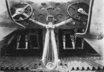
The cockpit is immediately to the rear of and partly over the luggage hold. The pilots' seats are placed well forward, and the window has an inwardly slanted V front of 110° included angle. Each section of the V contains a sliding window, while the windows in the side walls are also made sliding. The top of the cockpit, made of domed sheet aluminium, is flush with the upper surface of the wing. Green celluloid windows are fitted in the aluminium roofing for upward visibility.
The instruments are mounted within easy reach of the pilots. On the left of the main instrument board, in front of the pilots, are the compass, the air-speed indicator, the altimeter, rate of climb indicator, the gyroscopic bank and turn indicator, a transversal inclinometer, and, further, the switches for the navigation lights. In the middle of the board are the tachometers for the four engines, the four throttle levers (the centre two operating the rear engines and the outer ones the front engine throttles) and the master cutout switch. The independent ignition switches are mounted on a board under the throttle levers. On the right-hand side of the main instrument board are mounted the oil pressure and temperature indicators for the four engines.
Centrally located behind the pilots there is a second instrument board containing the mixture controls, spark controls, starter switches and vibrating coil switches (which take the place of starter magnetos) (see next page), and further the handles for operating the fuel taps. On the right-hand side of this board are the right flare release, controls for the right engine's nose cowling, and for the right oil tank vent. Similar controls are mounted on the opposite side for the left-hand engines, etc.
To the left of the second pilot, and immediately under this board, are the switches for the cabin lights and fuse panels.
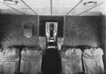
As a day transport, provision is made for 30 passenger seats, arranged in four compartments. As a night sleeper, the cabin is transformed into eight sections, accommodating 16 births, 8 upper and 8 lower. Any combination of passenger, mail and goods can be worked out to suit any particular commercial demands or private owner.
When fitted out for 30 passengers, the cabin space is divided as follows :- Forward compartment, directly behind pilot's cockpit, 6 ft. 0 1/2 in. (1.84 m.) long, 7 ft. 7 in. (2.31 m.) wide, and 5 ft. 9 in. (1.75 m.) high, having a capacity of 263 cu. ft. (7.44 cu. m.). To the rear of this is a second compartment, 6 ft. 11 in, (2.11 m.) long, 8 ft. 10 in. (2.69 m.) wide, and 7 ft. 5 in. (2.26 in.), with a capacity of 453 cu. ft. (12.83 cu. m.). Then follows on either side of the gangway (2 ft. 1 in. wide and 5 ft. 10 in. high) a galley measuring 2 ft. 6 in. (0.76 m.) long, with a space between the gangway and the side of the plane of 3 ft. 4 in. (1.02 m.) and a height of 8 ft. 6 in. (2.59 m.). Each galley has a capacity of 71 cu. ft. (2 cu. m.) and daylight is furnished through a window 8 1/2 in. diameter in either side of the fuselage, and two windows in the ceiling.
The third compartment, located immediately behind the galley, measures 6 ft. 8 in. (2.03 m.) long, 8 ft. 7 in. (2.62 m.) wide, and 8 ft. 1 in. (2.46 m.) high, and has a capacity of 460 cu. ft. (13.03 cu. m.). Directly behind this is the last compartment. 6 ft. 8 in. (2.03 m.) long, 8 ft. 3 in. (2.51 m.) wide and 7 ft. 8? in. (2.35 m.) high; capacity, 423 cu. ft. (11.97 cu. m.). The total space available for passengers is therefore 1,598 cu. ft. (45.27 cu. m.).
Behind the last compartment, and running across the plane, is the entrance compartment, 2 ft. 6 in. (0.76 m.) long, 8 ft. 2 in. (2.49 m.) wide, and 6 ft. 11 in. (2.12 m.) high. There are two aluminium frame doors, one on each side, 2 ft. 6 in. wide and 4 ft. 9 in. high, each having an 8-in. diameter window. Behind this entrance passage are two lavatories, 2 ft. 10 in. long, 3 ft. 9 1/2 in. wide and 6 ft. 6 1/2 in. high.
The cabin has 16 windows, 26 in. x 16 in., of 3/16 in. non-shatterable glass. Good ventilation is provided by means of 18 "S" type ventilators, each having a throat diameter of 7/8 in. These are so arranged that, by turning them, either suction of cabin air or pressure of outside air into the cabin can be regulated. Twelve dome lamps provide the lighting for the cabin.
The nose tip of the fuselage, the upper surface up to the cockpit, the roof and sides of the cockpit as far as the wing, and the engine beds, are all covered with sheet aluminium. The remainder of the fuselage has a covering of fabric.
The ailerons are of wood, and are unbalanced, while the tail planes are made up of welded steel tubes, fabric covered; the elevators and rudders are balanced, and the stabiliser may be adjusted during flight. Dual controls are fitted, consisting of a central steering column with a wheel mounted on either side for operating the ailerons. The rudders are operated by means of pedals, while the brakes are operated by means of a lever on the left of the first pilot.
The under-carriage is made in two halves, each consisting of a steel axle, with bracing struts running from the axle at the wheel, to the engine bed just ahead of the rear engine. Ball and socket connections are used to secure struts to the engine bed and axles to the fuselage. The vertical shock-absorber strut consists of a Gruss cylinder (oleo-pneumatic) and is connected at one end to the brake flange and at the other to the engine bed. In order to reduce resistance the wheels have a streamline cowling.
The tail wheel is mounted in a fork which turns on ball bearings. The normal rotation of the wheel is 30°, but should a sudden side load demand greater rotation an automatic release comes into action and permits complete wheel rotation. In addition a hand release is also provided for moving the machine round by ground staff. The track of the undercarriage is 20 ft. (6.10 m.); Bendix wheels, 54 in. x 12 in., are fitted with Bendix brakes, and Timken roller bearings.
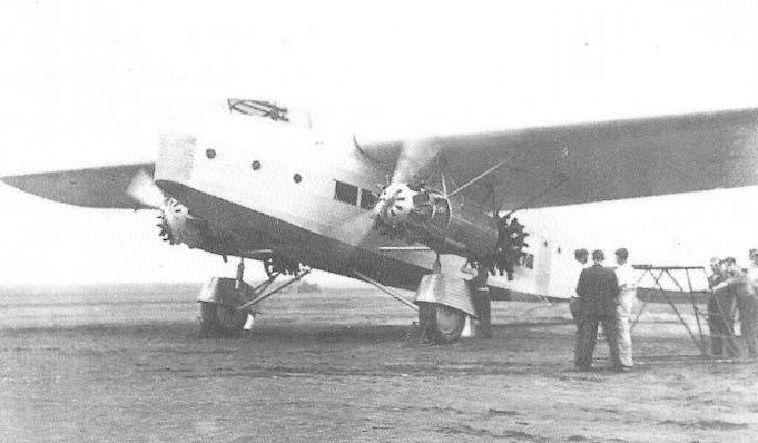
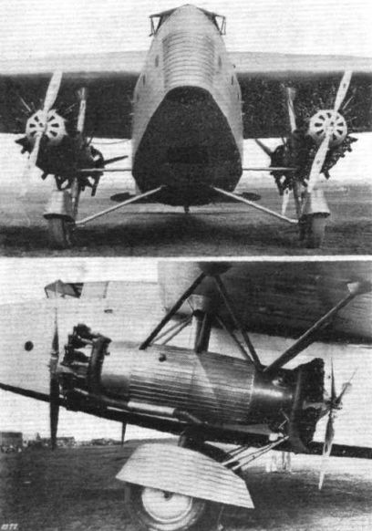
The 4 Pratt & Whitney "Hornet B" engines of 575 h.p. each are mounted in pairs tandem-wise under the wing to the right and left of the fuselage. Each pair of engines is installed in a bed of welded steel tubes, secured to the front and rear wing spars.
The front engines rotate anti-clockwise and the rear engines clockwise. The front airscrews are of the Standard Steel two-bladed tractor type, while three-bladed pusher propellers are used on the rear engines.
Each of the engines has an electric inertia starter. Instead of the customary booster magnetos, vibrating coils are used. A two-way primer cock and pump is installed for each pair of engines. Engine-driven generators are mounted on the two foremost engines.
Each engine exhaust manifold is oval in section to reduce area resistance. The front exhaust manifolds have a single outlet, the rear exhaust manifolds two, one on each side and deflected outward to obtain better diffusion of the exhaust gas in the slip stream. The engine beds are cowled at the sides with fixed panels of corrugated dural, while the engine cowls front and rear are plain sheets merely secured with safety-pins to facilitate engine inspection and servicing.
The heating installation of the cabin is connected up with the front exhaust manifold. The warm air is conducted through two streamline pipes running horizontally between the engine beds and the fuselage to the cabin.
Four fuel tanks are installed between the wing spars; two on either side of the fuselage. Each tank has a capacity of 175 U.S. gallons (662.4 litres), so that the total fuel supply amounts to 700 U.S. gallons (approximately 2,650 litres). The tanks are made of welded sheet aluminium. The fuel system connections are so arranged that the two tanks on either side can feed either front or rear engine, or both, from either one or two tanks. All fuel conduits are outside the fuselage.
A double oil tank is located between the engines in each bed. The tanks are made of welded sheet aluminium, and each tank section has a capacity of 15 U.S. gallons (approximately 57 litres). At the bottom of each tank are nine 1-in. diameter tubes, connecting up with a wide pipe which projects inside the engine bed. The wide pipe takes the air from the front propeller slipstream, blows it through the tubes and exhausts it within the engine-bed cowling. This arrangement provides adequate cooling for the oil supply.
The principal characteristics of the Fokker F.32 are: - Span, 99 ft.; length, 69 ft.; height, 16 ft. 6 in.; wing area, 1,330 sq. ft.; weight, empty, 14,910 lb.; useful load, 9,340 lb.; total weight, 24,250 lb.; wing loading, 18.23 lb./sq. ft.; power loading, 10.6 lb./h.p.; speed range, 63-146.6 m.p.h.; cruising speed, 123 m.p.h.; climb at sea level, 850 ft./min.; service ceiling, 13,000 ft.; range at cruising speed, 770 miles.
Показать полностьюShow all