

Описание
Страна : Великобритания
Год : 1929
Самолет для аэрофотосъемки с экипажем два/три человека
Gloster AS.31 Survey
Фирма "Aircraft Operating Company" занимавшаяся работами по заказам Британского картографического управления, самостоятельно разработала техническое задание на самолет для аэрофотосъемки. Проект был разработан "de Havilland" под обозначением DH.67, но из-за загруженности фирмы другими работами его доработку и производство поручили "Gloster". Двухстоечный биплан цельнометаллической конструкции с полотняной обшивкой имел шасси с хвостовой опорой и был оснащен двумя двигателями Bristol Jupiter XI, установленными на нижнем крыле. Экипаж состоял из пилота и фотографа, который мог вести съемку с рабочих мест в носовой или хвостовой частях фюзеляжа. Внутри последнего оказалось достаточно места для размещения даже фотолаборатории, и Фолланд, отвечавший на "Gloster" за эту машину, предложил альтернативные варианты, предусматривающие размещение пассажиров, раненых или груза, в надежде на коммерческое использование самолета. Получивший обозначение Gloster AS.31 Survey, первый самолет (G-AADO) поднялся в воздух в июне 1929 года. В начале 1930 года его перегнали в Кейптаун для проведения картографирования. После завершения этой работы самолет был куплен ВВС Южной Африки и использовался для аэрофотосъемки до 1942 года. Второй и последний экземпляр машины (K2602) был построен "Gloster" для Министерства авиации и в конце 1931 года передан испытательному центру в Фарнборо, где прослужил почти пять лет.
ТАКТИКО-ТЕХНИЧЕСКИЕ ХАРАКТЕРИСТИКИ
Gloster AS.31 Survey
Тип: самолет для аэрофотосъемки с экипажем два/три человека
Силовая установка: два 9-цилиндровых радиальных двигателя Bristol Jupiter XI мощностью по 525 л. с. (391 кВт)
Летные характеристики: максимальная скорость на высоте 305 м - 211 км/ч; крейсерская скорость 177 км/ч; потолок 6400 м
Масса: пустого 2546 кг; максимальная взлетная 3887 кг
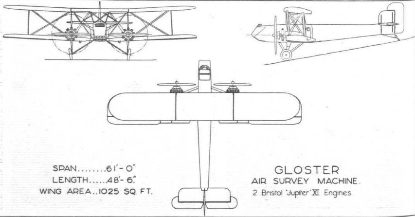
Размеры: размах крыла 18,59 м; длина 14,78 м; высота 5,72 м; площадь крыла 95,22 м2
Описание:
- Gloster AS.31 Survey
- Flight, June 1929
BRITISH AIRCRAFT AT OLYMPIA - Flight, November 1929
”GLOSTER" SURVEY MACHINE
Фотографии

-

Flight 1929-11 / Flight
Регистрационный номер: G-AADO [23] Воздушная фотосъемка стала новым инструментом картографов в 1920-х годах, и Gloster AS.31 Survey создавался в соответствии с требованиями Британского картографического управления. В фюзеляже была организована фотолаборатория, а основное внимание было уделено устойчивости в воздухе и надежности машины.
-

Aeroplane Monthly 2000-04 / S.McKay - Special delivery /Diary of a long-distance flight/ (2)
Регистрационный номер: G-AADO [23] The Palmer Tyre company seized the opportunity in The Aeroplane of April 30, 1930, to advertise its wares as used on the Gloster Survey.
-

Flight 1929-12 / Flight
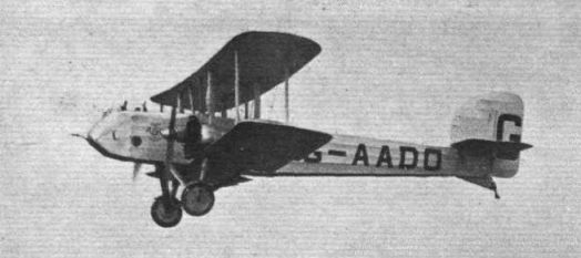
Регистрационный номер: G-AADO [23] The Gloster A.S.31 (2 Jupiter engines), which bids fair to revolutionise air survey work.
-

Aeroplane Monthly 2000-04 / S.McKay - Special delivery /Diary of a long-distance flight/ (2)
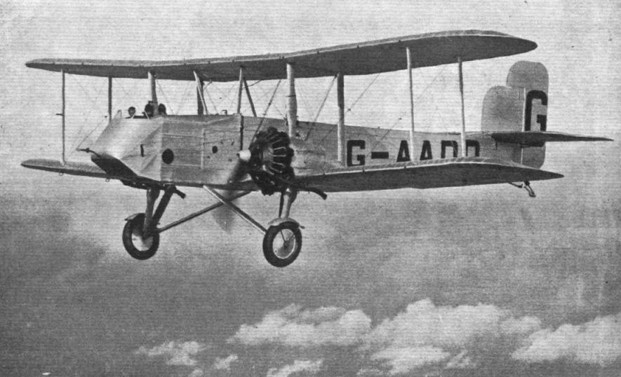
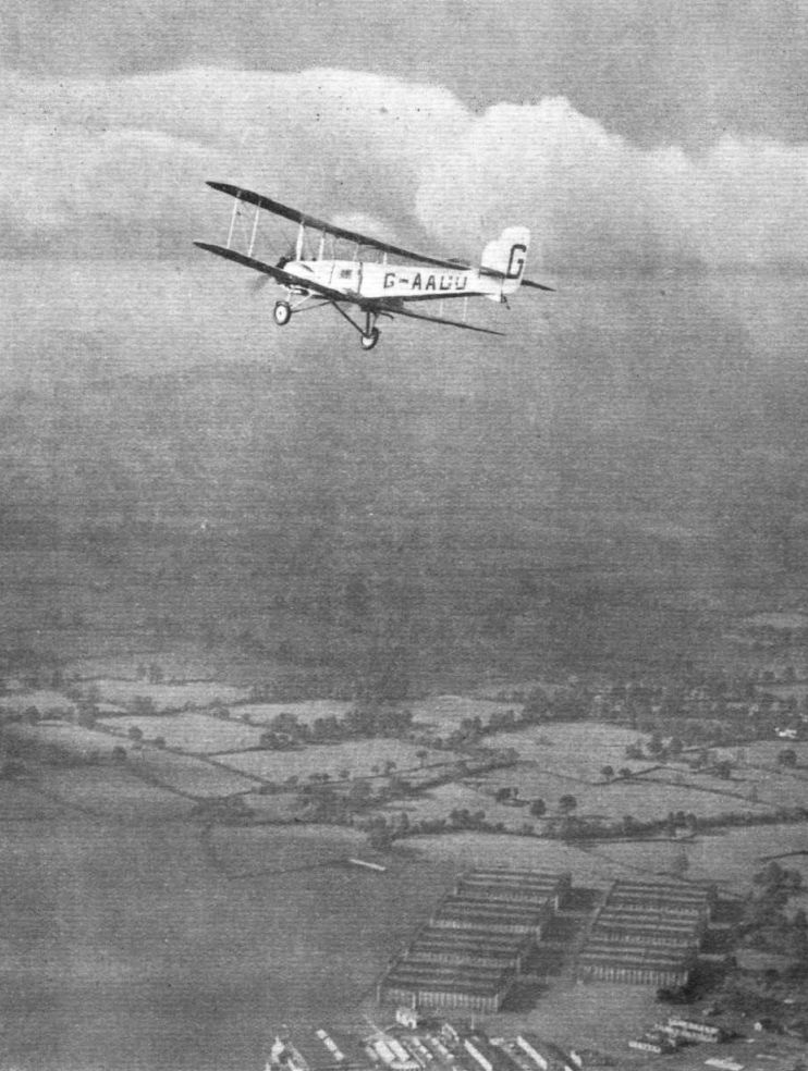
Регистрационный номер: G-AADO [23] A fine air-to-air portrait of Gloster A.S.31 Survey G-AADO. While the biplane’s design offered few concessions to streamlining, it did afford the crew an excellent view from the open cockpit, essential for accurate mapping work.
-

Flight 1930-01 / Flight
Регистрационный номер: G-AADO [23] -

Flight 1929-11 / Flight
Регистрационный номер: G-AADO [23] -

Flight 1930-03 / Flight
Регистрационный номер: G-AADO [23] -

Flight 1929-11 / Flight
Регистрационный номер: G-AADO [23] -

Flight 1930-01 / Flight
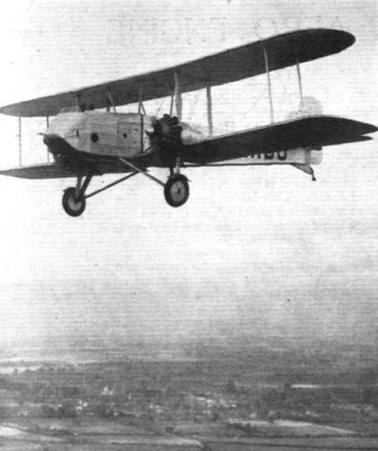
Регистрационный номер: G-AADO [23] The Gloster Survey machine flying with starboard engine throttled right down, and propeller ticking slowly over.
-
Flight 1931-01 / Flight
Регистрационный номер: G-AADO [23] The Gloster AS.31 machine, G-AADO, fitted with two Bristol "Jupiter" engines, about to leave Cape Town for the scene of operations.
-

Flight 1929-11 / Flight Advertisements
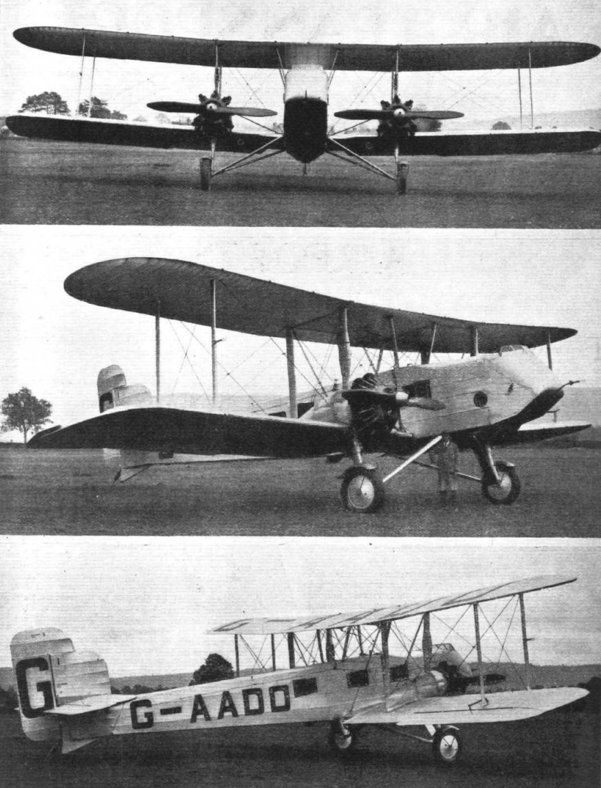
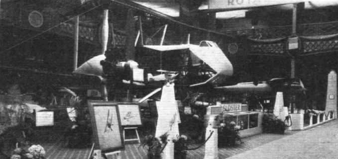
Регистрационный номер: G-AADO [23] Gloster Survey machine, designed and built by the Gloster Aircraft Co. to the order of the Air Survey Co. Ltd. This is the first machine ever designed specially for Air Survey work, and was exhibited in skeleton form at Olympia. The machine has now been completed and doped with Cellon.
-

Aeroplane Monthly 2000-04 / S.McKay - Special delivery /Diary of a long-distance flight/ (2)
Регистрационный номер: G-AADO [23] Kisumu was the first grass aerodrome the flyers had encountered since leaving Europe; although wet, the surface was firm.
-

Aeroplane Monthly 2000-04 / S.McKay - Special delivery /Diary of a long-distance flight/ (2)
Регистрационный номер: G-AADO [23] The Survey is pulled out of the soft ground at Tabora by 100 men of the King’s African Rifles on April 6, 1930.
-

Aeroplane Monthly 2000-04 / S.McKay - Special delivery /Diary of a long-distance flight/ (2)
Регистрационный номер: G-AADO [23] Refuelling the Survey at Beaufort West from a vintage truck. The stop here, in the Karoo Desert, was short.
-
Flight 1929-10 / Flight
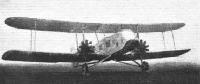
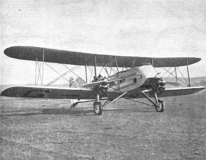
Регистрационный номер: G-AADO [23] THE GLOSTER AIR SURVEY MACHINE: Two of these machines, fitted with Bristol "Jupiter" engines, have been built, of which the one shown is to be put into service by the Aircraft Operating Co. The other is for sale, and would, as an alternative, be very useful as a commercial aeroplane.
-

Flight 1930-01 / Flight
Регистрационный номер: G-AADO [23] Lord Thomson gives his impressions of his flight to the microphone.
-

Aeroplane Monthly 2000-04 / S.McKay - Special delivery /Diary of a long-distance flight/ (2)
Регистрационный номер: G-AADO [23] The parting of the ways as the Butlers leave G-AADO to its owners, the AOC.
-

Aeroplane Monthly 2000-04 / S.McKay - Special delivery /Diary of a long-distance flight/ (2)
Регистрационный номер: G-AADO [23] Inspecting the hole made by one of the aircraft’s wheels at Tabora when landing on April 5, 1930 - underneath the crust was “a soft jelly of very watery mud”.
-

Flight 1931-01 / Flight
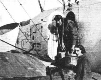
Регистрационный номер: G-AADO [23] Mr. and Mrs. A. S. Butler deplaning from their Gloster "Survey" machine at Wynbird Aerodrome, Cape Town, on their arrival there last April. The Gloster AS.31 machine, G-AADO, fitted with two Bristol "Jupiter" engines, it will be remembered, was flown out from England by Mr. and Mrs. Butler for the important survey work which the Aircraft Operating Co. had undertaken to carry out in Rhodesia.
-

Flight 1930-03 / Flight
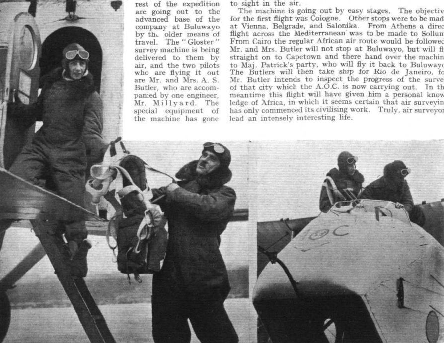
Регистрационный номер: G-AADO [23] OFF TO RHODESIA: Mr. A. S. Butler and Mrs. Butler left Heston Air Park on Thursday last in a "Gloster" Survey Machine with Bristol "Jupiter" engines. On the left Mr. Butler is seen handing a Russell Lobe parachute to his wife. On the right, the two travellers are settling themselves in the cockpit just before the start
-

Aeroplane Monthly 2000-04 / S.McKay - Special delivery /Diary of a long-distance flight/ (2)
Регистрационный номер: G-AADO [23] The arrival at Livingstone - note the AOC emblem on the nose.
-

Aeroplane Monthly 2000-04 / S.McKay - Special delivery /Diary of a long-distance flight/ (2)
Регистрационный номер: G-AADO [23] A page from Lois’s diary with an aerial view of Broken Hill (an X marks the aerodrome), which was the base of the survey to be carried out by the Aircraft Operating Company, and a shot of the Butlers posing with their luggage on arrival.
-

Aeroplane Monthly 2000-04 / S.McKay - Special delivery /Diary of a long-distance flight/ (2)
Регистрационный номер: G-AADO [23] Above: Table Mountain, Cape Town, from G-AADO. Below: Table Bay, and unloading the luggage on arrival.
-

Aeroplane Monthly 2000-04 / S.McKay - Special delivery /Diary of a long-distance flight/ (2)
Регистрационный номер: K2602 The second of only two Gloster Surveys built was K2602, delivered to RAE Farnborough in November 1931 for wireless experiments. It ceased flying in 1936 and was struck off charge in March 1937.
-

Flight 1929-07 / Flight
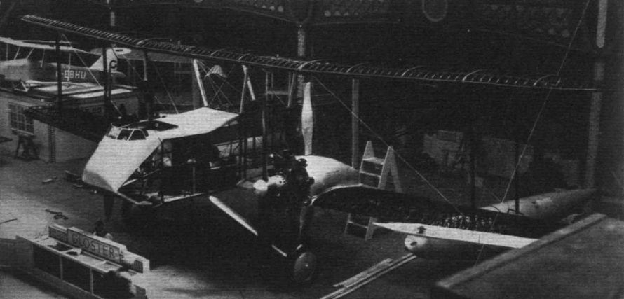
THE GLOSTER AIR SURVEY MACHINE: Contrary to general impression, this machine is for sale, and not built to the order of any particular firm.
-

Flight 1929-07 / Flight
The Gloster Air Survey machine is exhibited in skeleton so that visitors may examine all the details. On the right is seen the "Gloster IV" racing seaplane.
Другие самолёты на фотографии: Gloster IV - Великобритания - 1926
-

Flight 1929-07 / Flight
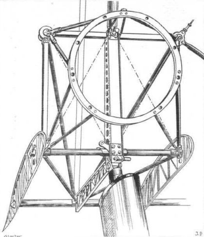
Engine mounting and undercarriage strut attachment on the Gloster Air Survey machine.
-

Flight 1929-07 / Flight
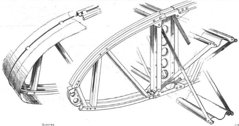
THE GLOSTER AIR SURVEY MACHINE: Details of rib and lattice spar (steel) construction. Note the method of holding the wing fabric on with a wire.
-

Flight 1929-07 / Flight
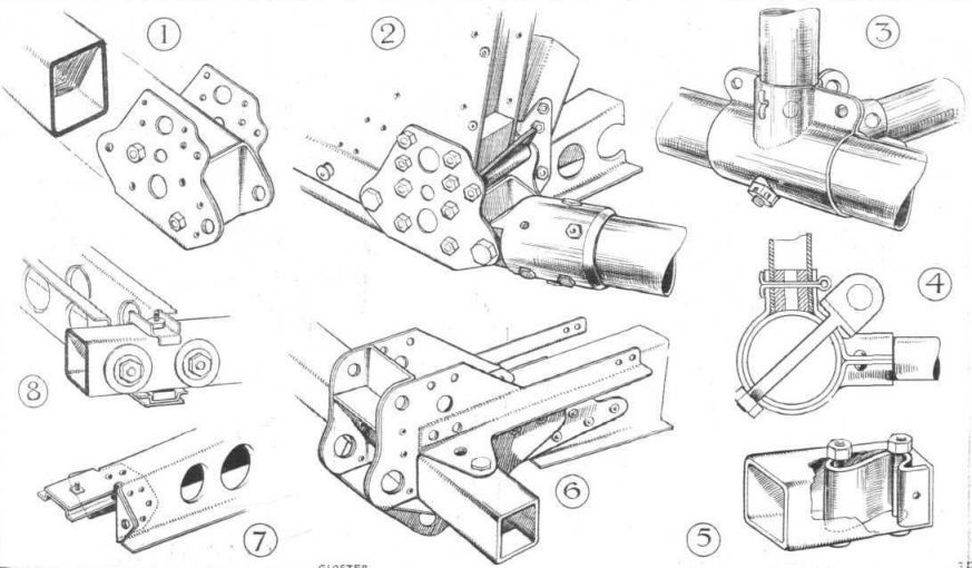
FUSELAGE DETAILS OF GLOSTER AIR SURVEY MACHINE: 1, Square longerons are used in front portion, with flat-plate joints. The rear portion uses round tubes, attached to the square tubes as shown in 2, while 3 shows a typical fuselage (rear portion) joint. This is shown in section in 4. S-shaped strips are used for internal stiffeners, as in 5. Wing and chassis attachments are shown in 6, and flooring in 7 and 8.
-

Flight 1929-07 / Flight
Gloster Air Survey Machine 2 Bristol "Jupiter" XI Engines


- Фотографии