
Фотографии
-
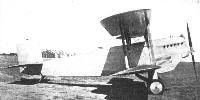
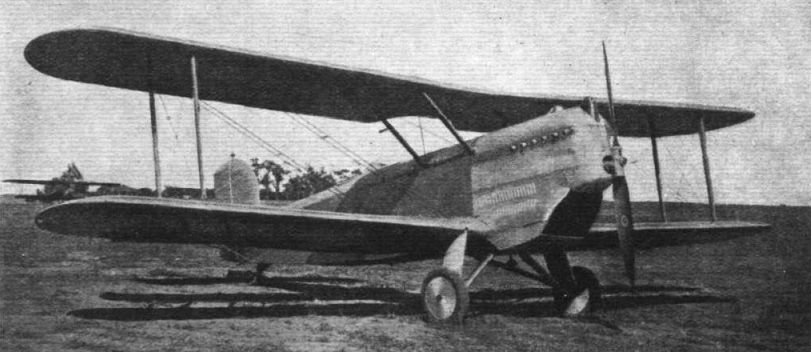
THE DOUGLAS "D.A.M.-2" MAIL PLANE. Side view. A 400 h.p. "Liberty-12" engine is installed.
Самолёты на фотографии: Douglas M-1 - M-4 - США - 1925
-
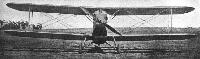
A front view of the Douglas "D.A.M.-2" mail 'plane, showing the thickened wing-roots on the lower plane where the petrol tanks are located.
Самолёты на фотографии: Douglas M-1 - M-4 - США - 1925
-

THE DOUGLAS "D.A.M.-2" MAIL 'PLANE: A three-quarter front view of one of the recent machines produced in America for air mail service.
Самолёты на фотографии: Douglas M-1 - M-4 - США - 1925
-
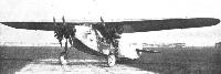
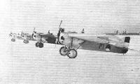
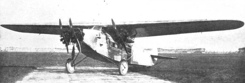
THE FOKKER F.VII-3m: A three-quarter front view. The engines shown in the photograph are Wright "Whirlwinds" of 200 h.p. each, but other engines such as the Armstrong-Siddeley "Lynx," can be substituted.
Самолёты на фотографии: Fokker F.VII / C-2 / F.XIV - Нидерланды - 1924
-

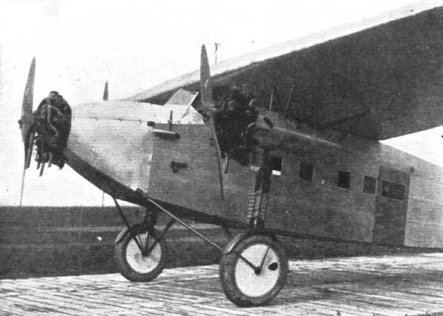
The Fokker F.VII-3m: This photograph shows the mounting of the nose and wing engines, the pilot's cockpit and the undercarriage.
Самолёты на фотографии: Fokker F.VII / C-2 / F.XIV - Нидерланды - 1924
-
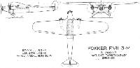
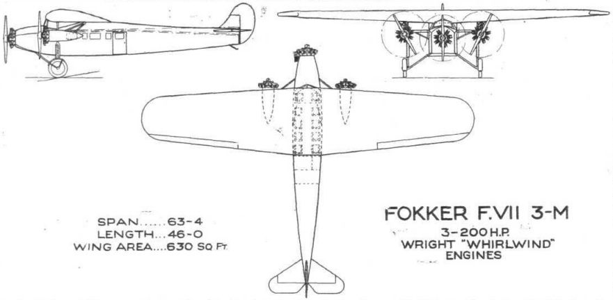
Fokker F.VII 3-M 3-200 h.p. Wright "Whirlwind" Engines
Самолёты на фотографии: Fokker F.VII / C-2 / F.XIV - Нидерланды - 1924
-
ANCIENT AND MODERN: This photograph shows a Dornier "Wal" with two Napier Lion engines and is to be used by Commandant Franco for a flight across the Atlantic via Seville, Cape Verde, Pernambuco, and Buenos Aires, and, possibly, if all goes well, the tour will be continued around the world. The Commandant will be accompanied by Artillery Captain Ruiz Alda, as navigator, and by a mechanic, and hopes to commence his trip early in the New Year. The Dornier "Wal" has an empty weight of 3,500 kgs. (7,700 lbs.) and a useful load of the same amount. Its range is stated to be 3,000 kms. (1,865 miles), and the top speed is given as 205 kms. (127 m.p.h.).
Самолёты на фотографии: Dornier Do.J Wal - Германия - 1922
-

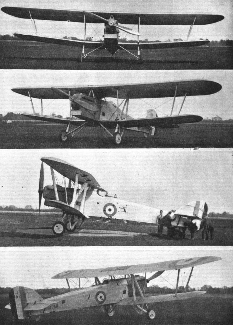
Регистрационный номер: J7511 A HAWKER DAY BOMBER: This photograph shows the Hawker "Horsley," with Rolls-Royce "Condor" engine, which is now going into production for the Royal Air Force. Several unusual features are disclosed by the photographs, but technical details of the machine may not yet be published.
Самолёты на фотографии: Hawker Horsley / Dantorp - Великобритания - 1925
-
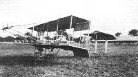
A PRE-WAR "LIGHT 'PLANE": It is interesting to note that this Graham White "box-kite," with its 50 h.p. Gnome engine, would be admitted as a light 'plane under the present definition of the term.
Самолёты на фотографии: Grahame-White biplane / School 'bus - Великобритания - 1912
-

The Avia B.H.11, fitted with a 60-h.p. Walter engine, which was placed first in the Coppa d'Italia, which took place in Rome, November 12-19.
Самолёты на фотографии: Avia BH-9 / BH-10 / BH-11 / BH-12 / BH-16 - Чехословакия - 1923
-

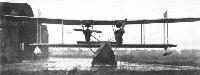
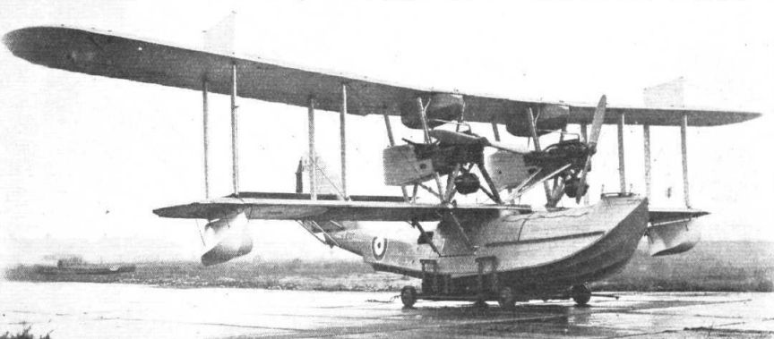
THE "KINGSTON" METAL-HULL FLYING BOAT: This photograph shows the machine in three-quarter front view, and illustrates several unusual features, particularly as regards the form of the planing bottom ahead of the step.
Самолёты на фотографии: Phoenix Cork / P.5 - Великобритания - 1918
-
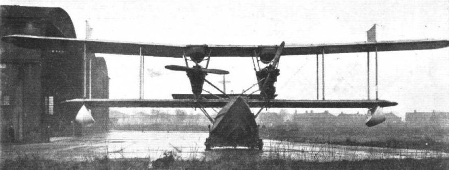
THE "KINGSTON" METAL-HULL FLYING BOAT: The corrugations, or waves, in the transverse sections of the planing bottom, as well as the pronounced "tumble home" to the sides, are well brought out in this front view. The engines are Napier "Lions."
Самолёты на фотографии: Phoenix Cork / P.5 - Великобритания - 1918
-
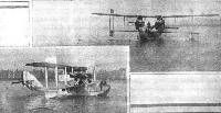
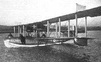
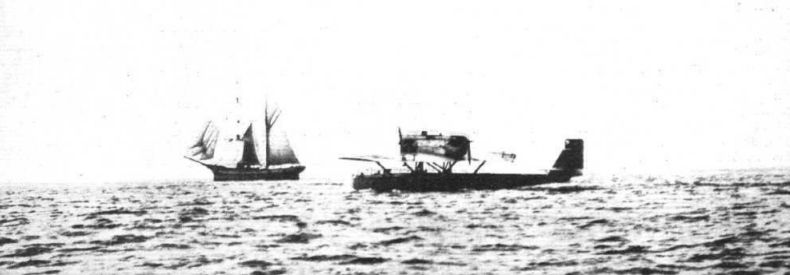
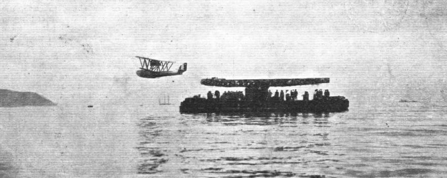
On the sea: Two views of the English Electric Co.'s "Kingston." The boat is notably high in the water, and the small angle of heel while at rest should be noted.
Самолёты на фотографии: Phoenix Cork / P.5 - Великобритания - 1918
-

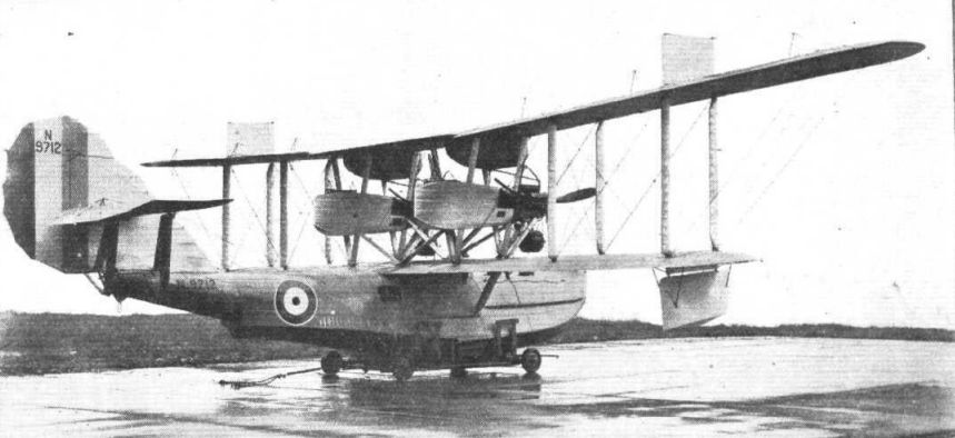
Регистрационный номер: N9712 THE "KINGSTON" METAL-HULL FLYING BOAT: Three-quarter rear view. Note the unusual shape of the engine nacelles.
Самолёты на фотографии: Phoenix Cork / P.5 - Великобритания - 1918
-

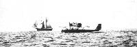
ITALY ADOPTS THE CATAPULT: This photograph, kindly sent to us by General A. Guidoni, Italian Air Attache in London, shows the catapult recently tested at the Navy Yard at Spezia. The catapult, which is similar in design to those used in America, was designed by Major Gagnotto. The weight of the Macchi flying-boat being launched was 3,000 lbs., and its speed 100 m.p.h.
Самолёты на фотографии: Macchi M.18 - Италия - 1920
-
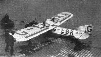
Регистрационный номер: G-EBKA First British flying-boat with all-metal hull: The Short "Cockle" single-seater monoplane, with two Blackburne engines, photographed on the Medway at Rochester on September 18, 1924.
Самолёты на фотографии: Short Stellite / Cockle / S.1 - Великобритания - 1924
-
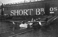
The Short "Cockle" being launched from the slipway at Rochester on March 20, 1925.
Самолёты на фотографии: Short Stellite / Cockle / S.1 - Великобритания - 1924
-
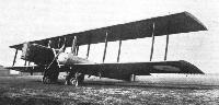
A RECORD BREAKER: The four-engined Farman "Goliath" which has recently established a number of French records and world's records for heavy useful loads. The machine has a span of 35 m. (115 ft.) and a wing area of 266 sq m. (2,806 sq. ft.). The engines (four) are Farman "broad-arrow" types of 500 h.p. each. The weight of the machine empty is 7,150 kgs. (15,750 lbs.), and the normal useful load is4,500 kgs. (10,000 lbs.), giving normally a total loaded weight of 11,650 kgs. (25,750 lbs.). It is stated that the machine has a top speed of 190 km./h. (118 m.p.h.) at ground level. The ceiling, with a useful load of 4,000 kgs., is 5,000 m. (16,400 ft.), and with a useful load of 6,000 kgs. it is 3,500 m. With one engine stopped the ceiling is stated to be 3,800 m. (12,500 ft.).
Самолёты на фотографии: Farman F.140 / F.4S Super Goliath - Франция - 1923
-
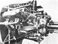
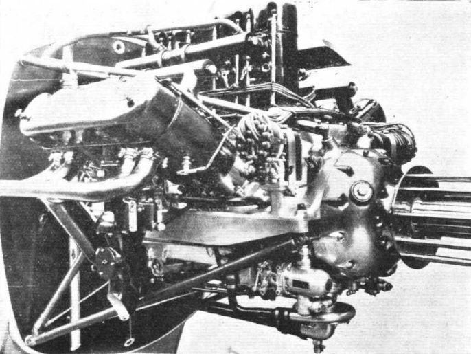
The Farman engine: This photograph shows one of the 500 h.p. Farman engines installed in the four-engined Farman "Goliath," which has established a number of records for weight-carrying.
Самолёты на фотографии: Farman F.140 / F.4S Super Goliath - Франция - 1923
-
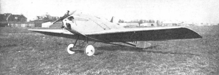
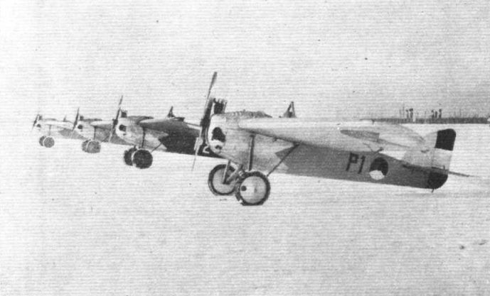
Light 'planes for East India: A batch of Pander light monoplanes built for Dutch East Indies. Note the tubular cabane added over the cockpit to protect the pilot's head in a crash.
Самолёты на фотографии: Holland (VIH) H.2 - Нидерланды - 1924
-
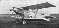
NEW BRITISH AEROPLANE FOR LATVIA: Tha Beardmore W.B.XXVI is a two-seater fighter with Rolls-Royce "Eagle IX" engine. This three-quarter front view shows the unusual wing bracing and the special undercarriage "leg," which gives a travel of no less than 11 in.
Самолёты на фотографии: Beardmore W.B.XXVI - Великобритания - 1925
-

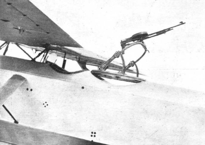
The machine gun and its Scarff ring mounting on the Beardmore W.B.XXVI.
Самолёты на фотографии: Beardmore W.B.XXVI - Великобритания - 1925
-
A NEW WESTLAND MACHINE: The "Yeovil" is a Day-Bomber fitted with Rolls-Royce "Condor" engine. In this front view the Leitner-Watts metal propeller is a notable feature, as are also the high-lift section gravity petrol tanks.
Самолёты на фотографии: Westland Yeovil - Великобритания - 1925
-

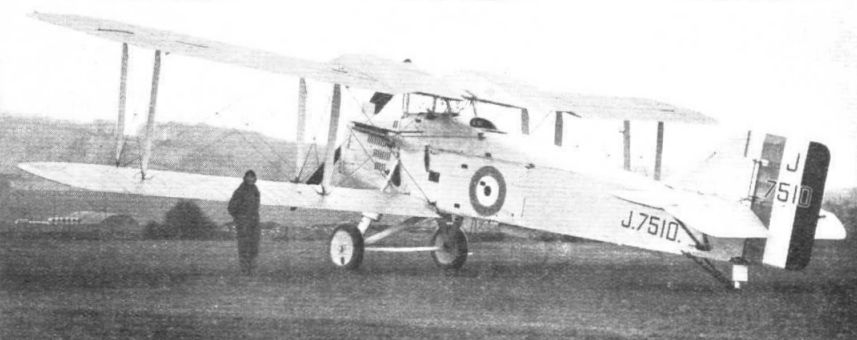
Регистрационный номер: J7510 THE WESTLAND "YEOVIL" DAY-BOMBER: Three-quarter rear view. The sloping deck provides a good view forward for the pilot, while the rear gunner, being clear of the wings, has a very free field of fire and a good view downwards for bomb sighting.
Самолёты на фотографии: Westland Yeovil - Великобритания - 1925
-
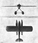
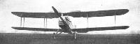
A SCHNEIDER CUP CHALLENGER WHICH DID NOT MATERIALISE: These two photographs of a wind tunnel model have been sent to us by the Dornier Co. of Friedrichshafen, with the information that the Italian "Commissariato d'Aeronautica" stated that wind-tunnel tests On the model in 1924 indicated that the aerodynamic qualities of the machine were such as to give it an excellent chance in the Schneider Cup race. The actual machine was not constructed, however, as the subsidy granted by the Italian Government was insufficient to meet the expense entailed. In the model the wing bracing appears somewhat sketchy and the float shape, although probably of low air resistance, would appear open to criticism.
Самолёты на фотографии: Dornier Schneider Trophy 1924 - Германия - 1925
-
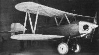
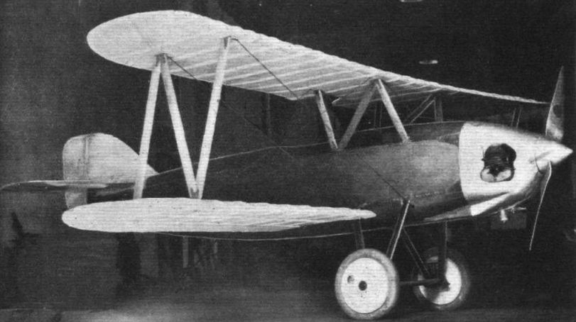
THE POWELL LIGHT 'PLANE: Three-quarter front view. Note the neat cowling around the Bristol "Cherub" engine. The fuselage is covered with ply-wood.
Самолёты на фотографии: Powell PH - США - 1925
-
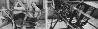
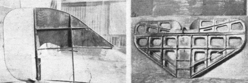
THE POWELL LIGHT 'PLANE: On the left the front portion of the fuselage. The man in the cockpit gives a good idea of the small size of the machine. On the right another view of the pilot's cockpit, showing controls, undercarriage struts, bulkheads, etc.
Самолёты на фотографии: Powell PH - США - 1925
-
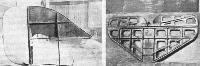
THE POWELL LIGHT 'PLANE: Three-ply wood enters largely into the construction of the tail.
Самолёты на фотографии: Powell PH - США - 1925
-

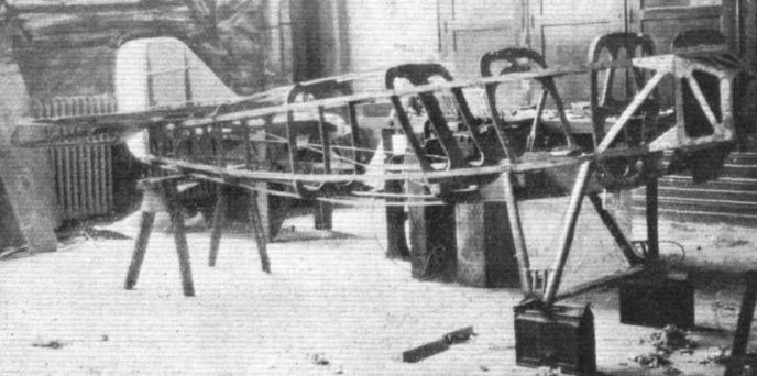
The Powell Light 'Plane: View of the skeleton framework of the fuselage. The undercarriage V's are made of streamline steel tubes.
Самолёты на фотографии: Powell PH - США - 1925
-
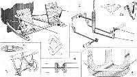
THE POWELL LIGHT 'PLANE: Some constructional features. 1. The rudder pedals which take the place of the more usual foot bar. 1a shows the sheet metal footguards to which the rudder control wires are attached. 2 is a diagrammatic perspective sketch of the elevator and aileron controls, while 2a shows, in the flat and after bending, one of the bell cranks of the aileron control. In 3 and 3a are shown the undercarriage with divided axle. The cross-member is in the form of a channel or trough-section metal strut in which the axles are housed, and which is streamlined with wood fairings. 4 shows the leather hinge used in elevator and rudder, while 5 is a bulkhead with lift wire attachments.
Самолёты на фотографии: Powell PH - США - 1925
-

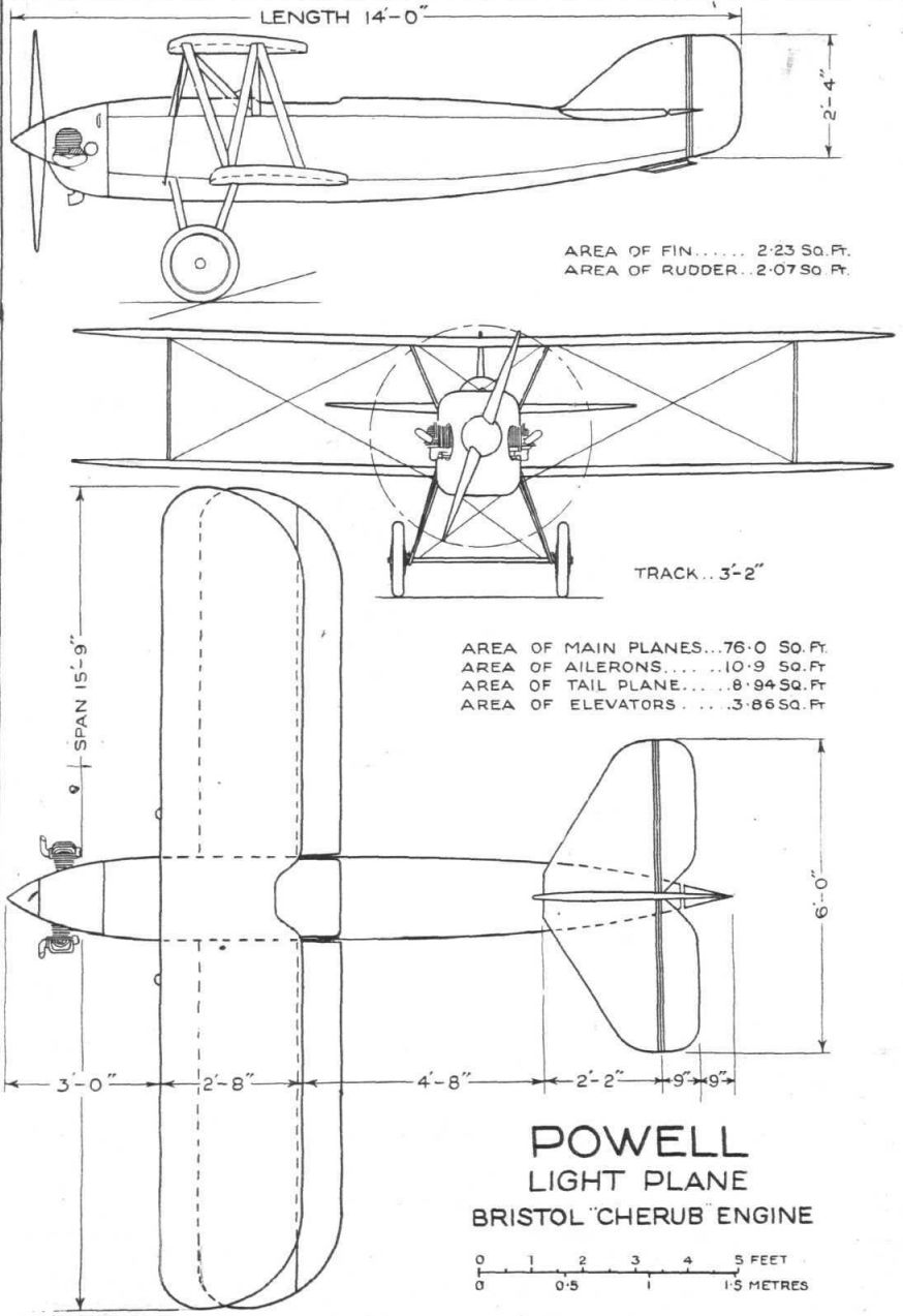
Powell Light Plane Bristol "Cherub" Engine
Самолёты на фотографии: Powell PH - США - 1925
-
Регистрационный номер: N177 The Short F.5 with all-metal hull: Photographed on the water after a flight on January 5, 1925.
Самолёты на фотографии: Short S.2 - Великобритания - 1925


Статьи
- Flight