
Фотографии

-

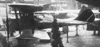
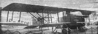
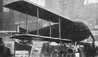
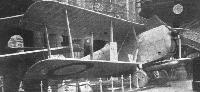
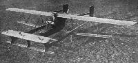
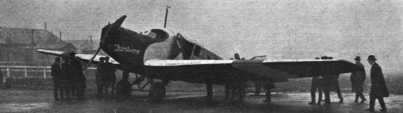
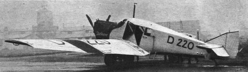
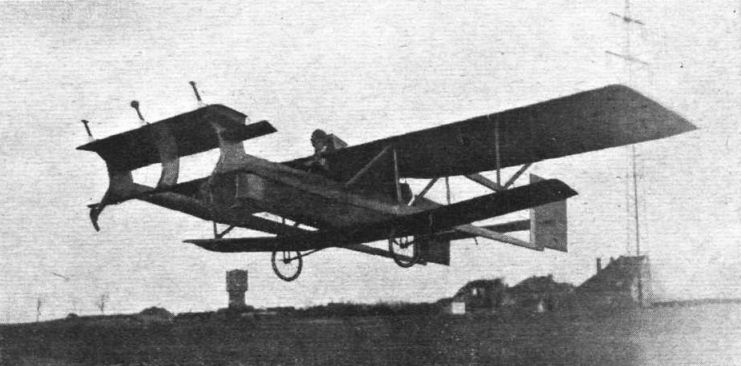
Регистрационный номер: D-220 [5] THE JUNKERS MONOPLANE: Three-quarter front view.
Самолёты на фотографии: Junkers F 13 - Германия - 1919
-

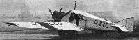
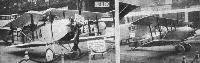
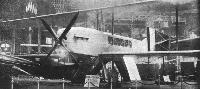
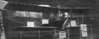
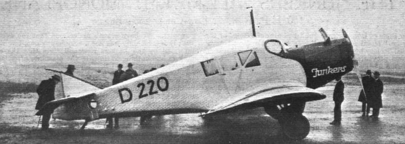
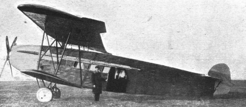
Регистрационный номер: D-220 [5] THE JUNKERS MONOPLANE: Side view.
Самолёты на фотографии: Junkers F 13 - Германия - 1919
-
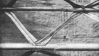
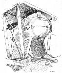
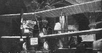
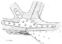
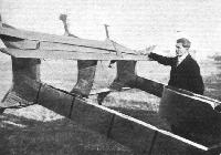
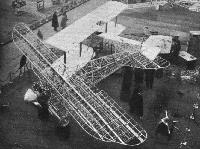
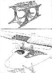
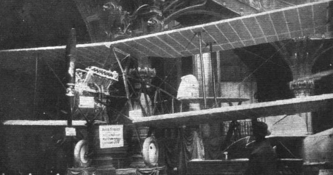
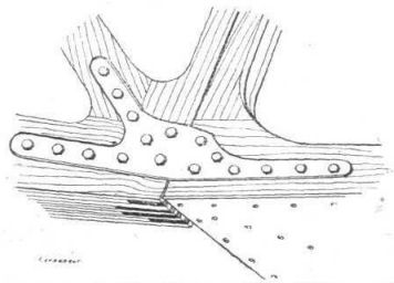
The Junkers Monoplane: This photograph, a slide of which was shown at Professor Junkers' lecture, illustrates the wing construction. Note how bracing strips are merely riveted to sides of tube.
Самолёты на фотографии: Junkers F 13 - Германия - 1919
-
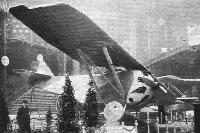
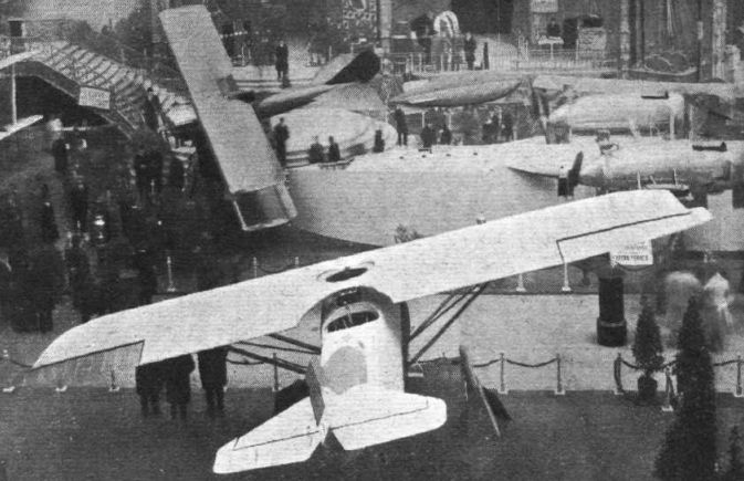
Регистрационный номер: D-220 [5] THE JUNKERS MONOPLANE: Three-quarter rear view.
Самолёты на фотографии: Junkers F 13 - Германия - 1919
-
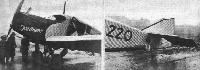
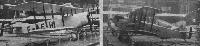
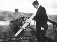
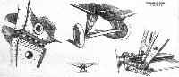
Регистрационный номер: D-220 [5] THE JUNKERS MONOPLANE: On the left, view of the engine housing and undercarriage. On the right a view of the tail.
Самолёты на фотографии: Junkers F 13 - Германия - 1919
-
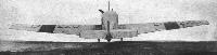
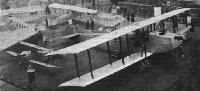
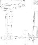
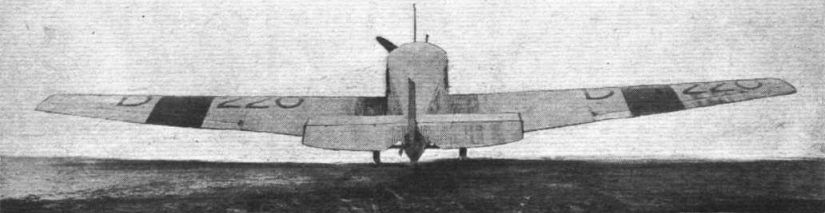
Регистрационный номер: D-220 [5] THE JUNKERS MONOPLANE: Rear view. This illustration gives a good idea of the large span of the machine.
Самолёты на фотографии: Junkers F 13 - Германия - 1919
-
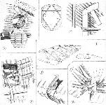
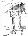
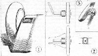
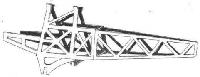
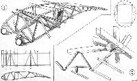
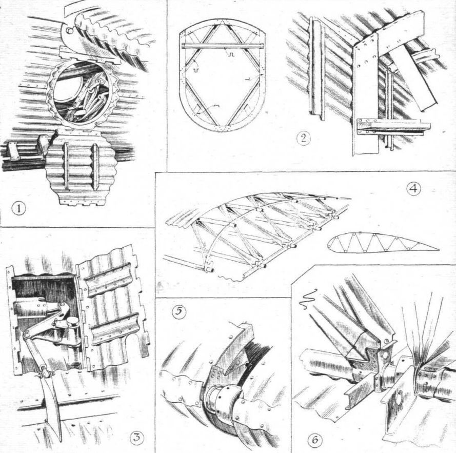
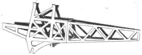
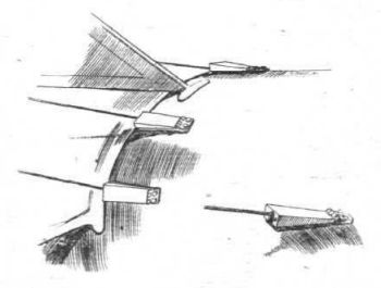
THE Junkers Monoplane: Some sketches of constructional details. 1 shows the inspection door in the side of the fuselage which gives access to the tail skid. The large tube runs to the elevator crank. The trimming tank is just in front of the door, inside the body. 2, details of the fuselage construction. No longerons are used, the corrugations of the covering taking the place of separate longitudinal members. 3 shows the aileron tube-and-crank control which takes the place of cables. 4 is a general view of the wing construction. The small inset is a diagram of the wing section, showing approximate location of spars and bracing strips. 5, the union joint in the front spar. 6, a typical joint between wing root spars and the spars of the end pieces. In the wing roots the bracing members are tubular, whereas in the end pieces the spars only are tubular, the bracing members being made from strip metal, crinkled as indicated in the two sections.
Самолёты на фотографии: Junkers F 13 - Германия - 1919
-
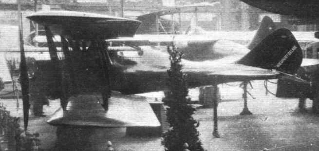
Nieuport-Delage: The 29 C-1, 1923, has two pairs of interplane struts on each side, and a Gottingen wing section.
Самолёты на фотографии: Nieuport Nieuport-29 - Франция - 1918
-
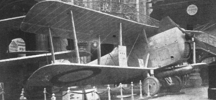
NIEUPORT-DELAGE: This single-strutter biplane chaser is designed for fighting at low altitudes, whereas the two-strutter is intended for fighting at high altitudes.
Самолёты на фотографии: Nieuport Nieuport-29 - Франция - 1918
-
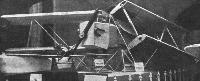
The Pescara Helicopter, as seen from the gallery.
Самолёты на фотографии: Pescara No.3 - Франция - 1923
-
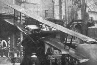
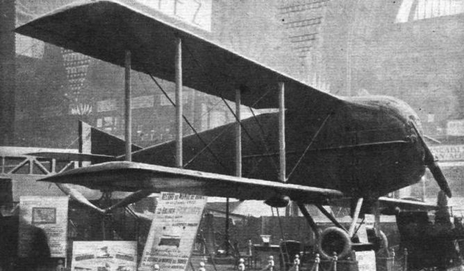
A Caudron Veteran: The type G.3, on which so many of our war pilots received their first tuition.
Самолёты на фотографии: Caudron G.3 - Франция - 1913
-
Регистрационный номер: F-ESAA TWO CAUDRON SPORTING TYPES: On the left the 45 h.p. two-seater, and on the right the 35 h.p. single-seater.
Самолёты на фотографии: Caudron C.27 / C.59 / C.60 - Франция - 1921
-
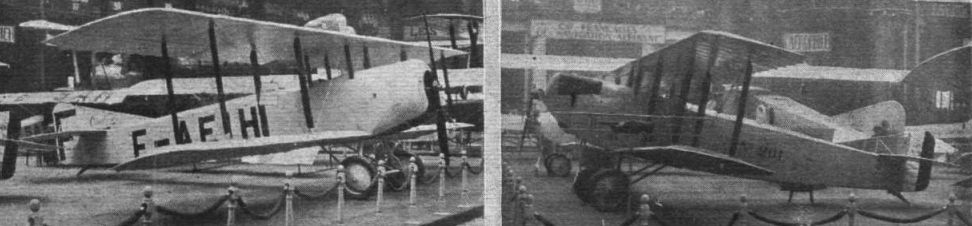
Регистрационный номер: F-AEIH TWO CAUDRON SCHOOL MACHINES: Left, the 80 h.p. le Rhone machine; and right, the Hispano-engined biplane.
Самолёты на фотографии: Caudron C.27 / C.59 / C.60 - Франция - 1921
-
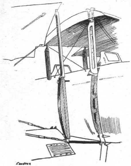
A divided strut is used in the Caudron sporting two-seater in connection with the wing-folding gear. When the wings are open the strut rests in a slot in the side of the fuselage.
Самолёты на фотографии: Caudron C.27 / C.59 / C.60 - Франция - 1921
-

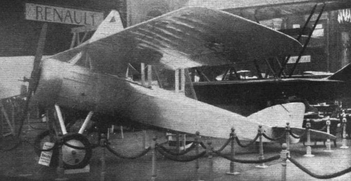
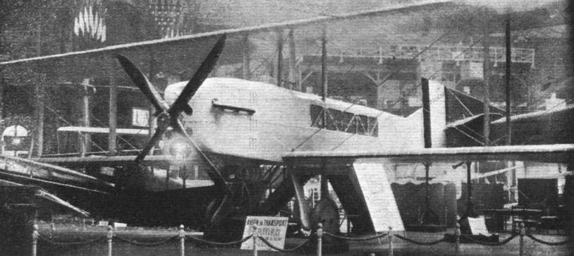
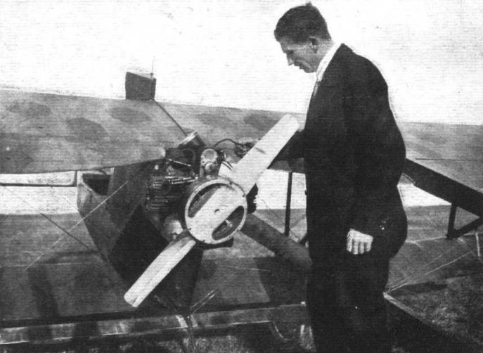
MORANE-SAULNIER: The parasol monoplane was fitted with a Leitner-Watts metal airscrew.
Самолёты на фотографии: Morane-Saulnier AR (MS-35) / AS (MS-36) - Франция - 1915
-
The Farman day bomber is of somewhat unusual appearance. The machine is built almost entirely of metal.
Самолёты на фотографии: Farman B.2 - Франция - 1924
-
The Farman " Commercial " biplane carries eight passengers, and has an engine of 600 h.p.
Самолёты на фотографии: Farman F.130 - Франция - 1922
-

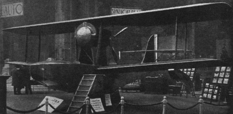
The F.B.A. Flying Boat: Three-quarter front view.
Самолёты на фотографии: FBA Type 16 / 17 - Франция - 1923
-
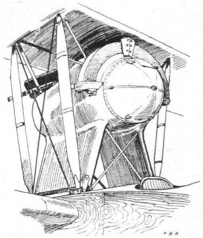
The engine mounting on the F.B.A.
Самолёты на фотографии: FBA Type 16 / 17 - Франция - 1923
-

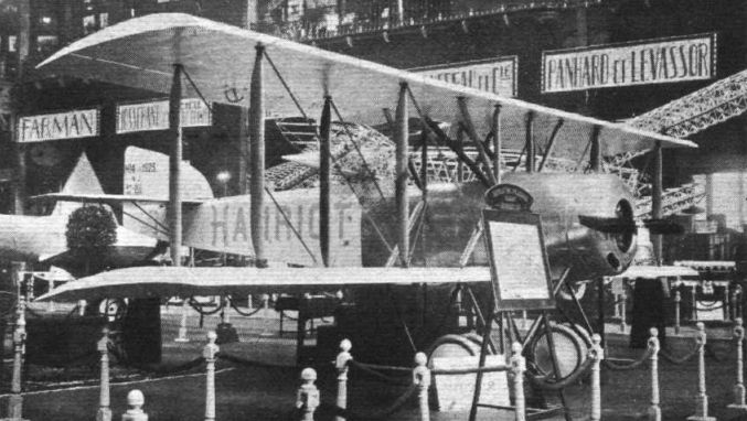
The Hanriot school machine, type H.14.
Самолёты на фотографии: Hanriot HD.14 / HD.17 / HD.32 / HD.41 - Франция - 1920
-

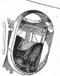
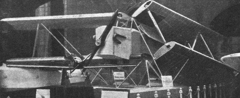
A Study in Angles: In the foreground the Koolhoven F.K.31. Beyond this machine can be seen, also mounted as if on a banked turn, one of the Nieuport biplanes. The large fuselage in the middle is that of the Astra Torres airship, a small scale model of which is also shown. This particular view of the F.K.31 gives an excellent idea of the manner in which the cockpits are arranged.
Самолёты на фотографии: Koolhoven FK-31 - Нидерланды - 1922
-
The Koolhoven F.K.31, with Bristol "Jupiter" engine: Owing to the fact that the machine is a monoplane, and to the arrangement of the cockpits, both pilot and gunner have a particularly unobstructed view in all directions.
Самолёты на фотографии: Koolhoven FK-31 - Нидерланды - 1922
-
THE KOOLHOVEN F.K.31: Some constructional details: 1. External view of shock absorber and axle fairing, 2. Diagrams of shock absorbing gear, which is so arranged that the axle is totally surrounded by the rubber. The outer end of the axle box is split, so that when the load comes on the wheel the rubber presses the sides of this box together, forcing them against the spool on the axle, thus acting as a brake. This action takes place both when the wheel rises under load and when it recoils after a bump, so that the arrangement acts as a damper gear. 3 shows one of the streamline handles which hold the fuselage covering in place. By undoing two of these handles on each side the entire side covering can be removed, exposing the internal Structure for inspection or repair.
Самолёты на фотографии: Koolhoven FK-31 - Нидерланды - 1922
-
The Pierre Levasseur Torpedo 'Plane: Generally speaking, the design of this machine resembles that of the Blackburn "Swift."
Самолёты на фотографии: Levasseur PL.2 - Франция - 1922
-
The Pierre Levasseur Navy Type: This machine has a very unusual fuselage construction, consisting of a few panels of multiply wood, and should be extremely cheap to build.
Самолёты на фотографии: Levasseur PL.3 / PL.4 - Франция - 1924
-
THE PIERRE LEVASSEUR NAVY TYPE: Diagrammatic sketch showing panel construction of the fuselage.
Самолёты на фотографии: Levasseur PL.3 / PL.4 - Франция - 1924
-
THE PIERRE LEVASSEUR NAVY TYPE: Detail sketch showing method of multi-ply construction of the panels.
Самолёты на фотографии: Levasseur PL.3 / PL.4 - Франция - 1924
-
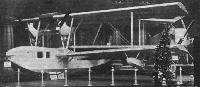
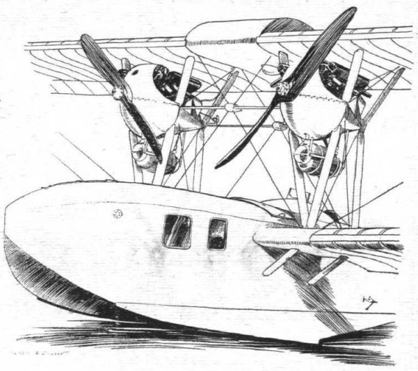
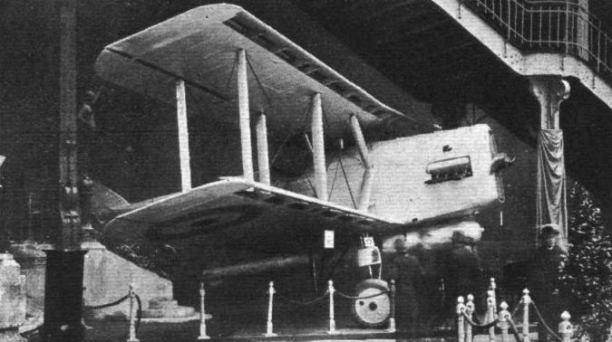
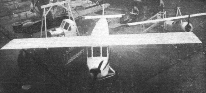
The Liore and Olivier Flying Boat: The two Hispano engines are mounted close together above the cabin. The pilot sits behind the wings.
Самолёты на фотографии: Liore et Olivier LeO H.13 - Франция - 1922
-
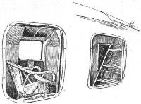
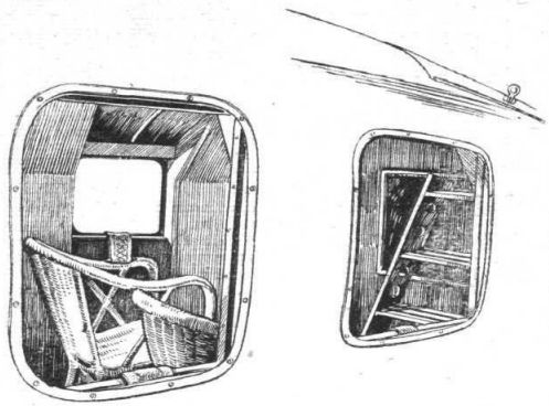
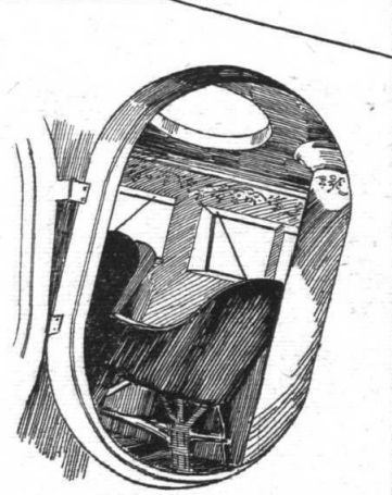
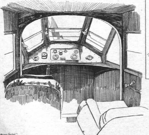
Looking through the windows into cabin of LeO H.13.
Самолёты на фотографии: Liore et Olivier LeO H.13 - Франция - 1922
-
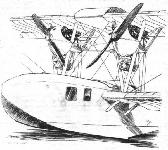
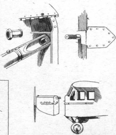
Engine mountings and front of hull of LeO H 13.
Самолёты на фотографии: Liore et Olivier LeO H.13 - Франция - 1922
-
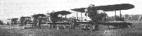
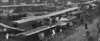
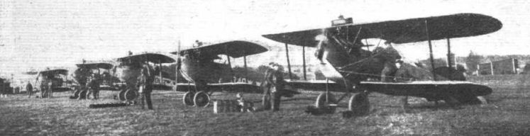
Aviation in Sweden: Some single-seater Fighters lined up for a cross-country handicap contest, between Malmslatt - Stockholm - Orebro - Malmslatt, held last year for Swedish military pilots.
Самолёты на фотографии: Phonix D.I/D.II/D.III - Австро-Венгрия - 1917
-
Henry Potez Sports Model: This machine is fitted with a 70 h.p. Anzani engine, and carries pilot and one passenger.
Самолёты на фотографии: Potez Potez VIII - Франция - 1919
-
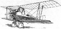
The Henry Potez Type VIII School Machine: The engine is a 70 h.p. Anzani.
Самолёты на фотографии: Potez Potez VIII - Франция - 1919
-
The fibre block cable guides on the Potez VIII are provided with a hinged metal protector.
Самолёты на фотографии: Potez Potez VIII - Франция - 1919
-

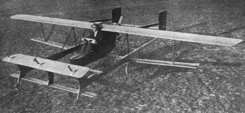
THE BUDIG GLIDER IN FLIGHT, PROPELLED BY ITS 4 H.P. ENGINE: This machine was entered for the Rhon competition of 1921, but did not then do anything very startling.
Самолёты на фотографии: Budig, Friedrich Wilhelm glider - Германия - 1921
-
The front plane of the Budig glider has a "concertina" arrangement which is stated to be designed with a view to giving longitudinal stability. It is difficult, from the illustration, to make out exactly what this arrangement is supposed to do.
Самолёты на фотографии: Budig, Friedrich Wilhelm glider - Германия - 1921
-
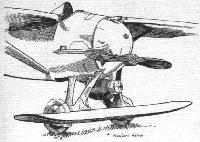
The Budig glider is fitted with a small B.M.W. motor-cycle engine of 4 h.p. The peculiar propeller is, no doubt, a result of the designer having had to mount it on the flywheel of the engine.
Самолёты на фотографии: Budig, Friedrich Wilhelm glider - Германия - 1921
-
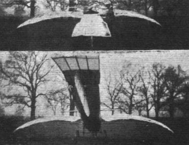
THE BUDIG GLIDER WITH AUXILIARY ENGINE: Three-quarter front view from above. The machine has both front and rear elevators, and in addition the small leading plane is arranged to give automatic stability.
Самолёты на фотографии: Budig, Friedrich Wilhelm glider - Германия - 1921
-
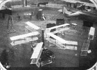
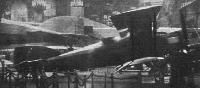
The Caudron three-engined machine, photographed from the gallery.
Самолёты на фотографии: Caudron C.61 / C.81 / C.183 - Франция - 1921
-
A peep into the cabin of the Caudron three-engined machine.
Самолёты на фотографии: Caudron C.61 / C.81 / C.183 - Франция - 1921
-
HENRY POTEZ: The three-engined passenger machine is a development of the three-engined biplane exhibited last year.
Самолёты на фотографии: Potez Potez X / XVIII / XXII - Франция - 1921
-

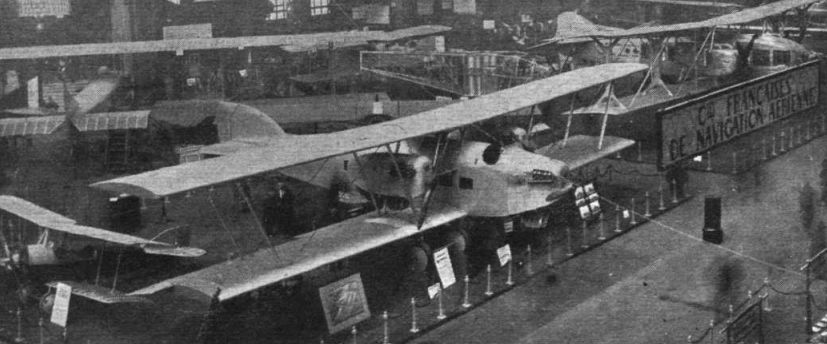
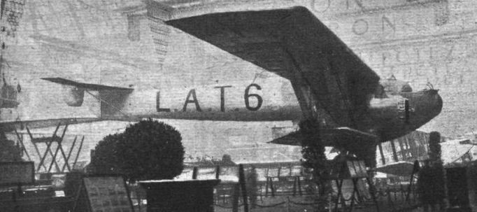
The Giant of the Show: The huge Latecoere four-engined, all-metal biplane.
Самолёты на фотографии: Latecoere Late 6 - Франция - 1924
-

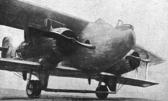
The Latecoere L.A.T.6: Front view of machine, showing nose of fuselage and also the new undercarriage.
Самолёты на фотографии: Latecoere Late 6 - Франция - 1924
-

The Handley Page "Hanley."
Самолёты на фотографии: Handley Page Hanley/H.P.19 / Hendon/H.P.25 - Великобритания - 1922
-

The Morane-Saulnier Cabin Machine: Known as the type A.V., this cantilever monoplane is fitted with a detachable engine unit, in which all engine controls and engine instruments form part of, and are removed with, the unit. In the background may be seen such a unit, mounted on a sectioned portion of a fuselage.
Самолёты на фотографии: Morane-Saulnier AV - Франция - 1922
-
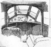
THE MORANE-SAULNIER CABIN MONOPLANE: A view inside the cabin, showing pilot's seat, instrument-board, etc. The square panel in the centre of the instrument-board contains all the engine instruments, and is removed with the engine unit, of which it forms a permanent part.
Самолёты на фотографии: Morane-Saulnier AV - Франция - 1922
-
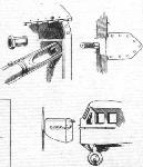
THE MORANE-SAULNIER CABIN MONOPLANE: One of the four bolt attachments which secure the engine unit to the fuselage, while in the bottom corner is shown, diagrammatically, the quick-detachable engine unit, with engine instruments, throttle controls, etc.
Самолёты на фотографии: Morane-Saulnier AV - Франция - 1922
-
The Hanriot all-metal biplane: This view, taken from above, gives a good idea of the single-spar wing construction. Both in the fuselage and wings, channel section Duralumin is used extensively.
Самолёты на фотографии: Hanriot H.26 - Франция - 1923
-
SOME HANRIOT DETAILS: Fig. 1 shows a small portion of the lower plane, which is built up of channel-section ribs and stringers over rectangular section Duralumin tube spars. In the inset is shown the system of triangulation which takes the place of internal drag and torsion bracing. Fig. 2 shows the fuselage construction which is of channel-section Duralumin for longerons and triangulating struts. A number of light stringers are added to the main structure, as shown in the inset.
Самолёты на фотографии: Hanriot H.26 - Франция - 1923
-
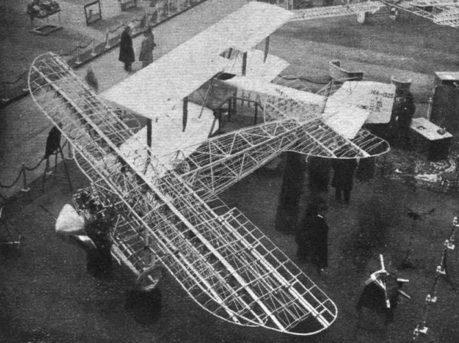
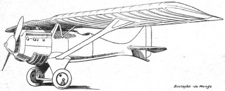
THE DE MONGE-BUSCAYLET MONOPLANE: This machine is built entirely of metal, mostly Duralumin, with the exception of the rear portion of the fuselage, which is a wood monocoque.
Самолёты на фотографии: De Monge Type 5.2 - Франция - 1922
-
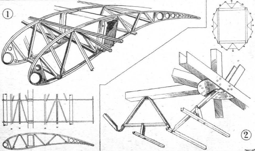
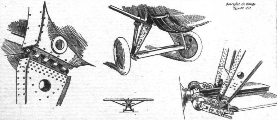
THE DE MONGE-BUSCAYLET, TYPE "52 C-1": The upper sketch shows the undercarriage, while on the left and right are shown upper and lower ends of the undercarriage box struts. Note the friction device which acts as a damper gear. The small inset shows the front elevation of the machine, with thin centre-section. The wings have a very pronounced sweep back.
Самолёты на фотографии: De Monge Type 5.2 - Франция - 1922
-

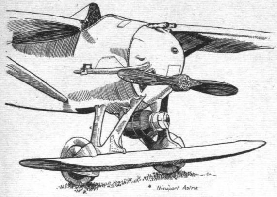
NIEUPORT-DELAGE: The "Sesquiplan" is similar to the racer built for the Coupe Deutsch, and has its wheels mounted in cut-out portions of the small undercarriage plane.
Самолёты на фотографии: Nieuport-Delage Ni-D-37 - Франция - 1923
-
THE NIEUPORT-DELAGE 37 C-1: Note the position of the pilot in front of the wing. The auxiliary plane is fitted chiefly to shift the centre of pressure forward.
Самолёты на фотографии: Nieuport-Delage Ni-D-37 - Франция - 1923
-

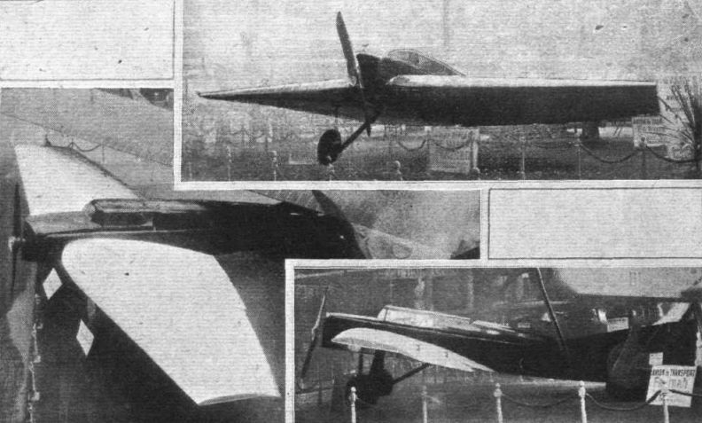
Three views of the Farman monoplane.
Самолёты на фотографии: Farman F.200 - Франция - 1923
-
THE HENRY POTEZ FIGHTER: This is a biplane of orthodox design and construction.
Самолёты на фотографии: Potez Potez XI - Франция - 1922
-
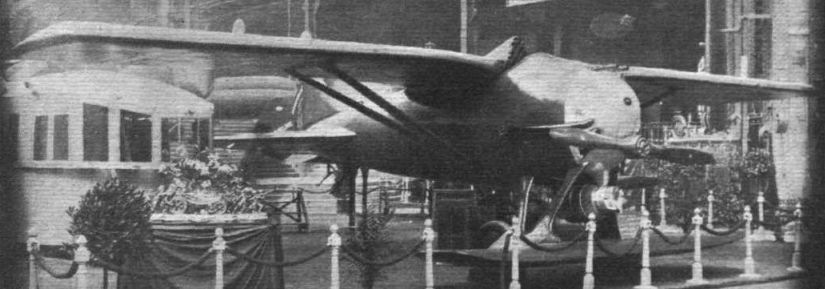
THE LIORE AND OLIVIER TWIN-FLOAT SEAPLANE: Note the peculiar attitude taken up by the folded wings, owing to the angularity of the strut on which the wings are hinged. The wing section is Gottingen 430.
Самолёты на фотографии: Liore et Olivier LeO H.10 - Франция - 1923
-

THE NEW FOKKER F.5: This machine has seating accommodation for eight passengers, and a feature of the design is that the lower plane can be removed in a few minutes, thus turning the machine into a parasol monoplane. The engine is a Rolls-Royce "Eagle."
Самолёты на фотографии: Fokker F.V - Нидерланды - 1922
-
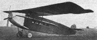
The Fokker F.V. commercial aeroplane (350 h.p. Rolls-Royce): This machine, previously illustrated in FLIGHT as a biplane, is shown here as a monoplane, to which form it may be converted from the biplane in about 15 mins. As a mono, it has a total weight of 3,904 lbs., an area of 484 sq. ft., and a speed of 118 m.p.h.
Самолёты на фотографии: Fokker F.V - Нидерланды - 1922
-

M.PASSAT'S EXPERIMENTAL GLIDER: M.Passat, well-known to many of our readers in connection with his "orthopter" experiments, is testing a new theory - in which movable wings and a variable "c.g." play main parts - with the aid of the glider shown above at Wimbledon. We hope to have something more to say on this subject later on.
Самолёты на фотографии: Passat Sea-gull - Великобритания - 1912
-
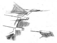
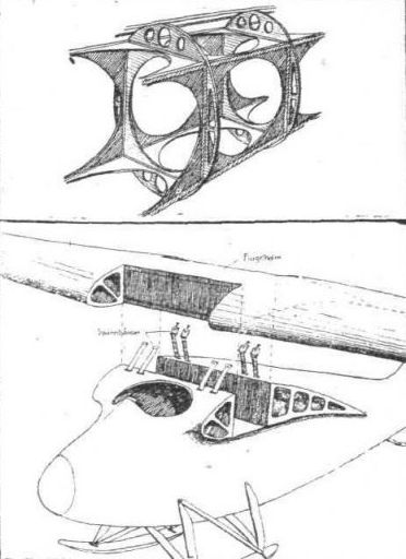
THE STUTTGART MONOPLANE GLIDER: Above, sketch of fuselage construction; below, a perspective sketch showing manner in which wing is located on fuselage.
Самолёты на фотографии: Akaflieg Stuttgart II - Германия - 1922
-
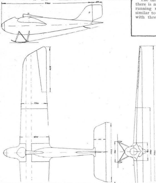
THE STUTTGART MONOPLANE GLIDER: General arrangement drawings.
Самолёты на фотографии: Akaflieg Stuttgart II - Германия - 1922


Статьи
- Flight