
Фотографии

-

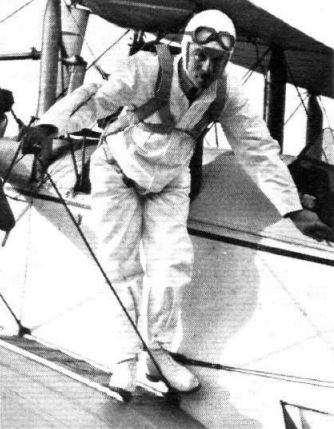
The parachutist still provides a certain attraction, and Mr. Stewart is here seen ready with his Russell-Lobe parachute on the wing of Sir Alan's D.H. 9.
Самолёты на фотографии: De Havilland D.H.9 - Великобритания - 1917
-
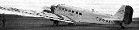
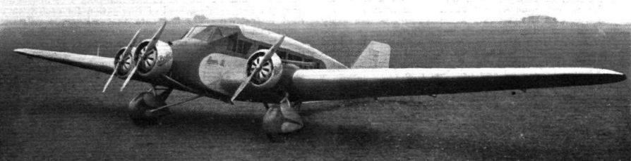
Регистрационный номер: CV-FAI FOR BLAZING THE TRAIL: The Junkers J.52, "Romania," in which Prince George Bibesco, President of the International Aeronautical Federation, is carrying out a survey flight from Paris to Madagascar with a view to finding the shortest and most suitable air route, and to map out new petrol and supply stations.
Самолёты на фотографии: Junkers Ju.52/3m - Германия - 1931
-

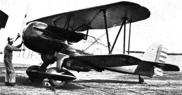
A NEW AMERICAN PERSUIT PLANE: The Curtiss P 6-E biplane which was recently tested for the U.S. Army Air Service at Mitchel Field. It is claimed to have a ground speel of 220 m.p.h. or over 300 m.p.h. in a dive.
Самолёты на фотографии: Curtiss P-6 / Model 35 - США - 1927
-

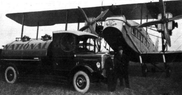
The fuel supply is of paramount importance on a tour like this, and throughout this National Benzole lorry will accompany the outfit to each aerodrome.
Самолёты на фотографии: Handley Page H.P.18 (W.8) / H.P.30 (W.10) - Великобритания - 1919
-

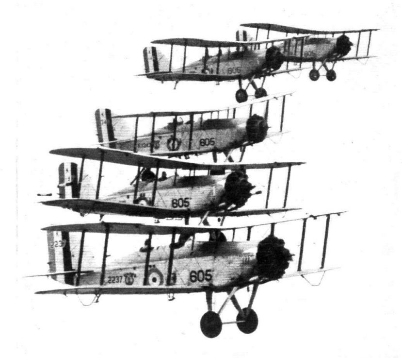
Регистрационный номер: K2237 [2] Самолёты на фотографии: Westland Wapiti - Великобритания - 1927
-

Регистрационный номер: K2237 [2] Самолёты на фотографии: Westland Wapiti - Великобритания - 1927
-

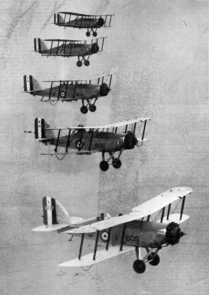
Самолёты на фотографии: Westland Wapiti - Великобритания - 1927
-

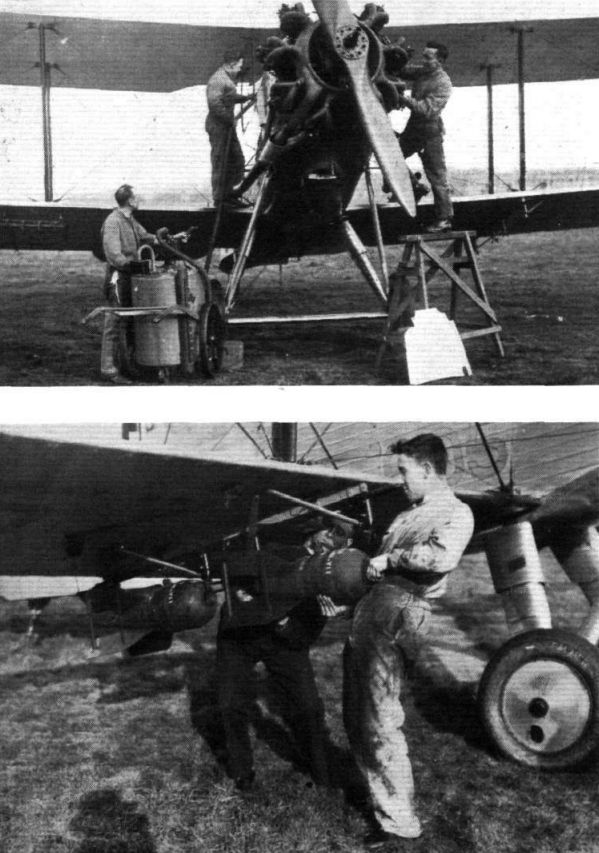
Регистрационный номер: K1147 Westland Wapiti IIA K1147, serving with No 605 (Castle Bromwich) Squadron, Auxiliary Air Force, is started by a petrol-engine driven compressor connected to its gas starter system.
Самолёты на фотографии: Westland Wapiti - Великобритания - 1927
-

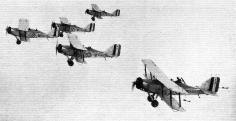
Самолёты на фотографии: Westland Wapiti - Великобритания - 1927
-

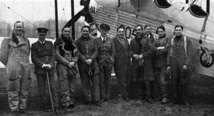
A group of officers of No. 605 B.S.: Names left to right - P/O. W. C. Barnaby; F/O. H. Seidenberg; F/O. J. P. Huins; Flt. Lt. G. V. Perry; Sqd. Ldr. J. A. C. Wright, A.F.C., T.D., Commanding Officer; Flt. Lt. S. D. Macdonald, D.F.C., Adjutant; F/O. M. V. de Satge, Asst. Adjutant; P/O. G. Wright ; F/O. J. M. Abell; F/O. B. P. A. Vallance.
Самолёты на фотографии: Westland Wapiti - Великобритания - 1927
-

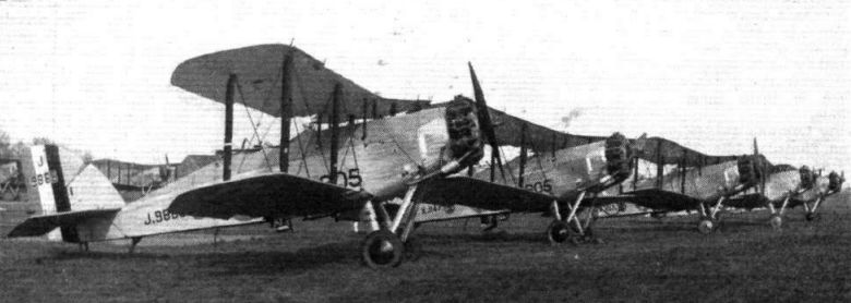
Регистрационный номер: J9868 Самолёты на фотографии: Westland Wapiti - Великобритания - 1927
-

Самолёты на фотографии: Vickers Vildebeest / Type 132 - Великобритания - 1928
-

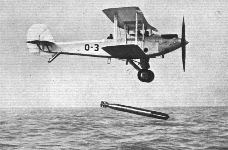
AS A LANDPLANE: View of the "Vildebeest" in the act of dropping its torpedo.
Самолёты на фотографии: Vickers Vildebeest / Type 132 - Великобритания - 1928
-

The photograph gives a good idea of the small amount of spray created by the torpedo on striking the water.
Самолёты на фотографии: Vickers Vildebeest / Type 132 - Великобритания - 1928
-

Регистрационный номер: G-ABGE AS A SEAPLANE: The "Vildebeest" in full flight. The upper photograph shows the machine as a landplane, with the torpedo in place.
Самолёты на фотографии: Vickers Vildebeest / Type 132 - Великобритания - 1928
-

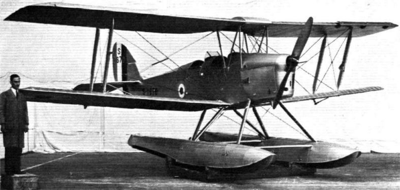
Регистрационный номер: S1676 THE "TIGER MOTH" ON FLOATS: In the description of the De Havilland "Tiger Moth" Training Machine (Gipsy III engine), published in "Flight" of November 13, 1931, we included a side elevation drawing showing the machine fitted with floats and, alternatively, wheels. A set of floats has now been made for it by Short Brothers, and our photograph shows the machine in one of the shops at Stag Lane. It will be seen that the "Tiger Moth" makes quite an attractive-looking seaplane.
Самолёты на фотографии: De Havilland Tiger Moth / D.H.82 - Великобритания - 1931
-

Регистрационный номер: D-2160 The German girl pilot addressing an interested group inside the hangar. Fraulein Beinhorn is now in Sydney, and we understand that she proposes to ship her machine to San Francisco, continuing her journey by air from that point to Pernambuco via Los Angeles, San Diego, Tucson, El Paso, Chihuahua, Mexico City, Guatemala, Nicaragua, Panama, Buenaventura, St. Lorenzo, Quito, Cuenta, Lima, Iquique, Valparaiso, Santiago, Mendoza, Rosario, Buenos Aires, Montevideo, Rio Grande do Sul, Porto Aleere, S. Paulo. Rio de Janeiro, San Salvador, Pernambuco. From that point she will return to Germany by boat.
Самолёты на фотографии: Klemm L.25 - L.28 Swallow - Германия - 1927
-

The picture - for which we are indebted to Shell Mex & B.P., Ltd. - come from Sourabaya, and show Elli Beinhorn's Klemm L.26 (110-h.p. Angus) landing there
Самолёты на фотографии: Klemm L.25 - L.28 Swallow - Германия - 1927
-
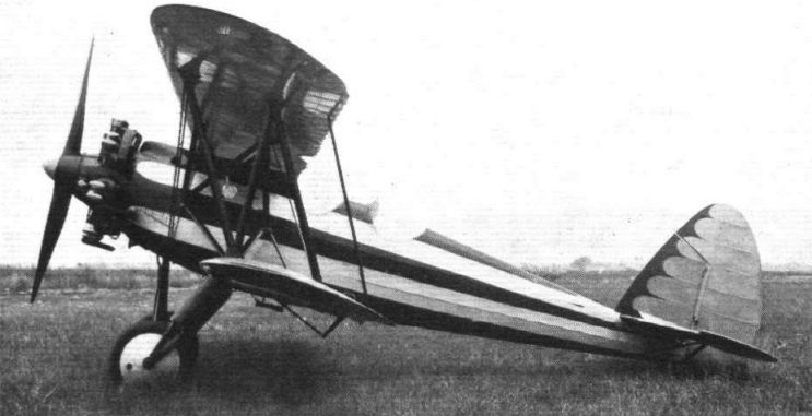
FOR AEROBATICS: The Caproni CA.113, which is fitted with a 240-h.p. Walter air-cooled radial engine.
Самолёты на фотографии: Caproni Ca.113 - Италия - 1931
-
Регистрационный номер: G-ABKG England - Cape Town In 4 1/2 Days: Mollison Realises his Ambition
G-ABKG c/n 2157 became famous as the aircraft in which Jim Mollison, seen here with it, flew from Lympne to Cape Town in record time in 1932 with an extra fuel tank behind the pilot's seat. His telegram to DH on arrival read: "Machine carrying great overload and engine running at nearly maximum revolutions performed magnificently".Самолёты на фотографии: De Havilland Puss Moth / D.H.80 - Великобритания - 1929
-

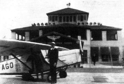
Регистрационный номер: CF-AGO Mr. Nigel Norman leaves Mr. Fred Denslow, manager of the United Airport at Burbank, to face the camera alone. The "Puss Moth" was borrowed from the de Havilland works at Toronto.
Самолёты на фотографии: De Havilland Puss Moth / D.H.80 - Великобритания - 1929
-

The Marconi AD22 light aircraft set installed in a "Puss Moth" air taxi operated by Capt. L. Hope.
Самолёты на фотографии: De Havilland Puss Moth / D.H.80 - Великобритания - 1929
-
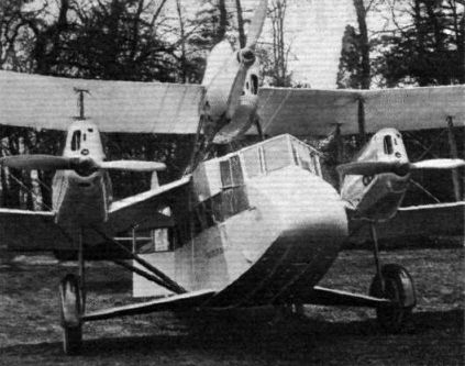
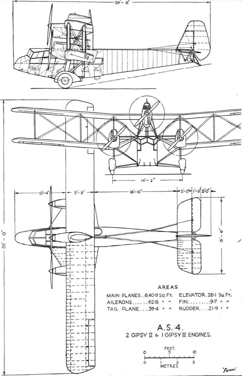
Регистрационный номер: G-ABSI [2] THE "FERRY": Unusual Features are the placing of the central engine, the raising of the lower plane wing roots, and the winglet enclosing the axles and radius rods.
Самолёты на фотографии: Airspeed Ferry / AS.4 - Великобритания - 1932
-
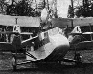
Регистрационный номер: G-ABSI [2] "YOUTH OF BRITAIN II": The first Airspeed "Ferry" poses for its portrait at Hanworth. This machine, which was described in "Flight" of April 15, is a ten-seater to be used by Sir Alan Cobham on his tour of Great Britain. The engines are two Gipsy II's and one Gipsy III.
Самолёты на фотографии: Airspeed Ferry / AS.4 - Великобритания - 1932
-
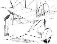
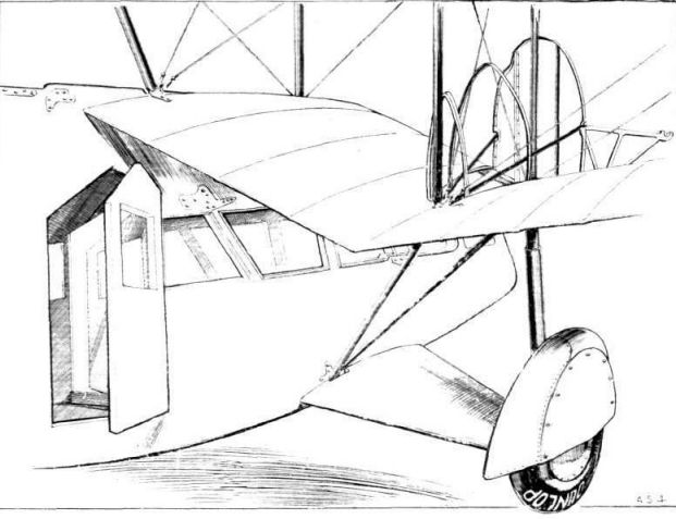
NOVEL FEATURES: The lower plane roots are raised to the top longerons. A winglet encloses the wheel axle and radius rod, and is hinged to the fuselage. The cabin door arrangement, the wing engine mounting, and the "spats" over the wheels are other features illustrated.
Самолёты на фотографии: Airspeed Ferry / AS.4 - Великобритания - 1932
-
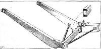
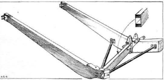
The details of the raised lower wing root are illustrated in this sketch. The spars as well as the compression member are of box section. The wing engine is carried on bearers projecting forward from the front spar.
Самолёты на фотографии: Airspeed Ferry / AS.4 - Великобритания - 1932
-
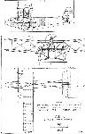
A.S.4 2 Gipsy II & 1 Gipsy III Engines.
Самолёты на фотографии: Airspeed Ferry / AS.4 - Великобритания - 1932
-

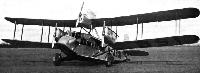
THE BLACKBURN "IRIS V": The machine is taxying slowly with only the outboard engines running.
Самолёты на фотографии: Blackburn Iris / R.B.1 - Великобритания - 1926
-

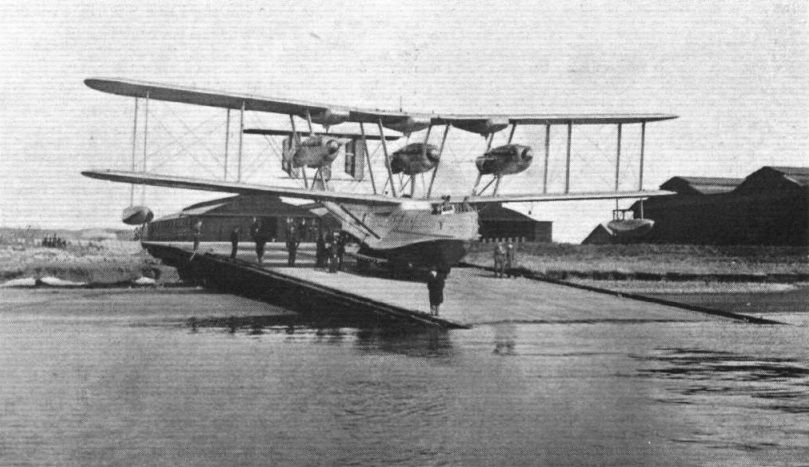
THE BLACKBURN "IRIS V": This photograph shows the machine being launched down the slipway at Brough, her three Rolls-Royce "Buzzard" engines already running.
Самолёты на фотографии: Blackburn Iris / R.B.1 - Великобритания - 1926
-

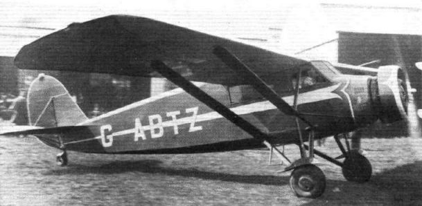
Регистрационный номер: G-ABTZ The Stinson Junior which Mr. Cathcart-Jones is flying round Spain for his employer, Mr. James, is here seen by the N.F.S. workshops at Hanworth.
Самолёты на фотографии: Stinson Detroiter / Junior - США - 1927
-

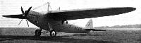
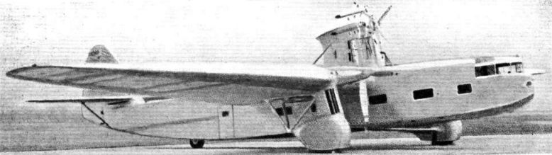
A NEW FORD TYPE: The 14-A is of unusual design and equipped for carrying passengers by night as well as by day. The central engine is a Hispano-Suiza rated at 1,100 h.p., while the wing engines, of the same make, are of 715 h.p. each. The wing engines are housed in the wing, while the central engine is placed in a streamline tower above the wing. The wing span is 110 ft. and the area 1,600 sq. ft. It carries 38 passengers at an estimated cruising speed of 150 m.p.h.
Самолёты на фотографии: Ford 14-AT - США - 1932
-
Регистрационный номер: F-ALCC The Bleriot 110 Zappata monoplane as used by Bossoutrot and Rossi in their recent world's record flight (distance, closed circuit).
Самолёты на фотографии: Bleriot Bleriot-110 Joseph Le Brix - Франция - 1930
-
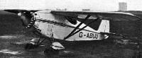
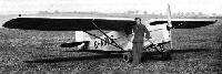
Регистрационный номер: G-ABUU A COMPER "SWIFT" TRAVELLER: Mr. M. Lacayo in the Comper "Swift" (Pobjoy "R" engine) in which he set out from Heston on April 21 on a two months' tour of the Continent to demonstrate the qualities of machine and engine.
Самолёты на фотографии: Comper Swift / CLA.7 - Великобритания - 1930
-

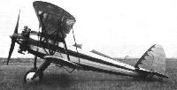
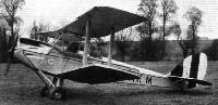
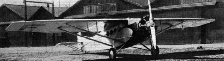
The Farman 190 (240 h.p. Lorraine) on which M. D'Estailleur Chauteraine made a Flight Round Africa.
It was on a similar type of machine to this, fitted with a 300-h.p. Lorraine engine, that Goulette and Salel accomplished their flight from Paris to Cape Town in 3 3/4 days.Самолёты на фотографии: Farman F.190 / F.390 - Франция - 1928
-

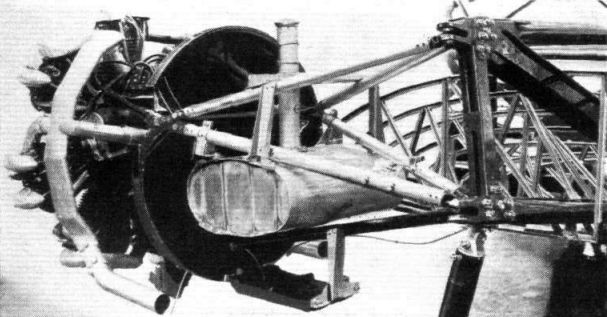
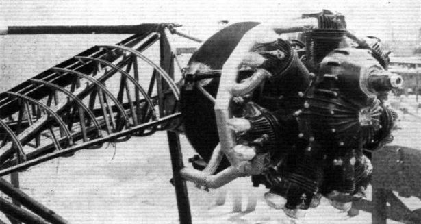
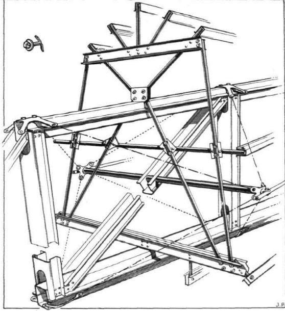
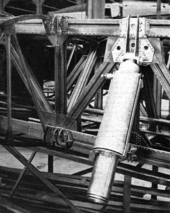
ENGINE SUPPORT: The engine plate proper is carried on four tubes forming a "double wedge," and prevented by a continuation of the leading edge from swinging laterally. Note the oil tank and cooler.
Самолёты на фотографии: General Aircraft Monospar ST-4 - ST-12 - Великобритания - 1932
-

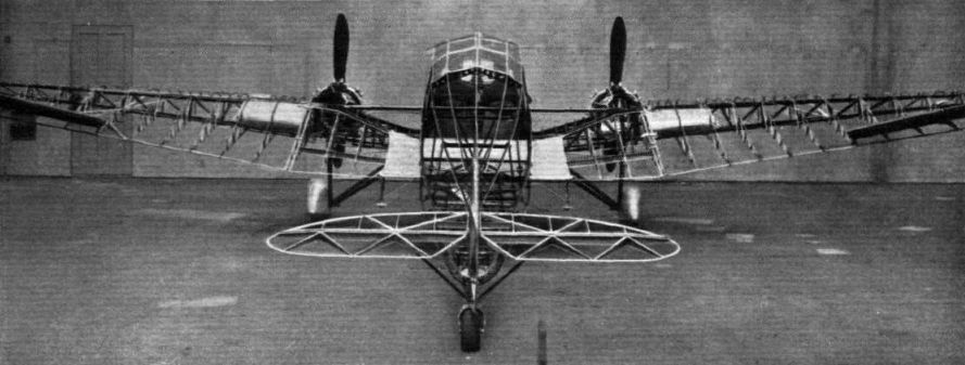
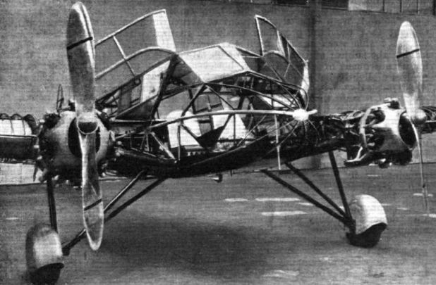
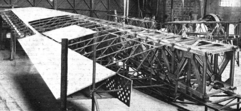
THE POSTERIOR ASPECT: This view, taken from immediately behind, shows wing construction, etc., rather well. Note the placing of the petrol tanks in the wings. The top boom of the wing spar continues right across the fuselage.
Самолёты на фотографии: General Aircraft Monospar ST-4 - ST-12 - Великобритания - 1932
-

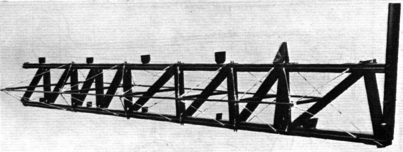
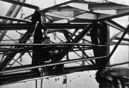
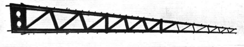
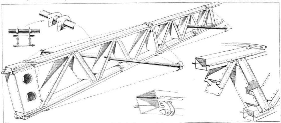
THE FUSELAGE GIRDER: The photograph should be examined in conjunction with the sketches on the next page.
Самолёты на фотографии: General Aircraft Monospar ST-4 - ST-12 - Великобритания - 1932
-

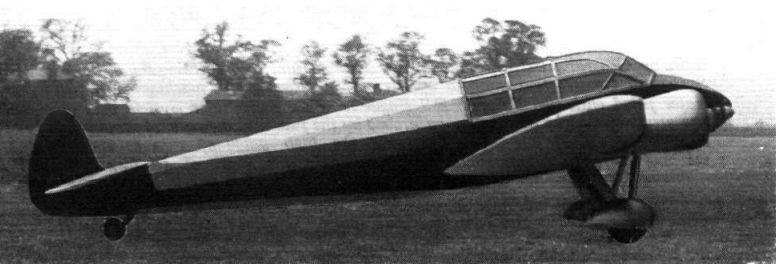
THE BUSINESS PORTION OF THE ST.4: The Pobjoy "R" engines drive Fairey metal airscrews. Note the slimness of the Dowty telescopic legs. The cabin is reached via hinged combined doors and roof.
Самолёты на фотографии: General Aircraft Monospar ST-4 - ST-12 - Великобритания - 1932
-

THE PORT POBJOY Some wing root details may also be seen.
Самолёты на фотографии: General Aircraft Monospar ST-4 - ST-12 - Великобритания - 1932
-

REAR END OF THE FUSELAGE: Details included are the tail-trimming gear and the castoring tail wheel.
Самолёты на фотографии: General Aircraft Monospar ST-4 - ST-12 - Великобритания - 1932
-

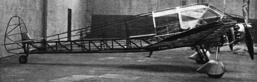
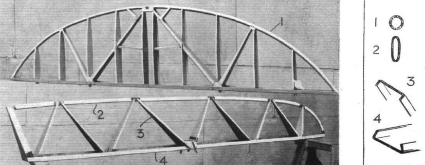
SIDE VIEW OF THE ST.4: The single girder of the fuselage primary structure can be clearly seen. Note also swivelling tail wheel. A corresponding view of the scale model is at the top of the page.
Самолёты на фотографии: General Aircraft Monospar ST-4 - ST-12 - Великобритания - 1932
-

THE SINGLE SPAR: The photograph shows the general arrangement of the shear members
Самолёты на фотографии: General Aircraft Monospar ST-4 - ST-12 - Великобритания - 1932
-

AS IT WILL APPEAR: A composite photograph of a scale model of the ST.4. The actual cowling over the Pobjoy engines will not be of the totally-enclosing type.
Самолёты на фотографии: General Aircraft Monospar ST-4 - ST-12 - Великобритания - 1932
-

Самолёты на фотографии: General Aircraft Monospar ST-4 - ST-12 - Великобритания - 1932
-

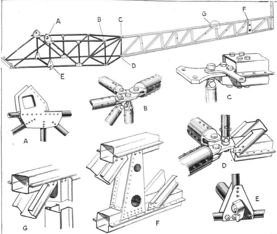
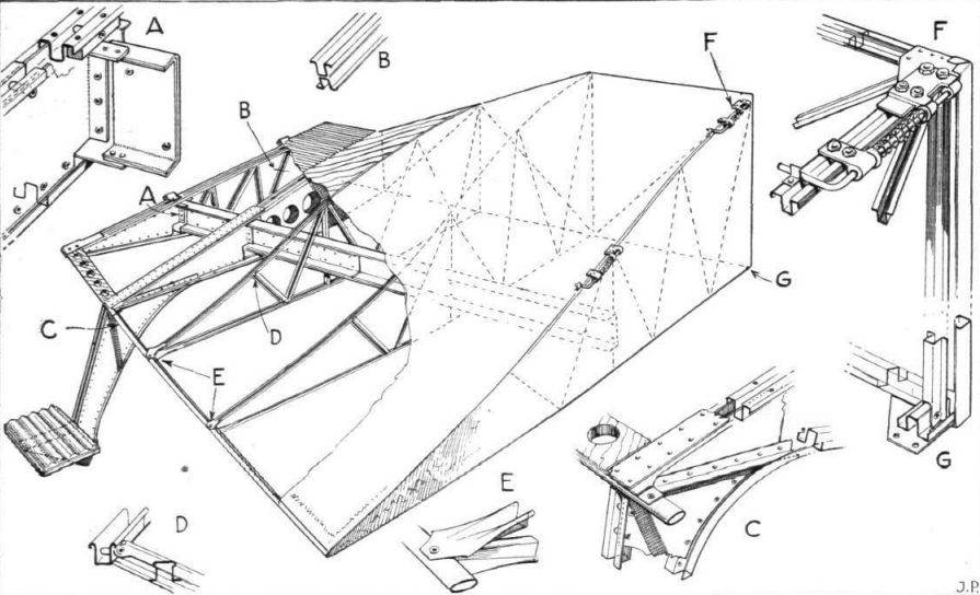
THE PRIMARY STRUCTURE OF THE FUSELAGE: The key diagram gives the locations of the details. The torsion bracing has been omitted.
Самолёты на фотографии: General Aircraft Monospar ST-4 - ST-12 - Великобритания - 1932
-

ON THE ST.4: The trailing portion of the wing roots hinges up alongside the fuselage to allow of folding the wings. It is in this portion of the wing that the lifting of the trailing edge occurs, the object being to reduce interference drag. A step on the trailing edge facilitates getting into and out of the cabin.
Самолёты на фотографии: General Aircraft Monospar ST-4 - ST-12 - Великобритания - 1932
-

TAILPLANE AND AILERON: The tailplane is shown in the upper photograph and an aileron in the lower. Details of the various members are shown on the right.
Самолёты на фотографии: General Aircraft Monospar ST-4 - ST-12 - Великобритания - 1932
-

THE SINGLE SPAR: The sketches illustrate structural details. The small sketch at the bottom shows the rib-supporting brackets.
Самолёты на фотографии: General Aircraft Monospar ST-4 - ST-12 - Великобритания - 1932
-

THE FUSELAGE GIRDER: Sketch shows the details of the girder and the torsion bracing, etc.
Самолёты на фотографии: General Aircraft Monospar ST-4 - ST-12 - Великобритания - 1932
-

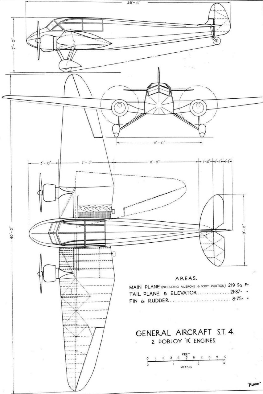
General Aircraft ST.4 2 Pobjoy "R" Engines
Самолёты на фотографии: General Aircraft Monospar ST-4 - ST-12 - Великобритания - 1932
-

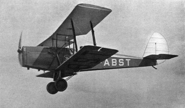
Регистрационный номер: G-ABST FLIGHT-TESTING THE NEW NAPIER ENGINE: The first of these engines (6-cylinder in line air cooled, 150 h.p.) has been built into a "Spartan" aeroplane for the purpose of extensive flying tests. The machine is likely to visit, during the test period, several British aerodromes, and readers are advised to bear in mind the registration letters G-ABST. By way of mnemonic assistance we would suggest British Summer Time.
Самолёты на фотографии: Spartan Arrow - Великобритания - 1930
-

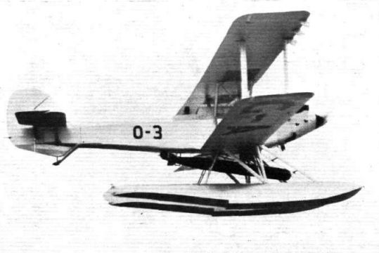
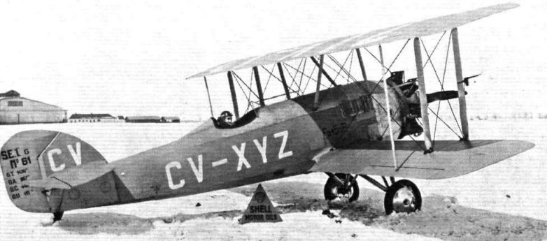
Регистрационный номер: CV-XYZ A ROUMANIAN VENTURE: The S.E.T. 61 on which Prince Ghica is attempting a record flight from Bucharest to Saigon, Indo China.
SET-31G, a modified series production aircraft with additional fuel tanks. It was in this aircraft that Ionel Ghica flew from Bucharest to China and back.Самолёты на фотографии: SET SET 3 / 31 / 4 / 41 - Румыния - 1928
-
FOR SMOOTH LANDINGS: A "Moth" (Gipsy) belonging to Eastern Air Transport, Ltd., which is used at the Skegness Aero Club. This firm know the damage which pupils may cause an aircraft by heavy landings and they have therefore wisely obviated this as far as possible by fitting Goodyear Airwheels.
Самолёты на фотографии: De Havilland Gipsy Moth / Moth X - Великобритания - 1928
-

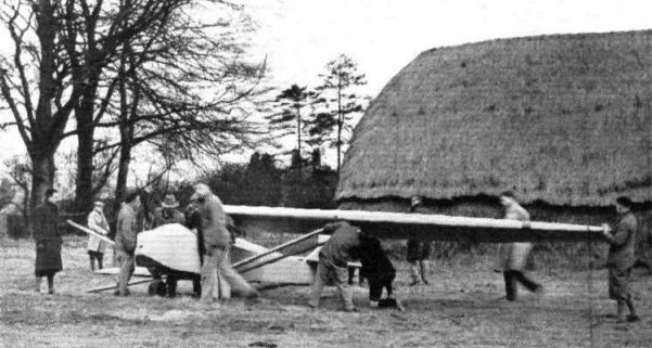
AT DUNSTABLE: Erecting the B.A.C.VII in a field near Dunstable preparatory to doing some auto-towed gliding during the Easter holidays.
Самолёты на фотографии: Lowe-Wylde Columbus / BAC.II - BAC.IX - Великобритания - 1930
-

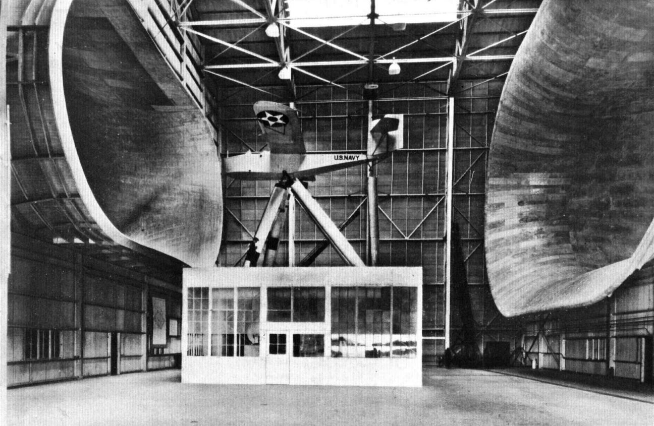
THE AMERICAN COUNTERPART: The full-scale wind tunnel at Langley Laboratory gives an air stream 60 ft. wide by 30 ft. high. One of the 35-ft. diameter four-bladed airscrews can be seen. It is driven by an electric motor of 4,000 h.p. The aircraft is supported on a six-component balance.
Самолёты на фотографии: Loening SL - США - 1931
-

FULL SCALE RESEARCH: This photograph of the new large wind tunnel at Langley Field, Virginia, has been very kindly lent to us by Mr. John J. Ide, Technical Assistant in Europe of the American N.A.C.A. The tunnel is of the open type, and the aeroplane is supported on a six-component balance by means of struts in the centre of an airstream 60 ft. wide and 30 ft. high. The four-bladed propellers which circulate the air are of 35 1/2 ft. diameter, and each is driven by an electric motor of 4,000 h.p. the high figure of 112 m.p.h. The machine under test is a Loening flying boat.
Самолёты на фотографии: Loening SL - США - 1931
-

Самолёты на фотографии: Breda Ba.32 - Италия - 1931
-

THE BREDA 32 WING: A general view of the port wing, showing single spar, ribs, skin, etc. The four pipe unions by which the wing is attached to the wing root are seen at the right-hand extremity of the picture.
Самолёты на фотографии: Breda Ba.32 - Италия - 1931
-

DETAILS OF WING AND UNDERCARRIAGE: This photograph gives a good idea of the construction of the single spar, which is a girder built up of box-section booms and struts. The telescopic leg of the undercarriage is attached to the spar, and housed inside the wing. The other lugs seen are for the support of the engine mounting.
Самолёты на фотографии: Breda Ba.32 - Италия - 1931
-

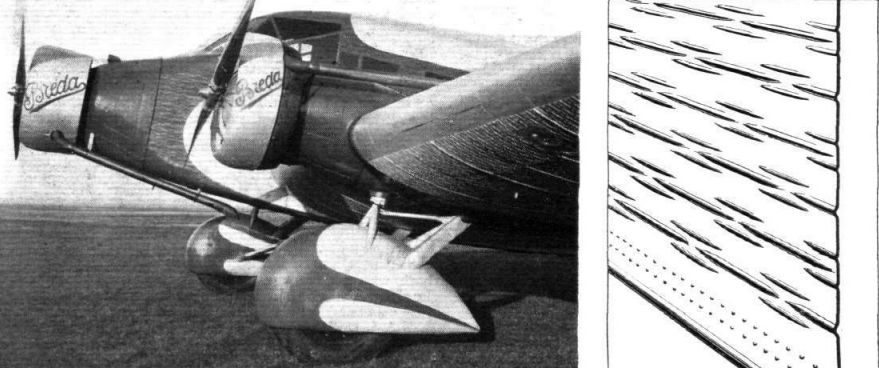
CAREFUL FAIRING: The wing engines of the Breda 32 are well cowled in, and the undercarriage has been streamlined by "spats" rigidly fixed to, and moving with, the wheel. On the right is a sketch showing how the metal skin is stiffened by "blisters."
Самолёты на фотографии: Breda Ba.32 - Италия - 1931
-
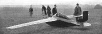
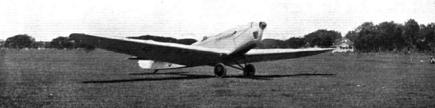
OF BIRD-LIKE PROPORTIONS: A three-quarter rear view of the Nyborg sailplane. The designer is standing by the right-hand wing tip and his assistant, Mr. H. Green, is in front. The dimensions are :- Area, 45 sq. ft.; span, 32 ft.; chord, 16 in.; weight, 370 lb., including 150 lb. for the pilot; the gliding angle at 57 m.p.h., according to Mr. Nyborg's calculations, should be about 1 : 54. The large rudder is being used temporarily for auto-towing, and if possible will later be discarded for a much smaller one which will be assisted in obtaining directional control by two small drag-producing flaps under each wing-tip. The trailing edge of the wing inside the aileron is divided into three flaps on each side which can be used for increasing the effective camber and as air brakes.
Самолёты на фотографии: Nyborg TGN-1 - Великобритания - 1932
-
HIGH ASPECT RATIO: A front view of the Nyborg sailplane which gives a good idea of its narrow chord wings. Mr. T. G. Nyborg is on the left, Mr. H. Green on the right, and the pilot in the cockpit is Mr. L. C. Williams. The wing spar is a solid 4 in. by 3 in. spruce beam tapered from the root and the wing is plywood covered. To obtain his design Mr. Nyborg has scaled up the best soaring birds, thus his sailplane has the same loading and dimensions one would expect, say, an albatross of the same weight to have.
Самолёты на фотографии: Nyborg TGN-1 - Великобритания - 1932


Статьи
- Flight