

Описание
 Wiki
Wiki 
Страна : Великобритания
Год : 1930
Ночной бомбардировщик с экипажем из четырех человек
Handley Page H.P.38 и H.P.50 Heyford
H.P.50 Heyford представлял собой самолет с бипланной конструкцией, выглядевшей достаточно массивно, и основными опорами шасси, имевшими стойки с обтекателями, что в целом наводило на мысль о его низкой скорости и малой эффективности. Это впечатление усиливалось тем, что фюзеляж был установлен под верхним крылом, а большой промежуток между фюзеляжем и нижним крылом заполняли стойки. Такая компоновка преследовала определенную цель: центральная часть нижнего крыла имела почти вдвое большую по сравнению с остальными машинами того времени толщину, позволявшую разместить там существенную бомбовую нагрузку, к тому же на расположенные близко к земле держатели легче было подвешивать бомбы. Еще одной отличительной особенностью самолета было расположение трех пулеметов - один из них размещался в специальной подфюзеляжной турели, которая могла опускаться под фюзеляжем, позади крыла. Прототип H.P.38 совершил первый полет 12 июня 1930 года, а последующие успешные результаты опытной эксплуатации машины привели к заказу ВВС крупной партии самолетов, получивших первоначально обозначение Heyford Mk I. Всего же ВВС получили 124 самолета (15 Heyford Mk I, 23 Heyford Mk IA, 16 Heyford Mk II и 70 Heyford Mk III), выпуск их был прекращен в июле 1936 года. Модификации поставлявшихся самолетов отличались преимущественно силовой установкой: Mk I оснащались двигателями Kestrel III, машины Mk II и Mk III - двигателями Kestrel VI мощностью 640 л.с., хотя были и другие отличия - четырех-, а не двухлопастные воздушные винты, крыльевой радиатор, модифицированное крепление двигателей на модели Mk III и пр. Самолеты поступили на вооружение 99-й эскадрильи, дислоцированной в Верхнем Хейфорде, графство Оксфордшир, в ноябре 1933 года. Впоследствии самолеты Heyford поступили на вооружение 7-й, 9-й, 10-й, 38-й, 78-й, 97-й, 102-й, 148-й, 149-й и 166-й эскадрилий. Последние из них были сняты с вооружения в 1939 году в связи с заменой на бомбардировщики-монопланы Vickers Wellington. Heyford продолжал эксплуатироваться некоторое время в учебных подразделениях, пока окончательно не был списан в июле 1941 года.
ТАКТИКО-ТЕХНИЧЕСКИЕ ХАРАКТЕРИСТИКИ
Handley Page Heyford Mk IA
Тип: ночной бомбардировщик с экипажем из четырех человек
Силовая установка: два V-образных ПД Rolls-Royce Kestrel IIIS или IIIS-5 мощностью по 575 л. с. (429 кВт)
Летные характеристики: максимальная скорость на высоте 3960 м - 229 км/ч; крейсерская скорость на высоте 3050 м - 185 км/ч; набор высоты 3050 м - за 15 мин 18 с; практический потолок 6400 м; дальность полета 644 км - с бомбовой нагрузкой 1426 кг
Масса: пустого 4173 кг, максимальная взлетная 7666 кг
Размеры: размах крыльев бипланной коробки 22,86 м; длина 17,68 м; высота 5,33 м; площадь крыльев 136,56 м2
Вооружение: один 7,7-мм наводимый пулемет Lewis в носовой части фюзеляжа, по одному 7,7-мм наводимому пулемету Lewis для обороны задней полусферы - в надфюзеляжной и выдвижной подфюзеляжной установках, плюс до 1588 кг бомб в отсеке в нижнем крыле и на восьми подкрыльевых узлах подвески
Описание:
- Handley Page H.P.38 и H.P.50 Heyford
- Flight, July 1933
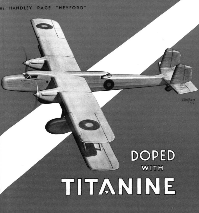
THE HANDLEY PAGE "HEYFORD" - Flight, June 1934
Handley-Page "Heyford" Mark II
Фотографии

-

Aeroplane Monthly 1984-10 / P.Jarrett - The rarest Stampe of all
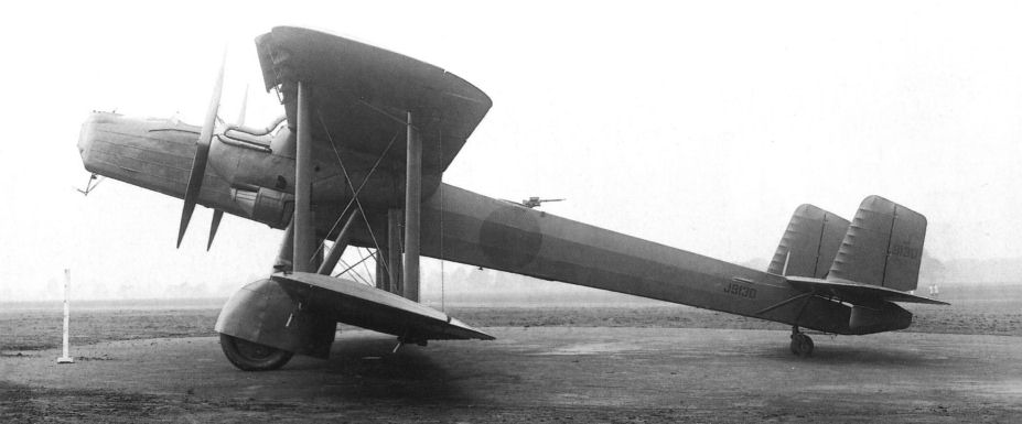
Регистрационный номер: J9130 [14] The prototype Heyford, J9130.
-

Air Enthusiast 2003-03 / B.Dunn - Half-way house
Регистрационный номер: J9130 [14] The prototype HP.38, J9130. Note the 20lb practice bombs under the trailing edge of the rear wing - these gave clearance problems at the A&AEE.
-

Air-Britain Aeromilitaria 1994-01 / Handley Page Heyford
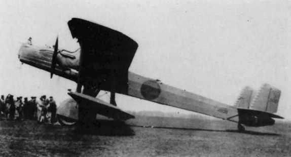
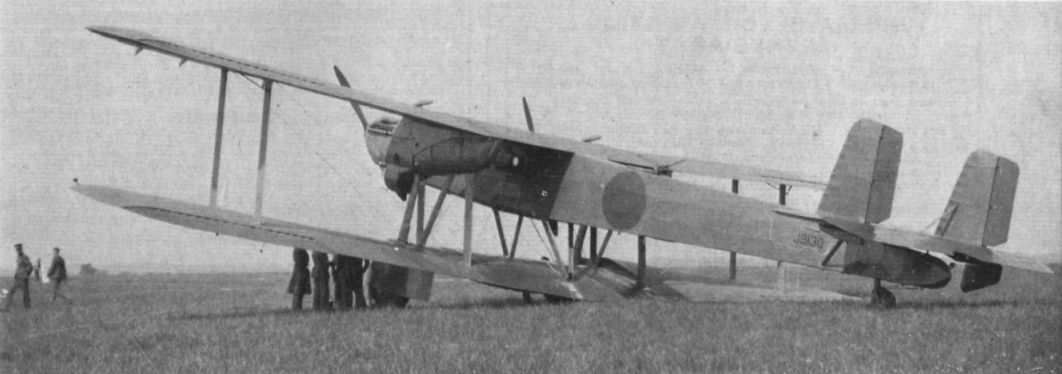
Регистрационный номер: J9130 [14] J9130 creates interest on a visit to Upavon
-

Aeroplane Monthly 1976-07 / Personal album
Регистрационный номер: J9130 [14] The Handley Page HP38 J9130 was the prototype Heyford, and is seen at Upper Heyford after an undercarriage collapse on June 10, 1932. It was repaired, only to be destroyed on July 10 when it crashed and burst into flames at North Coates, the crew escaping unharmed.
-

Air Enthusiast 2003-03 / B.Dunn - Half-way house
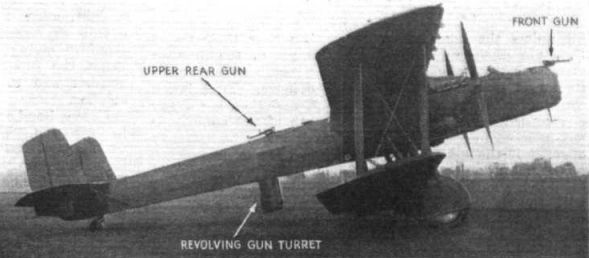
Регистрационный номер: J9130 [14] Another view of the HP.38 showing the upper turret and the 'dustbin' in lowered position.
-

Air-Britain Aeromilitaria 1982-03 / Royal Air Force January 1939
Heyford of No.149 Squadron
-

Aeroplane Monthly 1984-09 / A.Lumsden, T.Heffernan - Probe Probare (6)
Регистрационный номер: J9130 [14] The Heyford prototype, J9130, pictured at Radlett. It was first flown on June 12, 1930 by Maj Jim Cordes for five minutes. A second flight of ten minutes followed later the same day. The nose gunner has not just hijacked the pilot!
-

Flight 1935-08 / Flight
The Handley Page "Heyford" heavy bomber has one gun position in the nose, a second gun above the fuselage behind the wings, and a revolving turret which can be lowered underneath the fuselage. It would be difficult to find a blind spot.
-

-

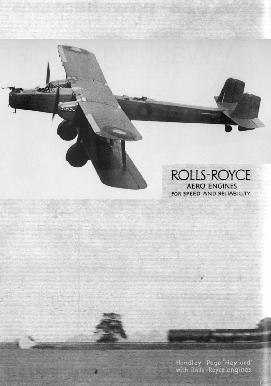
Flight 1935-03 / Flight Advertisements
Handley Page "Heyford"
-
Air-Britain Aeromilitaria 1994-01 / Handley Page Heyford
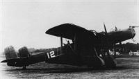
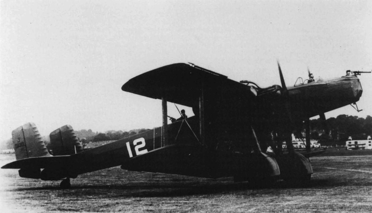
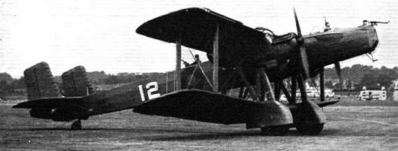
Регистрационный номер: J9130 [14] Prototype Heyford J9130 carries the New Types number 12 at the Royal Air Force Pageant in June 1932
-

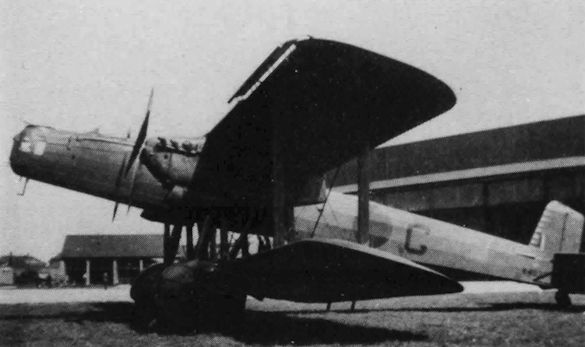
Flight 1932-07 / Flight
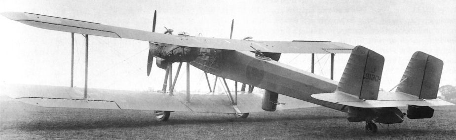
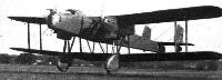
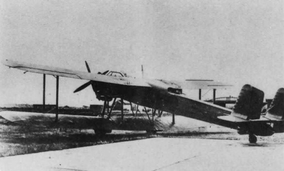
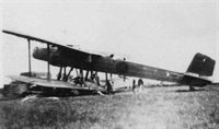
Регистрационный номер: J9130 [14] UNORTHODOXY: The Handley Page 38 Night Bomber (two "Kestrel") has fuselage and engines placed under the upper wing.
-

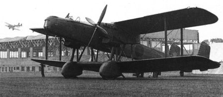
Flight 1934-02 / Flight
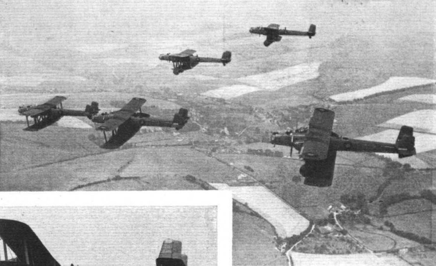
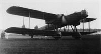
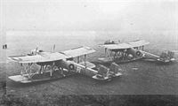
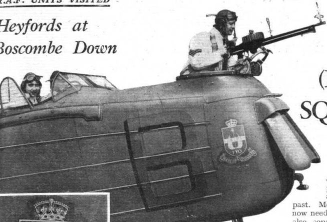
"HEYFORDS" FOR HEYFORD: View of the Handley Page "Heyford" night bombers just delivered to No. 99 (Bomber) Squadron, Upper Heyford.
-

Aeroplane Monthly 1984-09 / A.Lumsden, T.Heffernan - Probe Probare (6)
Регистрационный номер: K3489 [10] Heyford K3489 spent the early part of its life with the A&AEE and the RAE before transferring to 149 Squadron.
-
Air-Britain Aeromilitaria 1994-01 / Handley Page Heyford
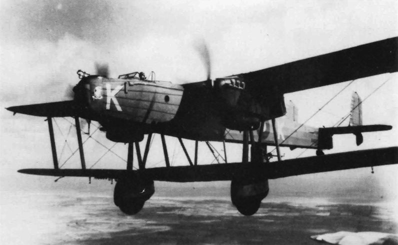
Регистрационный номер: K4023 [2] K4023, K of No. 10 Squadron, at Boscombe Down
-

Aeroplane Monthly 1990-11 / Personal album. Military
Регистрационный номер: K3500 [7] An unidentified Handley Page Heyford heavy night bomber. The type entered service with the RAF in November 1933, with 99 Squadron at RAF Upper Heyford, and was the last of the RAF's biplane heavy bombers. The aircraft seen here is probably K3500 of 99 Squadron, based at Upper Heyford and later at Mildenhall, which crashed during night-flying on May 21, 1937.
-

Flight 1939-06 / Flight
Регистрационный номер: J9130 [14] Of unusual conception was the Heyford - two Rolls-Royce F (Kestrel) engines - with its fuselage placed directly under the top wing.
-
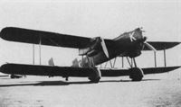
Flight 1934-06 / Flight
Handley Page "Heyford" (two "Kestrel" III.MS).
-

Air Enthusiast 2003-03 / B.Dunn - Half-way house
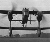
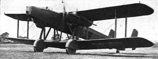
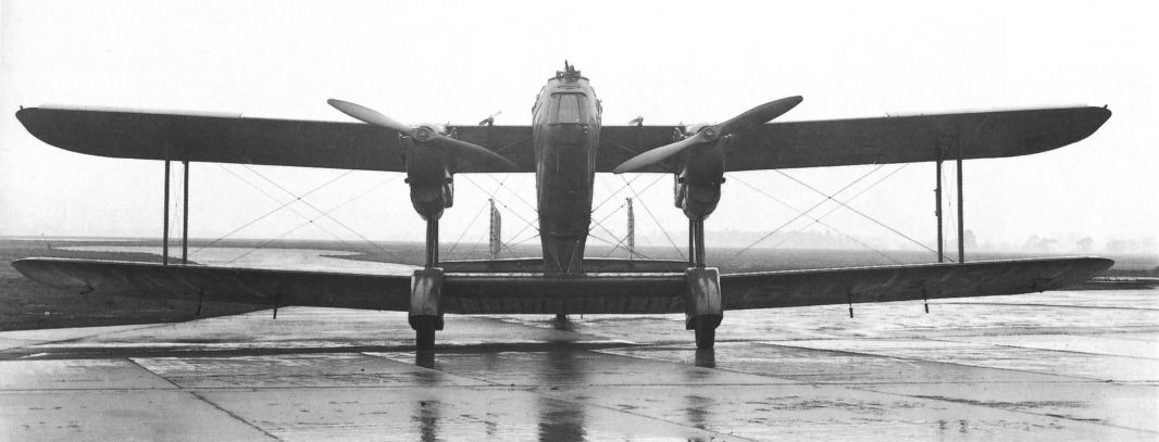
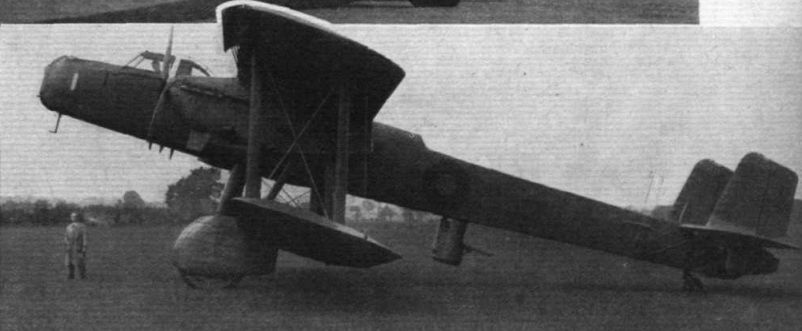
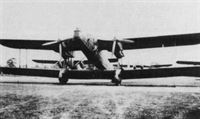
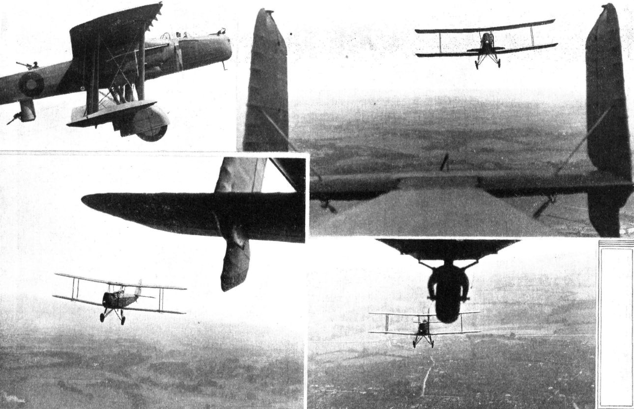
Регистрационный номер: K3489 [10] Front view of the first production Heyford, K3489. In between the mainwheels can just be discerned the bomb cells in the lower wing centre section.
-
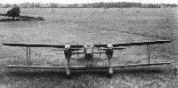
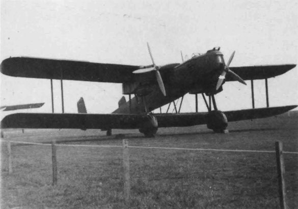
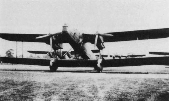
Flight 1933-07 / Flight
"NOSE-ON": This front view gives a good idea of the small frontal area of the "Heyford."
-
Aeroplane Monthly 1996-05 / M.Rowe - Cameras in the sky
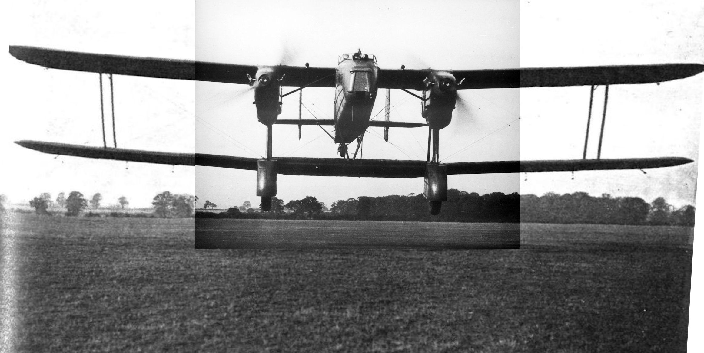
Регистрационный номер: K3489 [10] A worm's-eye view of Handley Page Heyford K3489, its pilot. Maj Cordes, doing his best to eliminate Flight photographer John Yoxall at Radlett on November 25, 1933.
-

Aeroplane Monthly 1977-10
Регистрационный номер: K3489 [10] READY FOR MARTLESHAM: The first production model of the Handley Page "Heyford" bombers (Rolls-Royce "Kestrel" engines) was completed last week, and after constructor's trials was flown to Martlesham for official trials. Our photographer did not stand in a pit dug in the aerodrome when he took the head-on view. The pilot was Sqd. Ldr. T. H. England.
Our dramatic photograph, depicting Squadron Leader T. H. England flying Handley Page Heyford I K3489, was taken by John Yoxall of Flight on October 19, 1933.
Cordes points the H.P.38 J9130 at Flight’s photographer at Radlett in July 1931. -

Aeroplane Monthly 1981-02 / Radlett /Gone but not forgotten/ (9)
Регистрационный номер: K3489 [10] First production H.P.50 Heyford 1, K3489, photographed at Radlett on October 19, 1933 with Sqn Ldr T. H. England at the controls. The type was to enter service in November 1933.
-
Air-Britain Aeromilitaria 1994-01 / Handley Page Heyford
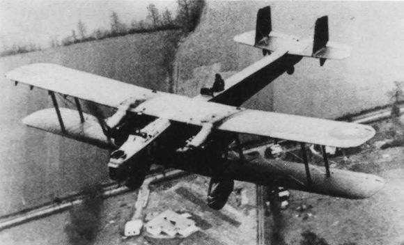
Регистрационный номер: J9130 [14] Крылья Heyford имели металлическую конструкцию с полотняной обшивкой, фюзеляж - металлический с обшивкой из легкого сплава и полотна, экипаж - четыре человека, шасси - неубирающееся с хвостовым колесом.
THE HANDLEY PAGE H.P. 38: This machine, produced two years ago, is still surrounded with a certain amount of secrecy. It is a night bomber with high performance, and the arrangement of the fuselage and engines is such as to provide monoplane view while retaining biplane manoeuvrability. Wing span 75 ft. Gross weight 15,600 lb. The H.P. 38 will be seen at Hendon on June 25.
Prototype J9130 flies past at Radlett in 1932.
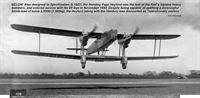
Also designed to Specification B.19/27, the Handley Page Heyford was the last of the RAF’s biplane heavy bombers, and entered service with No 99 Sqn in November 1933. Despite being capable of uplifting a meaningful bomb-load of some 3,500lb (1,585kg), the Heyford (along with the Hendon) was discounted as “operationally useless”. -

Aeroplane Monthly 1995-12 / P.Jarrett - Handley Page Heyford /By day and by night/
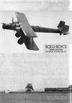
Регистрационный номер: K3489 [10] The first production Heyford Mk I, K3489, takes off from the manufacturer’s aerodrome at Radlett, Hertfordshire, in 1933.
-

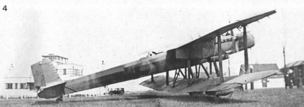
Flight 1930-07 / Flight
Регистрационный номер: J9130 [14] THE LATEST HANDLEY-PAGE NIGHT BOMBER: The engines are Rolls-Royce "F" type. Note the placing of the fuselage under the top plane.
-

Air-Britain Aeromilitaria 1994-01 / Handley Page Heyford
Регистрационный номер: K4024 K4024, C of No. 10 Squadron
-

Jane's All the World Aircraft 1980 / Encyclopedia of Aviation - Aircraft A-Z - v3
Handley Page Heyford Mk IA.
-
Flight 1936-06 / Flight
" ... guns firing downwards from positions in the floor of the fuselage." (The Heyford and its "dustbin.")
-

Flight 1936-09 / Flight
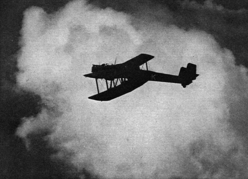
Study in light and shade: a Heyford of No. 102 (B.) Squadron on its way from Worthy Down to Finningley during the recent move to the new aerodrome.
-

Aeroplane Monthly 1995-12 / P.Jarrett - Handley Page Heyford /By day and by night/
Регистрационный номер: K3489 [10] Another study of the first production Heyford Mk I, K3489, during a press demonstration in mid-1933, shortly after completion. The lowered rear upper gunner’s windshield is clearly visible.
-

Aeroplane Monthly 1984-09 / A.Lumsden, T.Heffernan - Probe Probare (6)
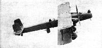
Регистрационный номер: K3500 [7] Another view of the 99 Squadron Heyford K3500, showing the dustbin turret extended.
-

Flight 1935-05 / Flight
Регистрационный номер: K3500 [7] EFFICIENT DISTRIBUTION OF ARMAMENT. On the Handley Page "Heyford" Night Bomber one gun is carried in the nose and two midway between the wings and tail. Of these, one is mounted in the "dustbin" seen extended.
-

Air-Britain Aeromilitaria 1994-01 / Handley Page Heyford
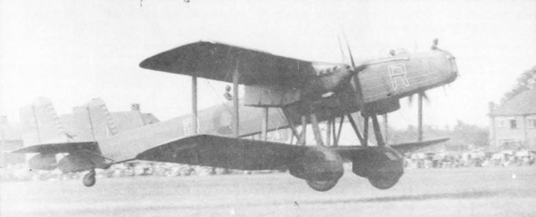
Регистрационный номер: K3500 [7] A well-known shot of Heyford I K3500 of No.99 Squadron which shows the eccentric design of this type to advantage.
Mk.I K3500 of 99 Squadron with its gunners taking exception to the photo-ship! Delivered in March 1934, it crashed near Colchester in May 1937. -
Aeroplane Monthly 1974-05 / Handley Page Heyford /Press Debut/
READY FOR MARTLESHAM: The first production model of the Handley Page "Heyford" bombers (Rolls-Royce "Kestrel" engines) was completed last week, and after constructor's trials was flown to Martlesham for official trials.
-

Aeroplane Monthly 1995-12 / P.Jarrett - Handley Page Heyford /By day and by night/
Регистрационный номер: J9130 [14] J9130, the H.P.38 prototype, cavorts for Flight’s photographer at Radlett in May 1931. Numerous changes were incorporated in the production H.P.50.
-

Air-Britain Aeromilitaria 1994-01 / Handley Page Heyford
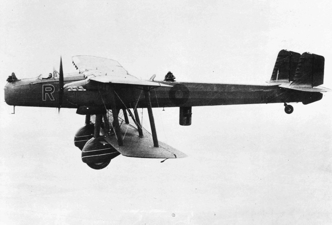
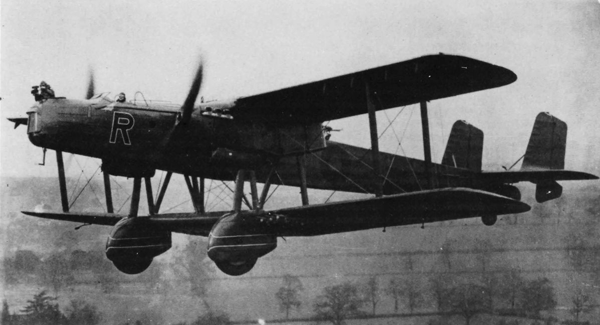
Регистрационный номер: K3500 [7] K3500, R of No. 99 Squadron, with a cine-camera mounted in the nose. Note the propeller guards beside the cockpit
-

Aeroplane Monthly 1984-09 / A.Lumsden, T.Heffernan - Probe Probare (6)
Регистрационный номер: K3500 [7] Heyford I K3500 of 99 Sqn. This aircraft crashed following an engine failure at night on May 21, 1937.
-

Air-Britain Aeromilitaria 1994-01 / Handley Page Heyford
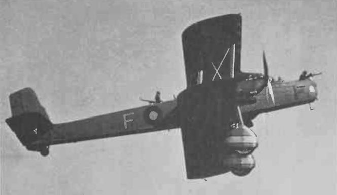
Регистрационный номер: K4023 [2] Heyford K4023, K of No. 10 Squadron, with dustbin down.
-
Air-Britain Aeromilitaria 1994-01 / Handley Page Heyford
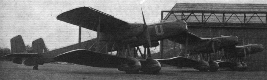
Регистрационный номер: K3493 K3493, U of No. 99 Squadron
-

Aeroplane Monthly 1987-06 / Farewell Hendon again
102 Sqn Heyfords at the 1936 Display.
A view of the Heyfords from the two-shilling enclosures. -

Flight 1935-08 / Flight
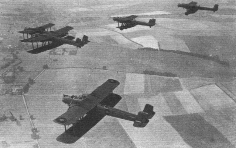
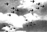
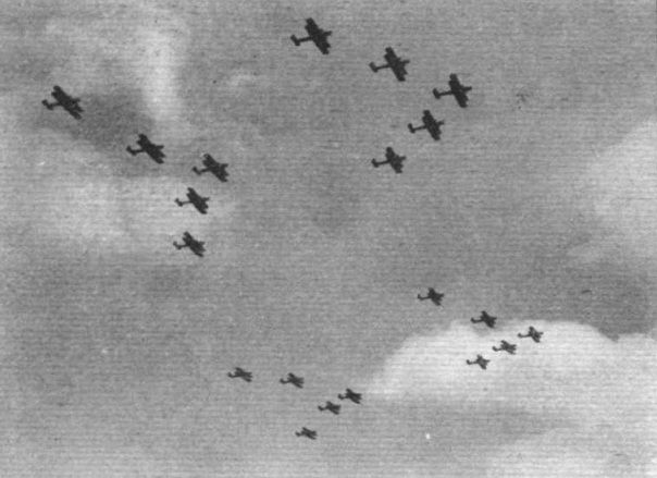
No. 10 (BOMBER) SQUADRON. A flight of five Handley-Page "Heyfords" flying in formation by day. Last week the squadron made night raids on Portsmouth and was very successful in evading the searchlights.
-

-

Aeroplane Monthly 1984-09 / A.Lumsden, T.Heffernan - Probe Probare (6)
A formation of Heyfords of 105 Squadron photographed in July 1935. Nos 10 and 99 Squadrons were the first units to receive the Heyford and 11 squadrons operated the type between 1933 and 1939.
-

Flight 1936-09 / Flight
Farewell to Worthy Down: Heyfords on the way to their new home at Finningley
-

Flight 1936-07 / Flight
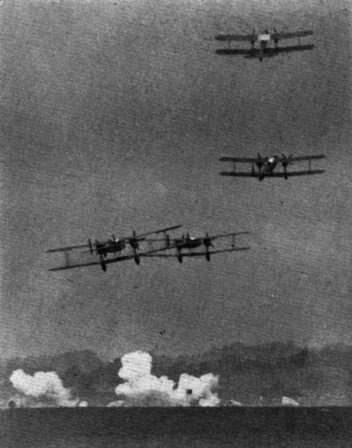
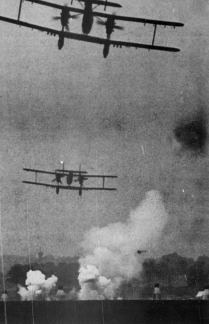
The leading Heyford zooms after making its shot at the skittles. Two bombs can just be discerned falling from another machine
-

Aeroplane Monthly 1974-09 / ??? - Hendon Pageantry 1920-37
Handley Page Heyfords skittle bombing at the 1936 pageant.
-

Flight 1934-02 / Flight
"HEYFORDS" FOR HEYFORD: View of the Handley Page "Heyford" night bombers just delivered to No. 99 (Bomber) Squadron, Upper Heyford.
-

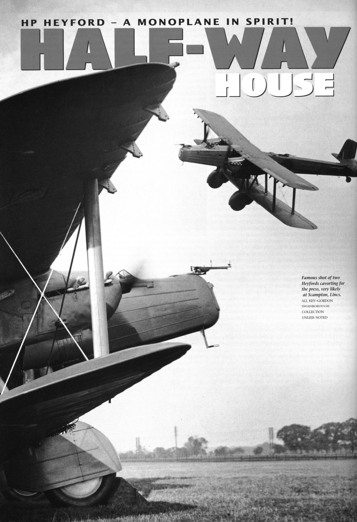
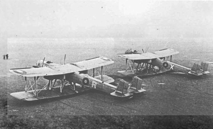
Air Enthusiast 2003-03 / B.Dunn - Half-way house
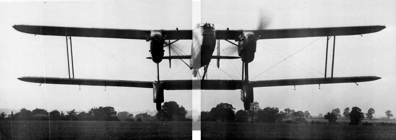
Famous shot of two Heyfords cavorting for the press, very likely at Scampton, Lincs.
-

Aeroplane Monthly 1982-12 / Hanworth /Gone but not forgotten/ (14)
Регистрационный номер: K6889 [2] The H.P.Heyford K6889 arrives at the 1937 Empire Air Day.
-

Flight 1936-09 / Flight
What is the weather in three hours' time?
-

Flight 1934-02 / Flight
"HEYFORDS" FOR HEYFORD: View of the Handley Page "Heyford" night bombers just delivered to No. 99 (Bomber) Squadron, Upper Heyford.


-

Air-Britain Aeromilitaria 1994-01 / Handley Page Heyford
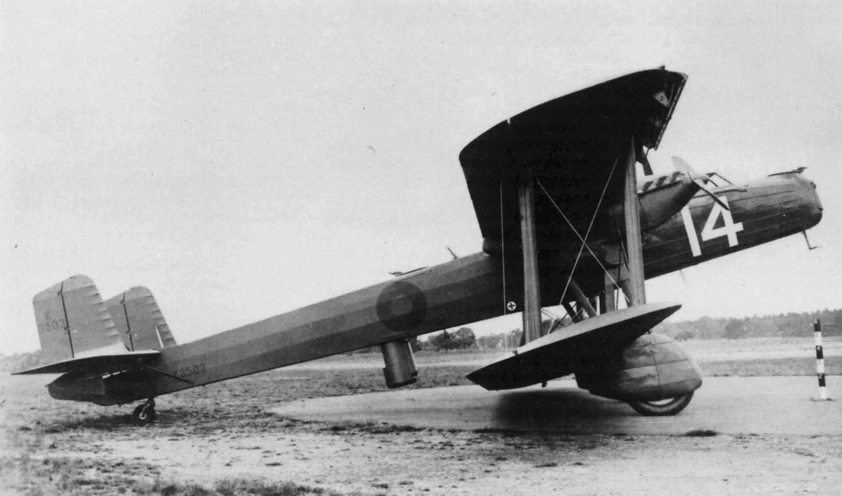
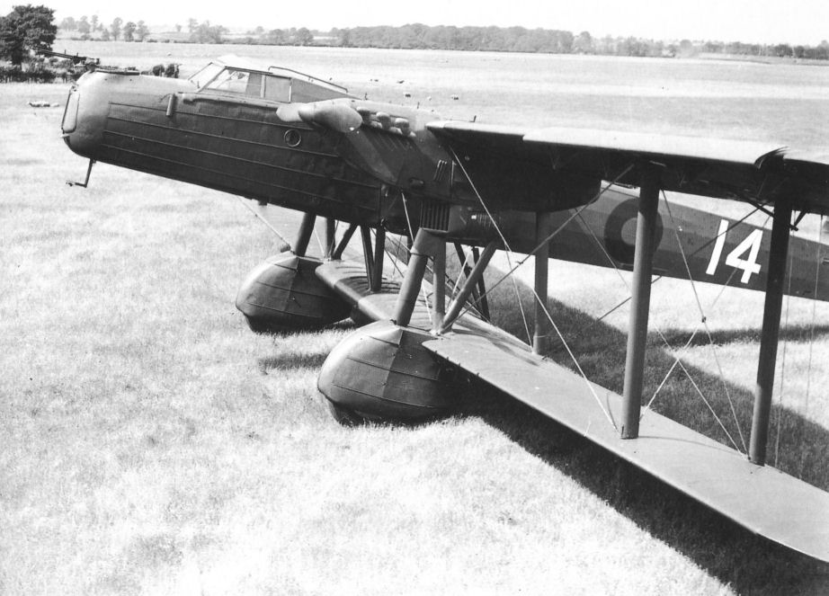
Регистрационный номер: K3503 [2] K3503 acted as the prototype Heyford II with cabin. The "14" in its New Types Park number for the 1934 RAF Pageant
-

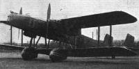
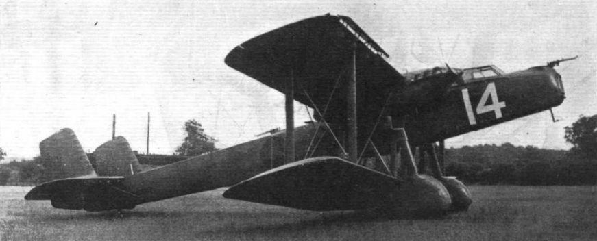
Flight 1934-06 / Flight
Handley Page "Heyford," Mark II (two Rolls-Royce "Kestrel" engines).
-

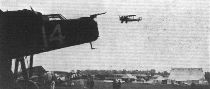
Flight 1934-07 / Flight
NIGHT BOMBER AND TRANSPORT TYPES: In the foreground the nose of the Handley Page "Heyford." Flying past is the Vickers "Vellox."
Другие самолёты на фотографии: Vickers Vellore / Vellox - Великобритания - 1928
-

Air-Britain Aeromilitaria 1994-01 / Handley Page Heyford
Регистрационный номер: K4029 K4029, X of 166 Squadron, shows modified gun position on Mk.IIA
-

Air Enthusiast 2003-03 / B.Dunn - Half-way house
Регистрационный номер: K3503 [2] Heyford K3503 was used by HP for a series of improvements, including Kestrel VIs and an enclosed cockpit. It is wearing the Hendon 'new types park' number '14' for the 1934 Air Pageant.
-

Flight 1935-12 / Flight
The Handley Page Heyford fitted with 600 h.p. Kestrel VI's.
-

Flight 1939-06 / Flight
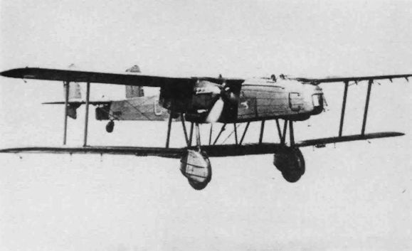
MORE COMFORT AND PERFORMANCE: An improved version of the Mk. II Handley Page "Heyford" heavy bomber. Points to notice are the enclosed pilots' cockpit, four-bladed airscrews, which are driven by fully supercharged "Kestrels VI" engines of 600 h.p. in streamlined nacelles, and the bomb-aimer's position. The rear gunner's cockpit has also been modified.
-
Flight 1936-01 / Flight
This British machine is the subject of large Air Ministry contract: the Handley Page Heyford. This type, as at present being built, mount the 600-h.p. Rolls-Royce Kestrel VI, which is supercharged to give that power at 11,000 ft.
-

Flight 1935-08 / Flight
Handley Page "Heyfords" will appear in service with 600 h.p. "Kestrels," enclosed pilots' cockpits and other refinements. The speed should be in the neighbourhood of 150 m.p.h


-

Air Enthusiast 2003-03 / B.Dunn - Half-way house
Регистрационный номер: K4868 Heyford II K4868 newly-delivered to 7 Squadron at Worthy Down in April 1935. Note the slats, four-bladed props and the profile of the nose.
-

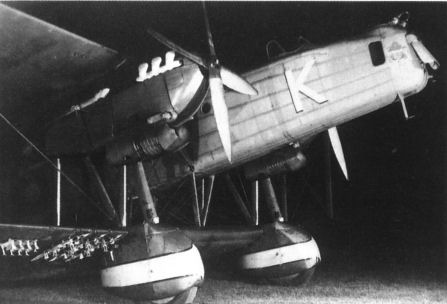
Air Enthusiast 2003-03 / B.Dunn - Half-way house
Night view of a Mk.II. Outboard of the wheel spats it carries racks for 112lb bombs and Light Series racks.
-

Aeroplane Monthly 1995-12 / P.Jarrett - Handley Page Heyford /By day and by night/
AC1/Arm Freddie Prince works on the underwing Universal carrier of a 97 Sqn Heyford at Aldergrove. Note the Light Series carrier outboard.
-

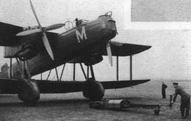
Flight 1935-09 / Flight
The Shelvoke & Drewry engine-driven tail-wheel trolley, for moving machines about on the ground.
-

Air-Britain Aeromilitaria 1994-01 / Handley Page Heyford
P of No. 102 Squadron (serial not known) at Armament Training Camp, Leuchars
-
Air-Britain Aeromilitaria 1994-01 / Handley Page Heyford
Регистрационный номер: K4877 K4877, H of 149 Squadron, visiting Brooklands
-

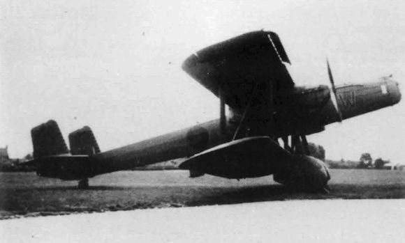
Air-Britain Aeromilitaria 1994-01 / Handley Page Heyford
K3781 (???), W of No. 99 Squadron
-

Aeroplane Monthly 1986-07 / Personal album
Регистрационный номер: K5187 An unusual visitor to Gravesend was Handley Page Heyford III K5187, which flew with 102 and 149 Sqns and was struck off RAF charge in 1940.
-

Aeroplane Monthly 1988-09 / P.Cooksley - RAF Kenley. Bulwark of London (1)
Регистрационный номер: K4867 An unusual visitor to RAF Kenley in 1938 was Heyford II K4867 of 149 Sqn. The letter “D” in dull red indicated A Flight.
-
Air-Britain Aeromilitaria 1994-01 / Handley Page Heyford
Регистрационный номер: K4026 K4026, N of No. 166 Squadron
-

Air-Britain Aeromilitaria 1994-01 / Handley Page Heyford
Регистрационный номер: K4037 K4037, G of No. 10 Squadron
-
Air-Britain Aeromilitaria 1994-01 / Handley Page Heyford
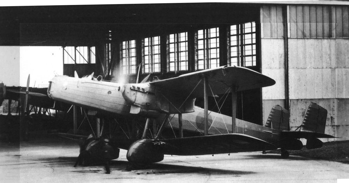
Регистрационный номер: K6868, K6869 Mk.III K6868 joined 9 Squadron in February 1936. In March 1939 it moved to 4 AOS and was struck off charge in July 1940.
K6869 of No. 9 Squadron running-up in front of a new hangar at Scampton -

Air Enthusiast 2003-03 / B.Dunn - Half-way house
With a 'C' Type hangar under construction in the background, another view from the press demonstration, believed to be at Scampton.
-
Air-Britain Aeromilitaria 1994-01 / Handley Page Heyford
Регистрационный номер: K4878 K4878, K of No. 7 Squadron at Finningley
-

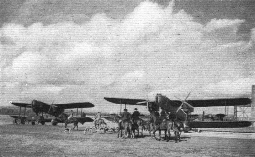
Flight 1936-10 / Flight
AFTER THE HARE: Apart from its touch of the picturesque, this photograph of local harriers meeting at Aldergrove R.A.F. station is interesting as showing machines of No. 502 (Ulster) (Bomber) Squadron and also in recalling the links between hunting and aviation, as expressed by such names as Handley Page Hare (which appeared just before the Heyford), Fairey Fox, Hawker Harrier, De Havilland Hound, Blackburn Beagle and Vickers Vixen.
-

Flight 1935-09 / Flight
Some of the Handley Page Heyfords (Rolls-Royce Kestrels) of No 10 (Bomber) Squadron.
-

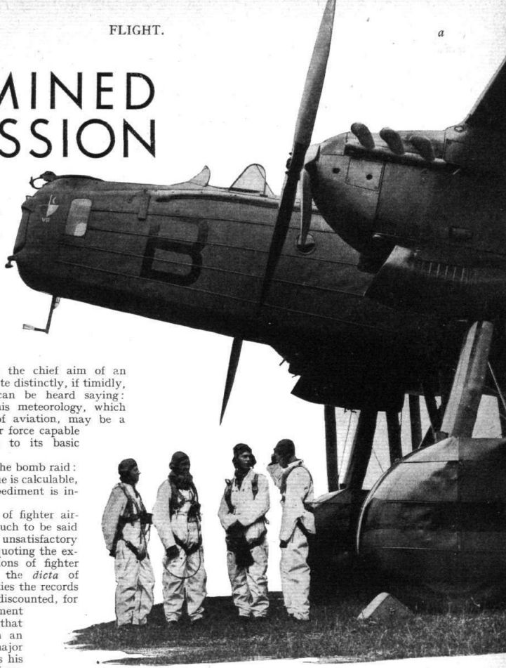
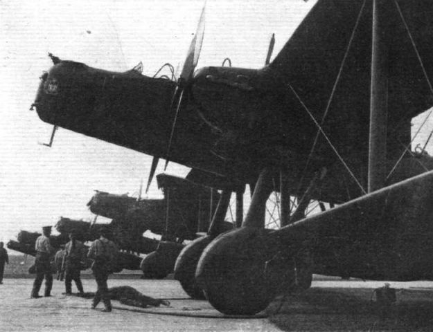
Flight 1937-10 / Flight
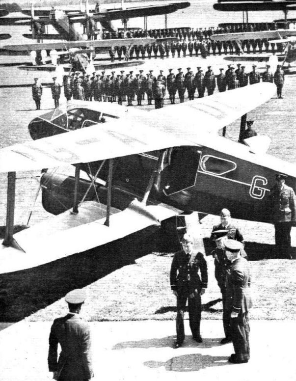
Not-so-new equipment: the visitors pass between the ranks of trusty Heyfords, each machine with its crew, in full flying kit, standing to attention.
-
Air-Britain Aeromilitaria 1994-01 / Handley Page Heyford
Регистрационный номер: K6889 [2] A pair of Heyford IIIs serving with No 166 Sqn before the war; nearest the camera is K6889 ‘R’ which went on to fly with No 4 Air Observers School until mid-1940.
-

Flight 1936-05 / Flight
A Heyford taxies out at Hornchurch for its "show."
-

Aeroplane Monthly 1995-12 / P.Jarrett - Handley Page Heyford /By day and by night/
Engine servicing was facilitated by specially designed ladders carried aboard the aircraft, and by the cowling side panels, which opened downwards to serve as work platforms.
-

Aeroplane Monthly 1984-09 / A.Lumsden, T.Heffernan - Probe Probare (6)
Access to the Rolls-Royce Kestrel engines was easy. The sides of the engine housing folded down enabling the engineers to stand while working on the engines.
-
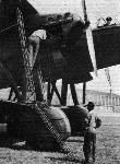
Flight 1936-03 / Flight
Attention to an engine. The ladders are very light and handy, and are carried on board.
The "kidney" or "ramshorn" type of exhaust system, which gives a noise reduction equal to that obtained with the more usual perforated tail pipes, is standard equipment on certain R.A.F. machines, notably the Handley Page Heyford. -

Aeroplane Monthly 1984-09 / A.Lumsden, T.Heffernan - Probe Probare (6)
Winding the elastic. The starting equipment of the Heyford was removable. On top of each wheel are supports for the shafts of the hand turning gear.
-

Flight 1930-07 / Flight
Prince George is shown the new night bomber with its streamlined wheels.
-

Aeroplane Monthly 1995-12 / P.Jarrett - Handley Page Heyford /By day and by night/
A crew member of 97 Sqn uses the footholes in the lower mainplane to approach the underfuselage entry hatch. The spring-loaded cover of the lower hole has yet to close.
-

Flight 1936-07 / Flight
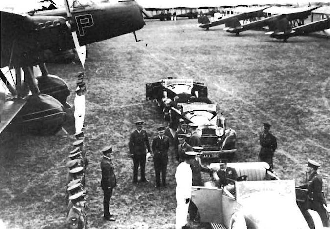
The scene at Mildenhall on the arrival of the King, with a background of Hinds and Heyfords.
Другие самолёты на фотографии: De Havilland Dragon Rapide / Dominie / D.H.89 - Великобритания - 1934Hawker Hind - Великобритания - 1934
-

Aeroplane Monthly 1994-12 / G.Wansbrough-White - What's in a name? (2)
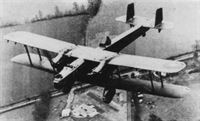
THE STAGE SET: This aerial photograph of the Royal Air Force Display machines assembled in the operational park at Hendon forms a fitting introduction to the pictures, in the ensuing pages, of the Display in progress. There are eight monoplanes in the assembly - Ansons (third row) and Clouds (fifth).
Line-up of about 130 1936 RAF Display participants - all biplanes except for the Ansons and Saro Cloud amphibians.
The stage is set for the 1936 RAF Display at Hendon. The monoplanes (Ansons and Saro Clouds) are totally outnumbered by the biplanes including Heyfords, Bulldogs, Gauntlets, Fairey IIIFs, Harts, Hinds, Tiger Moth, Overstrands etc, etc. This entire area has since disappeared beneath a sea of bricks and concrete.Другие самолёты на фотографии: Avro Anson / Type 652 - Великобритания - 1935Boulton Paul Overstrand / P.75 - Великобритания - 1933Bristol Bulldog - Великобритания - 1927De Havilland Tiger Moth / D.H.82 - Великобритания - 1931Fairey Fairey IIIF - Великобритания - 1926Gloster Gauntlet - Великобритания - 1929Hawker Hart - Великобритания - 1928Hawker Hind - Великобритания - 1934Saunders-Roe Cloud / A.19 - Великобритания - 1930
-

Flight 1937-07 / Flight
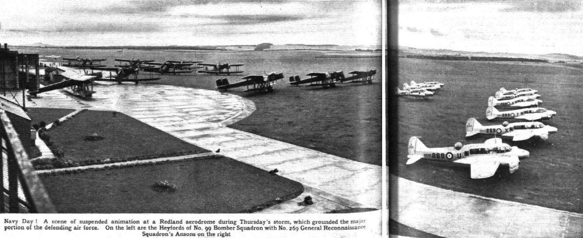
Navy Day! A scene of suspended animation at a Redland aerodrome during Thursday's storm, which grounded the major portion of the defending air force. On the left are the Heyfords of No. 99 Bomber Squadron with No. 269 General Reconnaissance Squadron's Ansons on the right
Другие самолёты на фотографии: Avro Anson / Type 652 - Великобритания - 1935
-

Flight 1935-07 / Flight
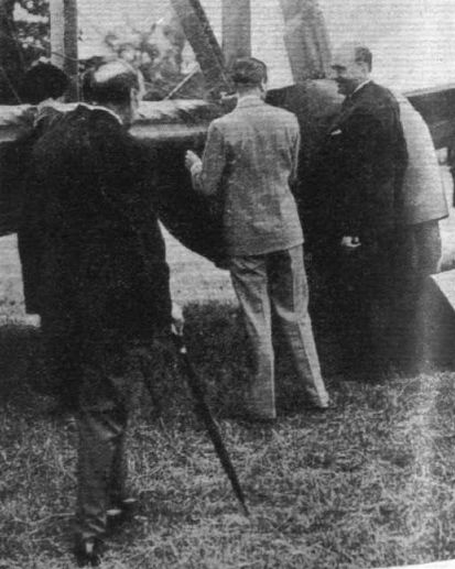
The King at Mildenhall with the Prince of Wales and the Duke of York. He has stopped to inspect the "Heyfords" of No. 99 (B) Squadron.
-

Air Pictorial 1977-07 / M.Bowyer - R.A.F. on Parade - the 1935 Jubilee Review
Three Kings pause before a Handley Page Heyford of No. 99 Squadron. King George V is seated in the Rolls-Royce, behind which are the Prince of Wales (who became King Edward VIII) and the Duke of York (later King George VI)
-

-

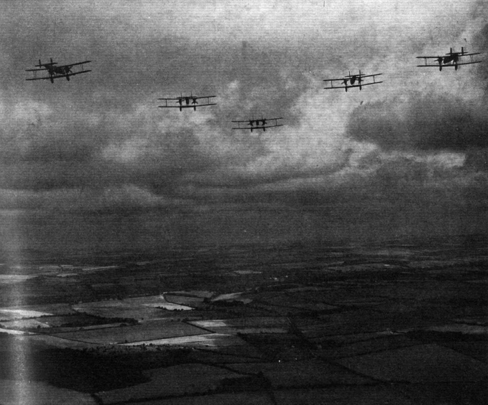
Flight 1935-07 / Flight
The Heavy Bomber Wing, consisting of No. 99 (Bomber) Squadron (above) and No. 10 (Bomber) Squadron (below) flying their "Heyfords" past the King at Duxford. Each squadron is in the formation "flights astern."
-
Air Pictorial 1977-07 / M.Bowyer - R.A.F. on Parade - the 1935 Jubilee Review
The twenty Heyfords of Nos. 99 and 10 Squadrons set off to lead the fly-past
-

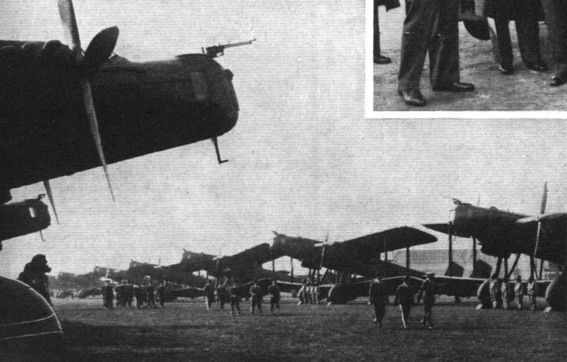
Flight 1933-07 / Flight
ONLY A "SPARTAN" WOULD ATTACK THE "HEYFORD": With a gunner above and a gunner below, in a rotatable turret, the new Handley Page night bomber is well defended. On this occasion the "Heyford" was piloted by Sqd. Ldr. T. England and the "Spartan" by Capt. Cordes.
Другие самолёты на фотографии: Simmonds Spartan - Великобритания - 1928
-
Flight 1933-07 / Flight
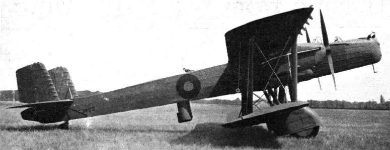
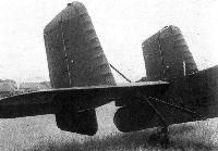
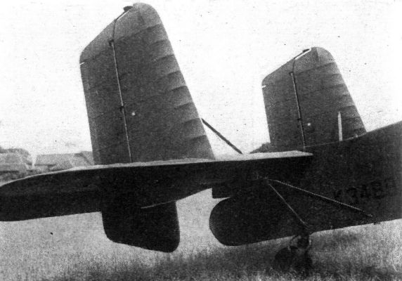
TWIN RUDDERS AND MONOPLANE TAIL: The aerodynamic horn balances of the rudders are below the tailplane, while the mass balances are at the top.
-

Aeroplane Monthly 1995-12 / P.Jarrett - Handley Page Heyford /By day and by night/
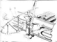
THE HINGED STERN CAP: This gives access to the tailwheel support, tailplane trimming gear, etc. Since this photograph was taken mass balances have been fitted the elevators, and are housed inside the fuselage.
The hinged aluminium rear-fuselage fairing folded back to reveal the variable-incidence gear for the tailplane and the tailwheel installation. -

Flight 1933-07 / Flight
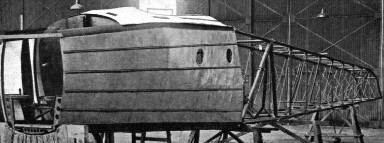
THE FUSELAGE: The front portion is a metal monocoque structure, while the rear is a steel tube wire-braced girder.


-

Aeroplane Monthly 1995-12 / P.Jarrett - Handley Page Heyford /By day and by night/
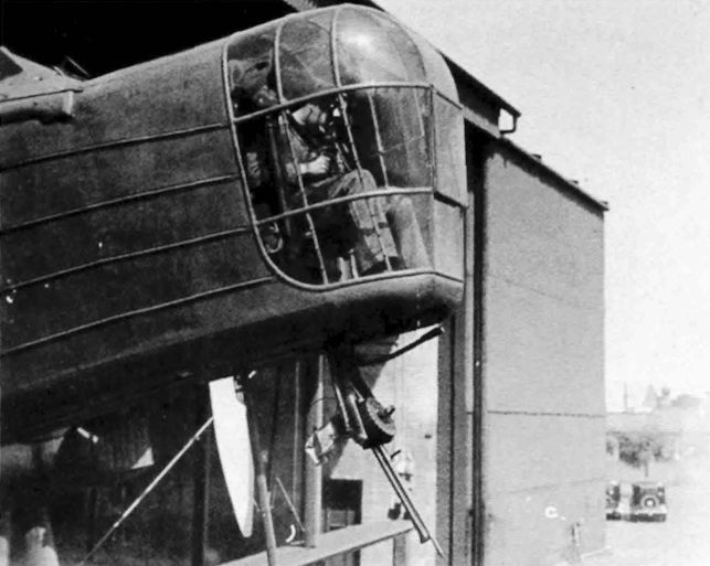
Регистрационный номер: K3500 [7] Looking back at the pilot from the nose gunner’s position. Note the guard on the cockpit side to prevent the occupants inadvertently touching the revolving propeller.
Forward gunner’s view of the pilot, in this case flying Heyford K3500 from Radlett in March 1934. -

Aeroplane Monthly 1995-12 / P.Jarrett - Handley Page Heyford /By day and by night/
Регистрационный номер: J9130 [14] The cockpit of the prototype Heyford, J9130, photographed in May 1931. The second pilot's controls could be detached in a moment when not required, as they are in this picture. The bulkhead door dividing the pilot's cockpit from the forward gunner is open.
A Heyford cockpit, with the engine control quadrant to the pilot’s right, and the bomb-aimer’s position in the nose visible. -

Aeroplane Monthly 1984-09 / A.Lumsden, T.Heffernan - Probe Probare (6)
Регистрационный номер: J9130 [14] Another view of the Heyford prototype's cockpit showing this time the copilot's controls in position and the twofold bulkhead door to the forward gunner's position closed. The large trim wheel is seen left of centre of the picture. Note too the folding seats; the higher one is in fact the backrest.
-
Flight 1933-07 / Flight
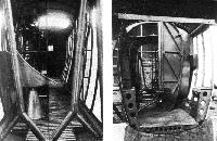
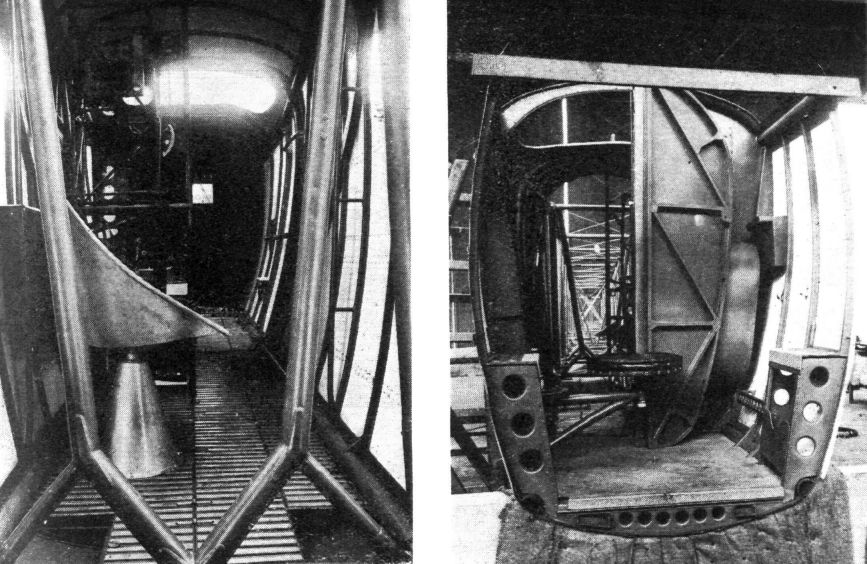
INTERIOR VIEWS: These were taken before the machine was finished. On the left, the wireless compartment, looking forward. On the right, a view into the front gunner's compartment, taken before the nose cap was put on. Note the firing steps and the "piano stool" seat.
-

Aeroplane Monthly 1995-12 / P.Jarrett - Handley Page Heyford /By day and by night/
The nose gunner of a 97 Sqn Heyford fires on surface targets in Lough Neagh, Northern Ireland, during Armament Practice Camp at Aldergrove in 1938.
-

Air-Britain Aeromilitaria 1997-01 / Out of the Archives
Регистрационный номер: K3489 [10] Helmut Stieger is best-known for his development of the Monospar wing but among his other activities was an attempt to produce a turret for the noses of bombers.
The design was intended to give a wide field of fire while providing the gunner with protection from the wind. The first example was taken to Martlesham Heath for testing in the nose of Heyford K3489 in April 1936. The Aeroplane & Armament Experimental Establishment carried out trials in June 1936 over the Orfordness ranges and issued a report (M/Arm/463/1).
The gun was carried externally on a cradle below the turret and when not in use could be stowed close to the fuselage but could be lowered for firing by a lever in the turret. It was fitted with a small wind-vane to assist in balancing and could move around to face in any direction. -

Aeroplane Monthly 1995-12 / P.Jarrett - Handley Page Heyford /By day and by night/
The gunner is barely visible in this view of the “dustbin" of a 97 Sqn Heyford, but his Lewis gun with its Norman vane sight and the canvas pockets for his toes are well show.
-

Aeroplane Monthly 1984-09 / A.Lumsden, T.Heffernan - Probe Probare (6)
Регистрационный номер: K3489 [10] Close-up view of the retractable pillar box-type gun turret aft of the wings on Heyford K3489 at Radlett in June 1933.
-
Flight 1933-07 / Flight
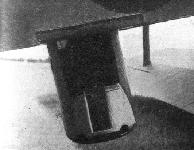
Регистрационный номер: K3489 [10] THE PILLAR BOX: This is raised, lowered and rotated by the gunner himself.


-

Aeroplane Monthly 1995-12 / P.Jarrett - Handley Page Heyford /By day and by night/
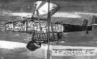
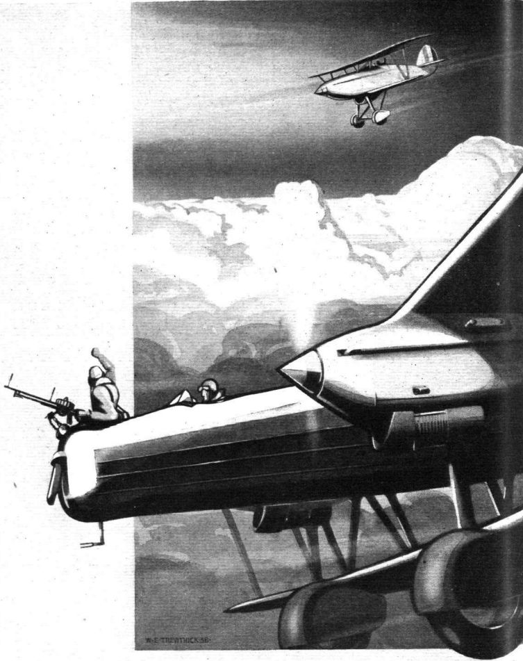
Регистрационный номер: K3498 KEITH WOODCOCK'S painting depicts Heyford K3498 “Q” of 99 Sqn preparing for night flying.
-
-

-

-

-

Aeroplane Monthly 1988-12 / P.Masefield - Wren
One of Wren's early illustrations appeared in the January 1933 issue of W. E. Johns’ Popular Flying magazine. Though he had already developed a style as a caricaturist, there is no evidence of it in this artwork.
Другие самолёты на фотографии: Farman HF.24 - Франция - 1913
-

Aeroplane Monthly 1988-04 / 70 years fly by! Royal Air Force 1918 to 1988
Другие самолёты на фотографии: Handley Page Harrow / H.P.54 - Великобритания - 1936
-
-

-
Flight 1933-07 / Flight
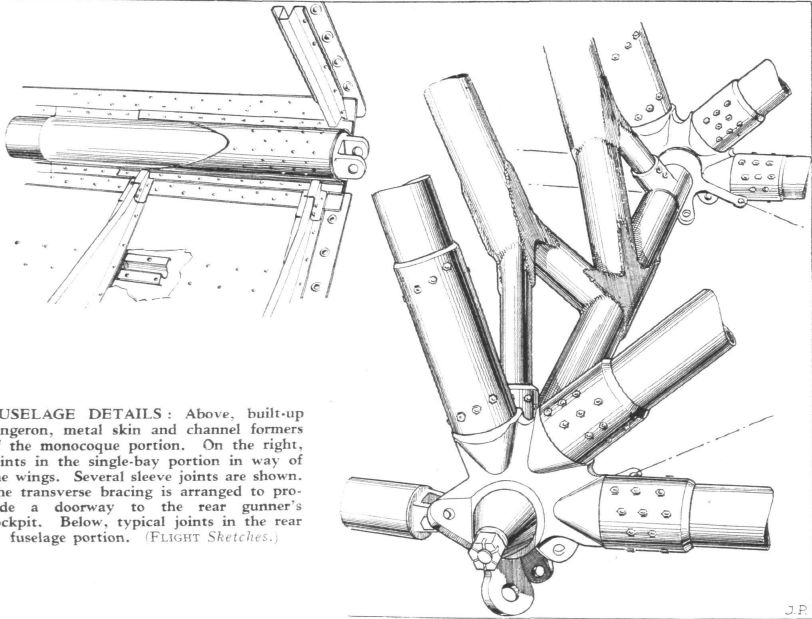
FUSELAGE DETAILS: Left, built-up longeron, metal skin and channel formers of the monocoque portion. On the right, joints in the single-bay portion in way of the wings. Several sleeve joints are shown. The transverse bracing is arranged to provide a doorway to the rear gunner's cockpit.
-
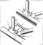
Flight 1933-07 / Flight
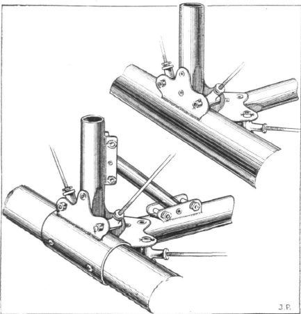
FUSELAGE DETAILS: Typical joints in the rear fuselage portion.
-
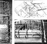
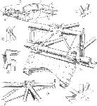
Flight 1933-07 / Flight
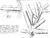
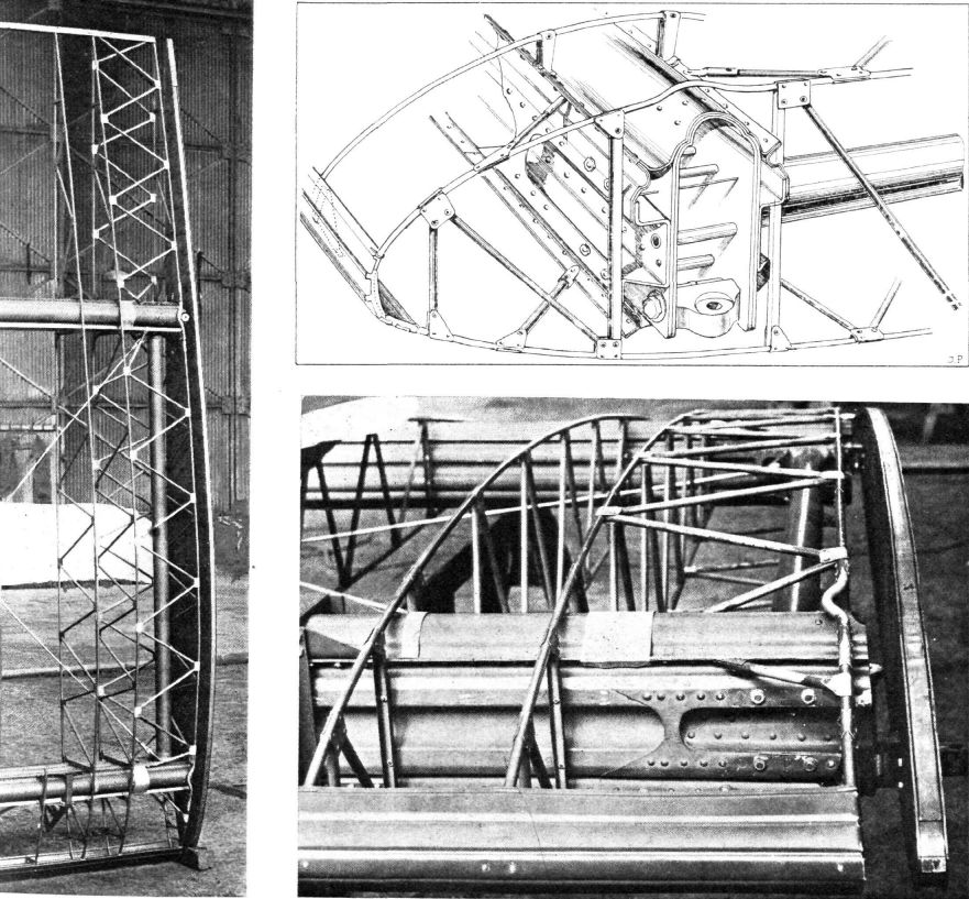
WING CONSTRUCTION: The two photographs show the general wing construction, while the sketch illustrates some of the details thereof. They relate to a starboard lower plane.
-
Flight 1933-07 / Flight
Details of an outer lower wing, with interplane strut fitting, and support for lifting jack. The internal drag bracing strut is of the same section as that of the main spars, but of slightly smaller dimensions.
-
Flight 1933-07 / Flight
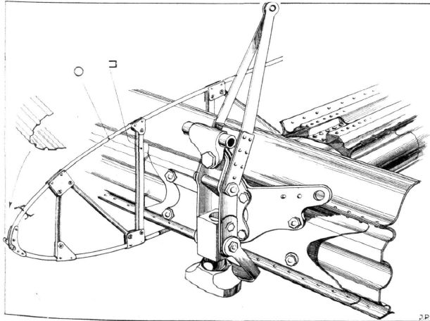
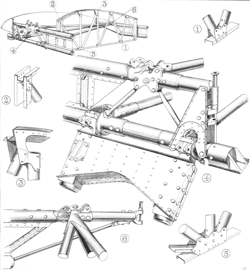
LOWER CENTRE SECTION: The construction of this differs from that employed generally in the wings. The small sketch in the upper left-hand corner shows the location of the various numbered details.
-
-

Air Enthusiast 2003-03 / B.Dunn - Half-way house
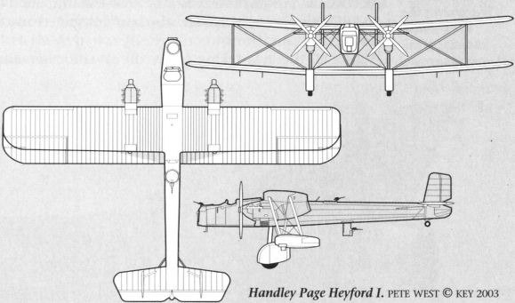
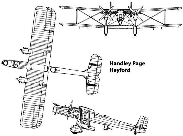
Handley Page Heyford.
-

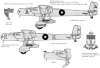
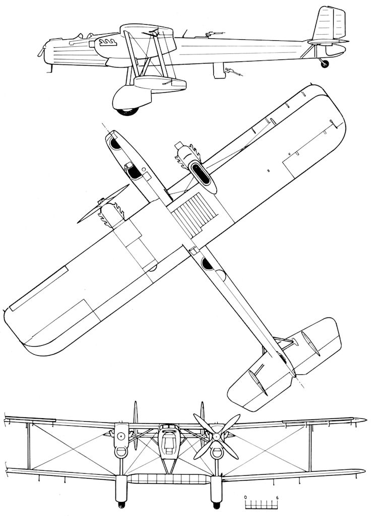
Мировая Авиация 149
Handley Page Heyford
-
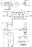
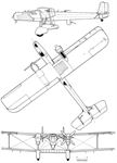
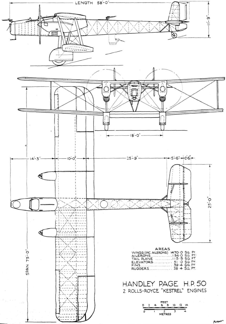
Flight 1933-07 / Flight
Handley Page H.P.50 2 Rolls-Royce "Kestrel" Engines
-


Тип фотографий
- Все фото (126)
- Ч/б фото (98)
- Кабина (9)
- Рисунки, схемы, чертежи (19)