

Jane's Encyclopedia of Aviation
Whitworth A.W.15 Atalanta (UK)
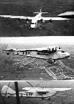
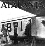
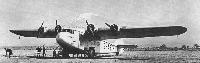
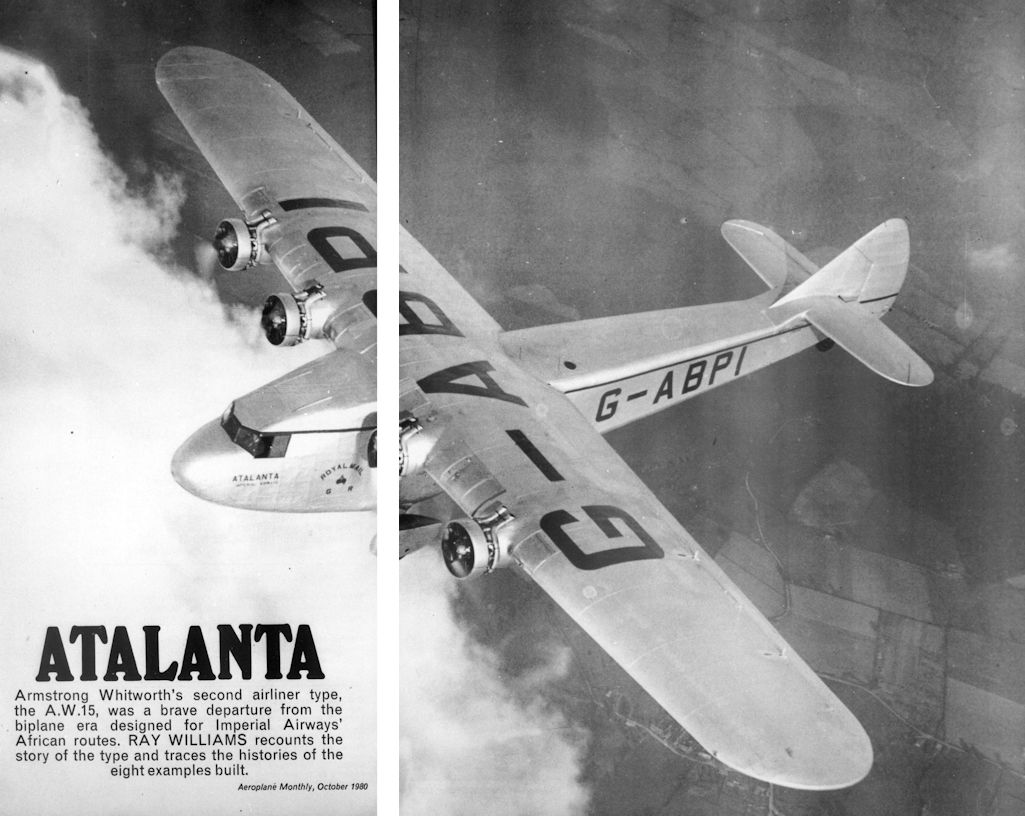
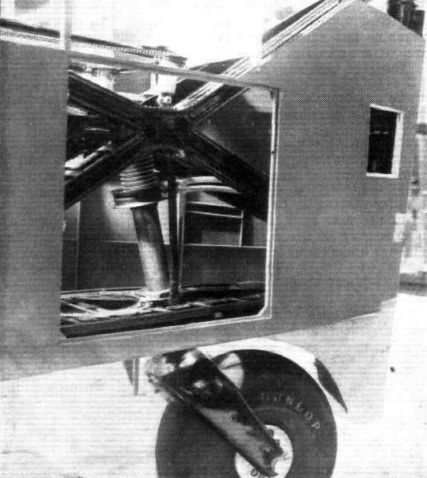
In 1930 Imperial Airways drew up a specification for a new four-engined airliner to serve in Africa between Kisumu, western Kenya, and Cape Town, South Africa. As a complete breakaway from the more traditional biplane airliner and in order to meet the rather exacting performance figures demanded, Armstrong Whitworth designed the A.W.15: a high-wing cantilever monoplane with four engines mounted in the leading edges of the wings, an ingenious short special low drag landing gear in which the oleo legs and A.W.52. radius rods and most of the axles were within the fuselage, and fully enclosed accommodation for the crew of three and passengers. Passenger accommodation varied between nine (plus mail and/or freight carried around and beneath the corridor) for the African route and up to 17 for European services. A toilet was provided at the back of the cabin. Named Atalanta, the first A.W.15 flew on 6 June 1932.
On 26 September 1932 Atalanta flew the route to Brussels and Cologne and thereafter other A.W.15s linked London, Paris and Zurich. In 1933 four A.W.15s operated the Kisumu-Cape Town route; in the same year Indian Transcontinental Airways took over the operation of two of the A.W. 15s under an agreement with Imperial Airways for a shared service in India. In the following year A.W.15s were used by Imperial Airways on the shared service to Australia, operated with Qantas. In all eight A.W.15s were built. The name Atalanta was given to the first aircraft and subsequently the fourth, following an accident to the first, which then took on the name Arethusa. The other six were named Amalthea, Andromeda, Artemis, Athena, Astraea and Aurora. In 1940 the remaining five A.W.15s were taken over by BOAC, but were handed over to the Indian Air Force the following year.
Data: Engines four 253.3 (340 hp) Armstrong Siddeley Serval III radials Wing span 27.43 m (90 ft 0 in) Length 21.79 m (71 ft 6 in) Max T-O weight 9,526 kg (21,000 lb) Max level speed 251 km/h (156 mph) Range 1,030 km (640 miles)
Описание:
- Jane's Encyclopedia of Aviation
- Flight, July 1932
The A.W. XV Monoplane - Flight, November 1932
British Aircraft
Фотографии

-

Aeroplane Monthly 1980-11 / R.Williams - Atalanta (2)
Регистрационный номер: G-ABTM [12], DG454 [12], VT-AEG [12] G-ABTM of Imperial Airways
-

Aeroplane Monthly 1980-11 / R.Williams - Atalanta (2)
Регистрационный номер: VT-AEG [12], DG454 [12], G-ABTM [12] VT-AEG of Indian Transcontinental Airways
-

Aeroplane Monthly 1980-11 / R.Williams - Atalanta (2)
Регистрационный номер: DG454 [12], G-ABTM [12], VT-AEG [12] DG454 of the Indian Air Force
-
Aeroplane Monthly 1980-10 / R.Williams - Atalanta (1)
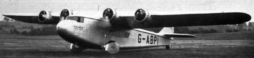
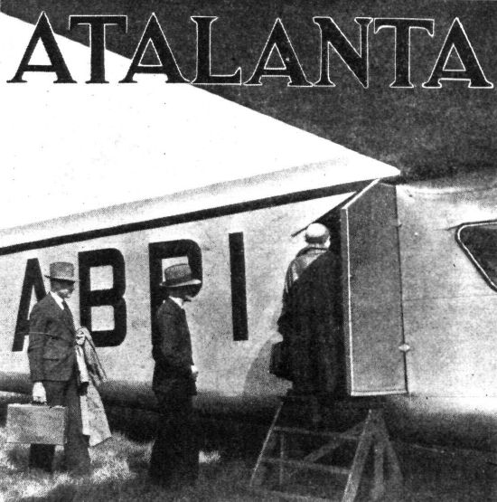
Регистрационный номер: G-ABPI [29], VT-AEF [29] The prototype A.W.15 Atalanta shortly after it was completed. Note the absence of the name on the nose.
-

Flight 1932-07 / Flight
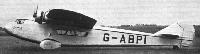
Регистрационный номер: G-ABPI [29], VT-AEF [29] RUNNING UP: Mr. Campbell-Orde testing his "Double Mongoose" engines before making a flight at Whitley.
-
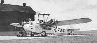
Flight 1932-07 / Flight
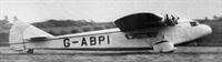
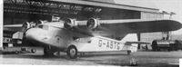
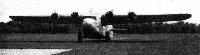
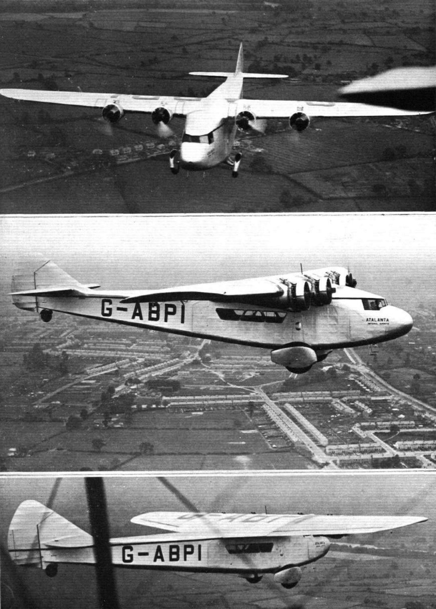
Регистрационный номер: G-ABPI [29], VT-AEF [29] SIDE VIEW OF THE "ATALANTA": Note the "spats" over the wheels, and the low ground clearance.
-

Aeroplane Monthly 1980-10 / R.Williams - Atalanta (1)
Регистрационный номер: G-ABPI [29], VT-AEF [29] -
Air Enthusiast 1997-05 / R.Bonser, K.Ellis - Cuckoo in the Nest
Регистрационный номер: G-ABPI [29], VT-AEF [29] As witness the comparison table, while the AW.15 Atalanta shared a similar format with its successor, it was a substantially smaller airframe.
-

Aeroplane Monthly 1980-10 / R.Williams - Atalanta (1)
Регистрационный номер: G-ABPI [29], VT-AEF [29] The prototype Armstrong Whitworth Atalanta photographed in September 1932. G-ABPI was the only Atalanta equipped with fully-faired wheel spats.
-

Aeroplane Monthly 1974-03 / P.Moss - Wings for the Empire (3)
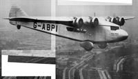
Регистрационный номер: G-ABPI [29], VT-AEF [29] The first Armstrong Whitworth A.W. 15 for Imperial Airways, G-ABPI Atalanta, which flew on the Brussels-Cologne service on September 26, 1932.
-
Flight 1932-07 / Flight
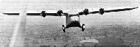
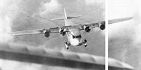
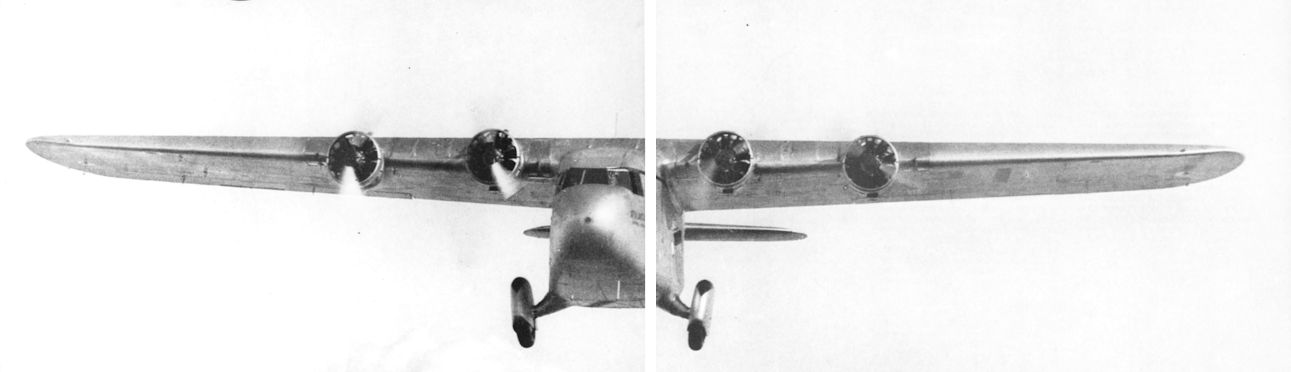
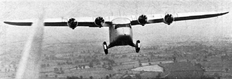
Регистрационный номер: G-ABPI [29], VT-AEF [29] THE A.W. XV IN THE AIR: This front view indicates the very low frontal area of the machine.
-
Aeroplane Monthly 1980-10 / R.Williams - Atalanta (1)
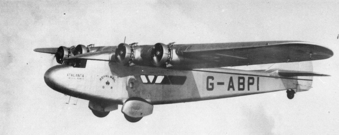
Регистрационный номер: G-ABPI [29], VT-AEF [29] The prototype A.W.15 Atalanta during a press demonstration in September 1932.
-
Flight 1932-07 / Flight
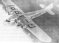
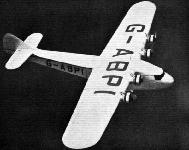
Регистрационный номер: G-ABPI [29], VT-AEF [29] THE "ATALANTA" IN FLIGHT: This view from above gives a good idea of the plan form, and also shows the neat merging of the engine housings into the wing surface.
-
Aeroplane Monthly 1980-11 / R.Williams - Atalanta (2)
Регистрационный номер: G-ABPI [29], VT-AEF [29] The prototype A.W.15 Atalanta, G-ABPI, during an early test flight in September 1932.
-
Flight 1935-05 / Flight
Регистрационный номер: G-ABPI [29], VT-AEF [29] 6 июня 1932г.: поднялся в воздух A.W.XV Atalanta, созданный для "Imperial Airways" и перевозивший почту и пассажиров в Южной Африке и на Индостане.
The first Armstrong Whitworth A.W.XV on a test flight in its original form with spatted mainwheels. -
Flight 1932-07 / Flight
Регистрационный номер: G-ABPI [29], VT-AEF [29] FOR THE AFRICAN AIR ROUTE: The Armstrong Whitworth "Atalanta" (four Armstrong-Siddeley "Double Mongoose") is the first of eight machines being built for Imperial Airways, Ltd. The extremely careful streamlining should be noted.
-
Flight 1933-10 / Flight Advertisements
Регистрационный номер: G-ABPI [29], VT-AEF [29] -

Flight 1932-07 / Flight
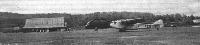
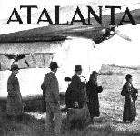
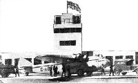
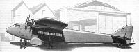
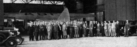
Регистрационный номер: G-ABPI [29], VT-AEF [29] Members of the Chartered Surveyors Institution at the Armstrong-Whitworth Aircraft Factory at Coventry. The aircraft in the hangar is the new AW.XV "Atalanta" built for the Imperial Airways' African route.
-
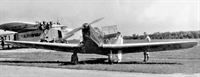
Aeroplane Monthly 1980-11 / R.Williams - Atalanta (2)
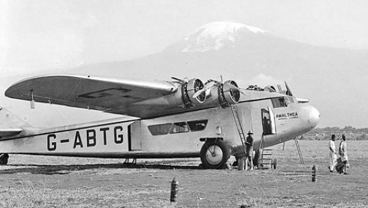
Регистрационный номер: G-ABTG [2] Imperial Airways' Atalanta G-ABTG Amalthea, seen at Croydon, with three engines running. Note the H.P.W10 G-EBMM in the hangar. Amalthea was later to crash at Kisumu, Kenya, in July 1938.
Другие самолёты на фотографии: Handley Page H.P.18 (W.8) / H.P.30 (W.10) - Великобритания - 1919
-

Авиация и Космонавтика 2018-09 / В.Морозов - В желтой, жаркой Африке: Авиация Родезии и Зимбабве (1)
Регистрационный номер: G-ABTG [2] Четырехмоторный Армстронг-Уитворт AW.15 «Атланта» авиакомпании «Imperial Airways», использовавшийся на британских авиалиниях юга Африки с 1933 г.
-

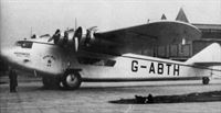
Aeroplane Monthly 1985-09 / Personal album
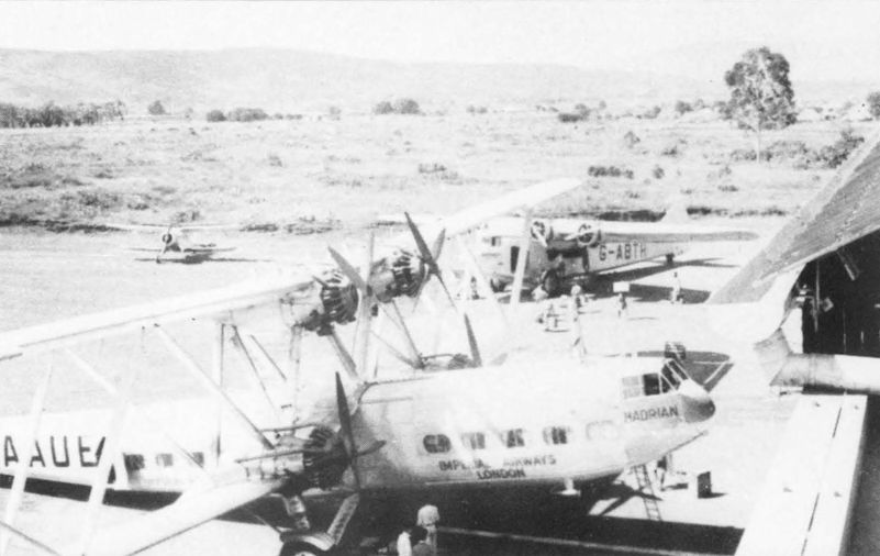
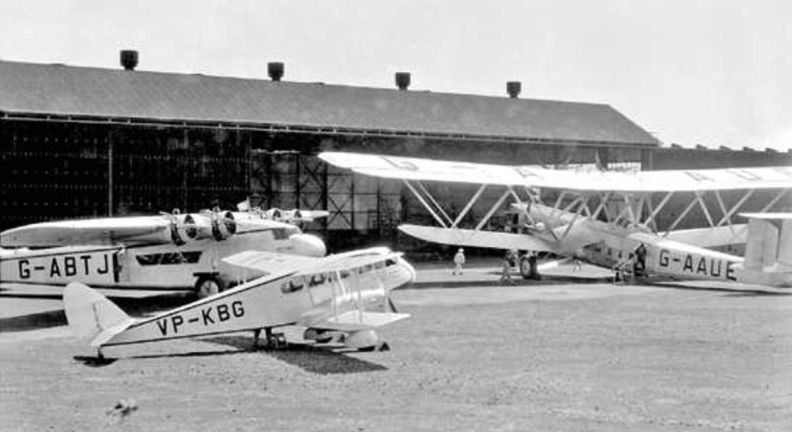
Регистрационный номер: G-ABTH [4] Handley Page H.P.42E G-AAUE Hadrian with Armstrong Whitworth Atalanta G-ABTH Andromeda at an unknown African aerodrome in the mid-Thirties. This Atalanta was originally put on the Cape Town - Kisumu route in February 1933. The aircraft was eventually withdrawn from Imperial Airways service at Alexandria after suffering mainspar damage.
Другие самолёты на фотографии: Handley Page H.P.42 / H.P.45 - Великобритания - 1930
-
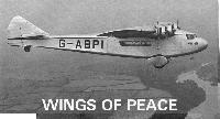
Aeroplane Monthly 1986-06 / J.Stroud - Wings of Peace
Регистрационный номер: G-ABTH [4] Atalanta G-ABTH Andromeda at Moshi.
-
Aeroplane Monthly 1980-11 / R.Williams - Atalanta (2)
Регистрационный номер: G-ABTH [4] Atalanta G-ABTH Andromeda, was put into service on the Cape Town-Kisumu route during early 1935 and was eventually withdrawn from flying in June 1939.
-
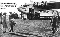
Flight 1935-02 / Flight Advertisements
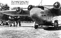
Регистрационный номер: G-ABTH [4] The Imperial Airway's Liner Andromeda of the Atalanta class at Nairobi.
-

Aeroplane Monthly 1980-11 / R.Williams - Atalanta (2)
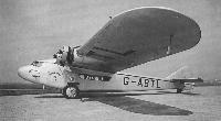
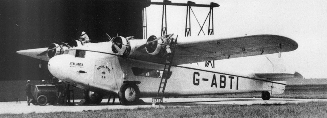
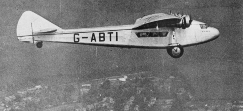
Регистрационный номер: G-ABTI [7] Atalanta G-ABTI was surreptitiously named Atalanta when the prototype was damaged in a forced landing.
-
Aeroplane Monthly 1986-06 / J.Stroud - Wings of Peace
Регистрационный номер: G-ABTI [7] G-ABTI Atalanta at Broken Hill on the South Africa route.
-
Aviation Historian 24 / R.Pegram - Imperial Airways. The 1930s: a cause for concern?
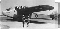
Регистрационный номер: G-ABTI [7] The fourth Armstrong Whitworth AW.XV Atalanta, G-ABTI, during a stop on its Nairobi-Cape Town route for Imperial in 1933. That year the type also began services on the Karachi-Singapore sector of the joint Imperial/Qantas route connecting the UK and Australia. In total eight Atalantas were built.
-

Aeroplane Monthly 1974-03 / P.Moss - Wings for the Empire (3)
Регистрационный номер: G-ABTI [7] A.W.15, G-ABTI, the second to bear the name Atalanta.
-
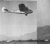
Aeroplane Monthly 1980-10 / R.Williams - Atalanta (1)
Регистрационный номер: G-ABTI [7] "ATALANTA" IN AFRICA: Imperial Airways' Atalanta leaving Capetown with passengers and mails for England. Note Table Mountain in the background.
Atalanta G-ABTI which replaced G-ABPI and was also named Atalanta, leaving Cape Town for London on April 26, 1934. -
Aviation Historian 23 / E.Martyn - Flying home for the sheep-shearing
Регистрационный номер: G-ABTI [7] The Gull attracts official interest during Clark’s stopover at Darwin. Note the Imperial Airways (IA) Armstrong Whitworth Atalanta, G-ABTI, which may have pushed on from its usual Karachi-Singapore service owing to a problem on the Qantas section of the joint lA/Qantas UK-Australia route.
Другие самолёты на фотографии: Percival Gull - Великобритания - 1932
-
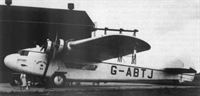
Aeroplane Monthly 1980-11 / R.Williams - Atalanta (2)
Регистрационный номер: G-ABTJ [4] Atalanta G-ABTJ, Artemis, in one piece
-
Авиация и Космонавтика 2018-09 / В.Морозов - В желтой, жаркой Африке: Авиация Родезии и Зимбабве (1)
Регистрационный номер: G-ABTJ [4] Основа британской пассажирской авиации в африканских колониях - DH.89 «Драгон Рапид» (на переднем плане) и Армстронг-Уитворт AW.15 «Атланта» (за ним). Фото сделано в Палестине в 1937 г.
Другие самолёты на фотографии: De Havilland Dragon Rapide / Dominie / D.H.89 - Великобритания - 1934
-

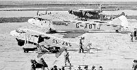
Aviation Historian 36 / R.Pegram - The golden age?
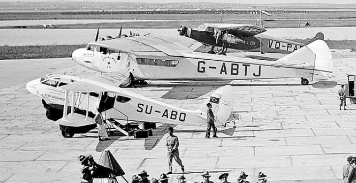
Регистрационный номер: G-ABTJ [4] A trio of typical aircraft operating commercial services in Africa in the 1930s, including two of IAL’s most important landplanes; Handley Page H.P.42E G-AAUE Hadrian (furthest right) and Armstrong Whitworth AW.15 Atalanta G-ABTJ Artemis, behind Wilson Airways’ de Havilland D.H.84 Dragon VP-KBG, at Kisumu in Kenya.
Другие самолёты на фотографии: De Havilland Dragon / D.H.84 - Великобритания - 1932Handley Page H.P.42 / H.P.45 - Великобритания - 1930
-

Aeroplane Monthly 1980-11 / R.Williams - Atalanta (2)
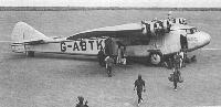
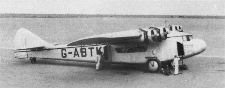
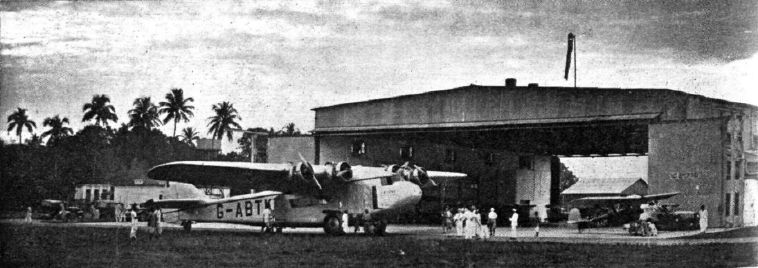
Регистрационный номер: G-ABTK [3] Atalanta G-ABTK Athena, later burnt out in a hangar fire at Willingdon Airport, Delhi.
-
Aeroplane Monthly 1986-06 / J.Stroud - Wings of Peace
Регистрационный номер: G-ABTK [3] G-ABTK Athena being loaded at Karachi.
-
Flight 1933-10 / Flight
Регистрационный номер: G-ABTK [3] EN ROUTE FOR RANGOON: The Athena, of Indian Trans-Continental Airways, about to leave Calcutta, under monsoon skies, for Rangoon with the first Croydon air mails.
-

Aeroplane Monthly 1974-03 / P.Moss - Wings for the Empire (3)
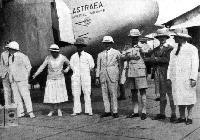
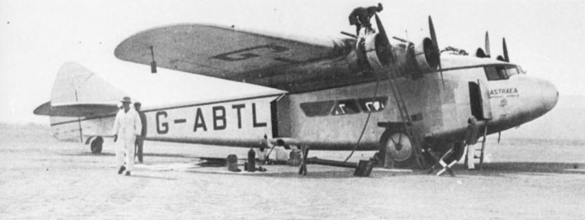
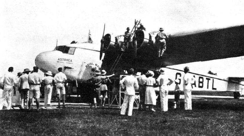
Регистрационный номер: G-ABTL [15] Atalanta, G-ABTL, Astraea, at Karachi. Astraea was impressed into Indian Air Force service in March 1940 at DG450.
-

Aeroplane Monthly 1985-09 / Personal album
Регистрационный номер: G-ABTL [15] Armstrong Whitworth Atalanta G-ABTL Astraea photographed during an unscheduled stop at Aboukir, presumably for refuelling. G-ABTL was later transferred to the Indian Air Force as DG450.
-
Aeroplane Monthly 1986-06 / J.Stroud - Wings of Peace
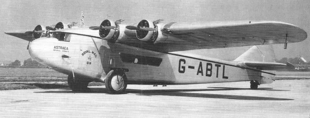
Регистрационный номер: G-ABTL [15] G-ABTL Astraea at Croydon before the Australia survey flight.
-

Air Enthusiast 2000-11 / G.Warner - Founding Fathers (2)
Регистрационный номер: G-ABTL [15] The AW Atlanta was "ugly but functional". Illustrated is G-ABTL ‘Astraea’.
-

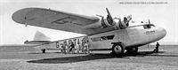
Flight 1933-08 / Flight Advertisements
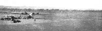
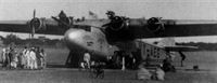
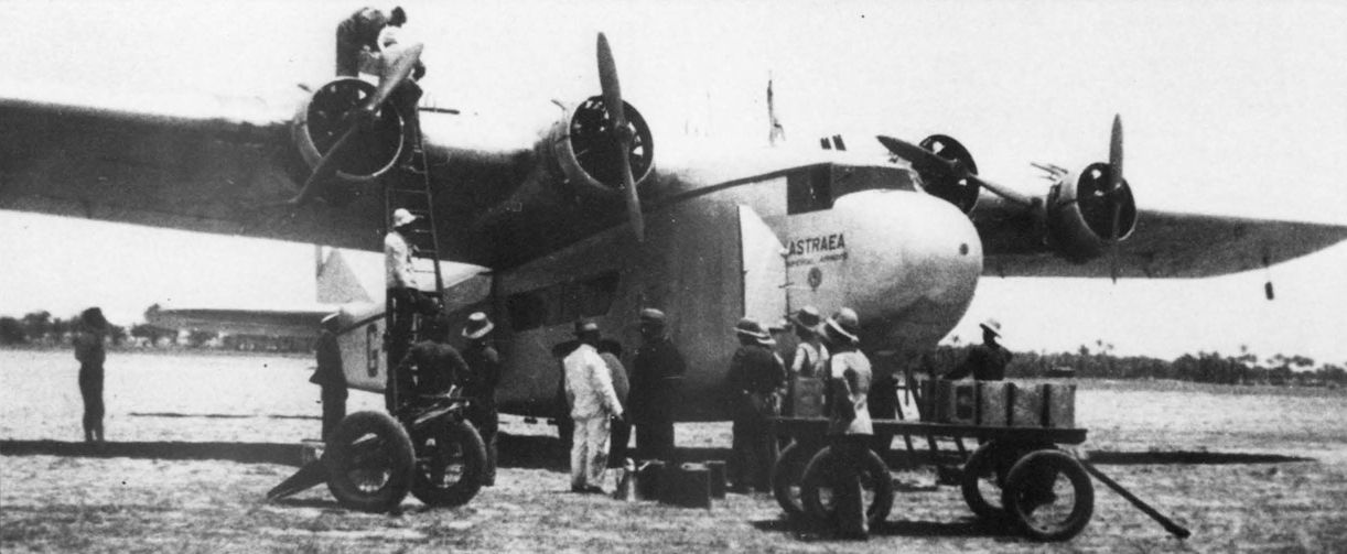
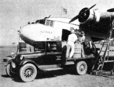
Регистрационный номер: G-ABTL [15] The Armstrong Whitworth Astraea (four Siddeley Serval engines) refuelling at Sourabaya.
-

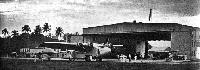
Flight 1935-03 / Flight Advertisements
Регистрационный номер: G-ABTL [15] The Astraea, an Imperial Airway's Liner of the Atalanta class, in front of the hangar at Dum-Dum, Calcutta Airport.
-

Flight 1933-11 / Flight
Регистрационный номер: G-ABTL [15] ON THE EDGE OF AUSTRALIA: The Astraea takes in a supply of "Shell" at Darwin before leaving for the Dutch East Indies.
-
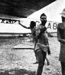
Flight 1933-11 / Flight
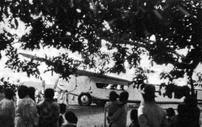
Регистрационный номер: G-ABTL [15] AN INCIDENT IN AUSTRALIA: The native "King" of Bathurst Island, highly impressed by the visit of Astraea - "the White King's Messenger" - gave the airliner a hearty welcome.
-

Flight 1933-11 / Flight
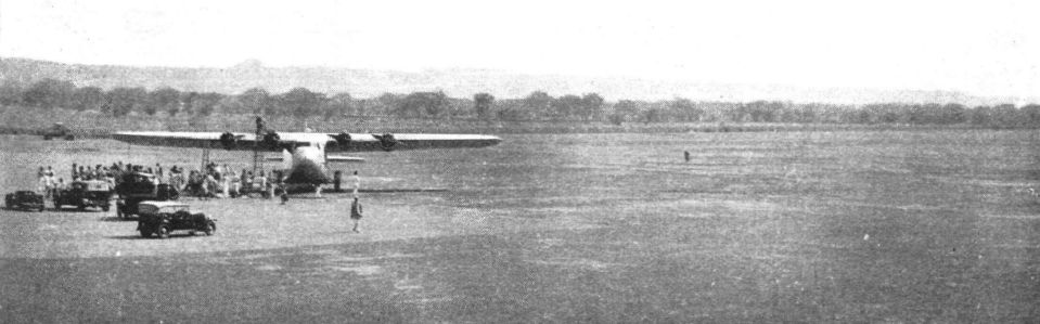
Регистрационный номер: G-ABTL [15] A REFUELLING HALT: Astraea made a brief halt on the pretty island settlement of Muntok (about 300 miles from Batavia) to pick up more "Shells."
-
Flight 1933-11 / Flight
Регистрационный номер: G-ABTL [15] -
Flight 1933-11 / Flight
Регистрационный номер: G-ABTL [15] IN INDIA: This view gives a good idea of the excellent aerodrome at Jodhpur, the last stage of the journey from Calcutta.
-

Aviation Historian 41 / D.Stringer - Around the world in 28 days!
Регистрационный номер: G-ABTL [15] Imperial Airways’ Armstrong Whitworth XV G-ABTL, named Astraea, was one of eight examples of the Atalanta-class operated by the airline from 1932. It is seen here over Penang in the Straits Settlements of British Malaya in September 1934. Our traveller would have joined up with the AW.XV at Penang, northbound from Singapore.
RIGHT A typically stylish Imperial Airways timetable detailing services to the Middle and Far East and on to Australia, dated September 1936. For the pioneering around-the-world flight proposed in 1937, Imperial would have taken responsibility for the sectors from Hong Kong westwards through French Indochina, Malaya, Siam, India, Iraq, Egypt and ending in Greece. -
Flight 1933-11 / Flight
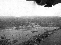
Регистрационный номер: G-ABTL [15] SINGAPORE: This view, taken from the Astraea, shows the reclaimed ground to be used as an airport.
-
Flight 1933-11 / Flight
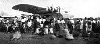
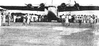
Регистрационный номер: G-ABTL [15] AT SOURABAYA: The business of adjustments, refuelling, etc., when Astraea was at Sourabaya, Java, caused considerable interest amongst the native population.
-
Flight 1933-11 / Flight
Регистрационный номер: G-ABTL [15] Maj. Brackley (fourth from right) and Capt. J. L Prendergast (third from right) with party at Batavia.
-

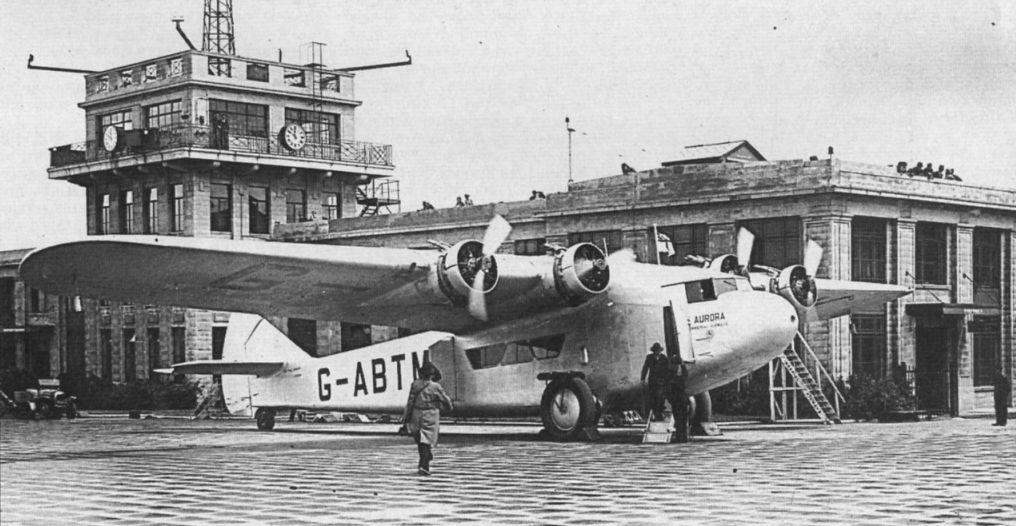
Aeroplane Monthly 1980-11 / R.Williams - Atalanta (2)
Регистрационный номер: G-ABTM [12], DG454 [12], VT-AEG [12] Atalanta G-ABTM, Aurora at the SBAC Display at Hendon on June 24, 1933, just prior to being delivered to Indian Trans-Continental Airways Ltd in August.
-
Aeroplane Monthly 1986-06 / J.Stroud - Wings of Peace
Регистрационный номер: G-ABTM [12], DG454 [12], VT-AEG [12] G-ABTM Aurora at Croydon before departure for India and re-registration as VT-AEG.
-

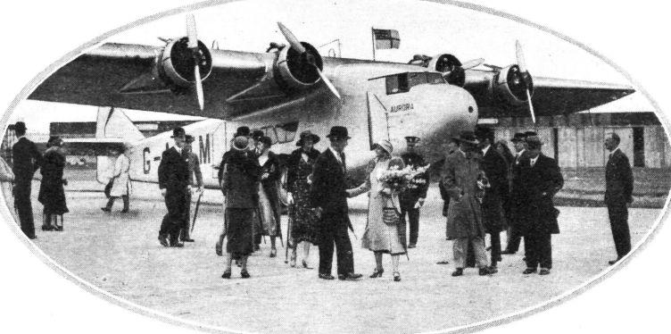
Flight 1933-07 / Flight
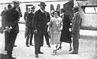
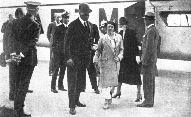
Регистрационный номер: G-ABTM [12], DG454 [12], VT-AEG [12] The Countess of Willingdon, wife of the Viceroy of India, disembarking at Croydon from the Imperial Airways Atalanta type four-engined monoplane at the conclusion of her flight from India.
-
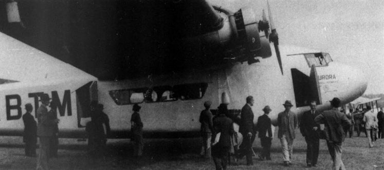
Flight 1933-07 / Flight Advertisements
Регистрационный номер: G-ABTM [12], DG454 [12], VT-AEG [12] The Royal party leaving the Aurora.
-
Flight 1934-04 / Flight
Регистрационный номер: VT-AEG [12], DG454 [12], G-ABTM [12] COMMERCIAL AND PRIVATE ENTERPRISE: Imperial Airways Armstrong-Whitworth airliner Aurora (pilot, Capt. Egglesfield) alighting on the Kuala Lumpur Flying Club's aerodrome, with the homeward mail, on March 11. This aerodrome is now one of the halting places on the Imperial air route.
-

Aeroplane Monthly 1986-06 / J.Stroud - Wings of Peace
Регистрационный номер: VT-AEG [12], DG454 [12], G-ABTM [12] Aurora, as VT-AEG, at Penang.
-
Flight 1935-04 / Flight Advertisements
Регистрационный номер: VT-AEG [12], DG454 [12], G-ABTM [12] The Imperial Airway's Liner Aurora of the Atalanta class about to leave Akyab, Burma.
-
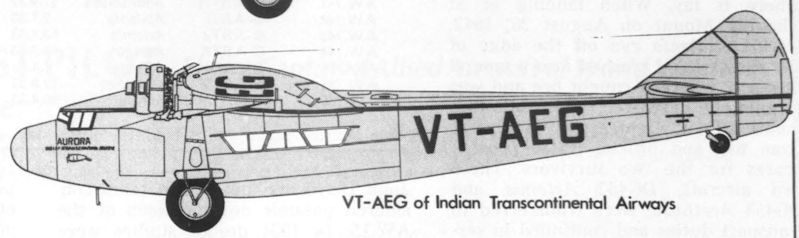
Aeroplane Monthly 1980-11 / R.Williams - Atalanta (2)
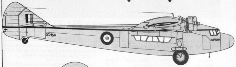
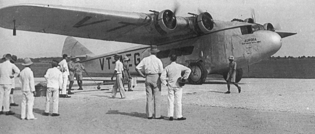
Регистрационный номер: VT-AEG [12], DG454 [12], G-ABTM [12] Atalanta VT-AEG was originally G-ABTM. After several years service with Indian Trans-Continental Airways Ltd it was impressed into service with the Indian Air Force at DG454.
-
Aeroplane Monthly 1980-11 / R.Williams - Atalanta (2)
Регистрационный номер: DG454 [12], G-ABTM [12], VT-AEG [12] Atalanta G-ABTM in its final guise as DG454 with the Indian Air Force, still bearing its original name, Aurora, wrongly applied as DC454.
-
Flight 1933-08 / Flight
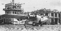
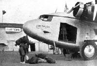
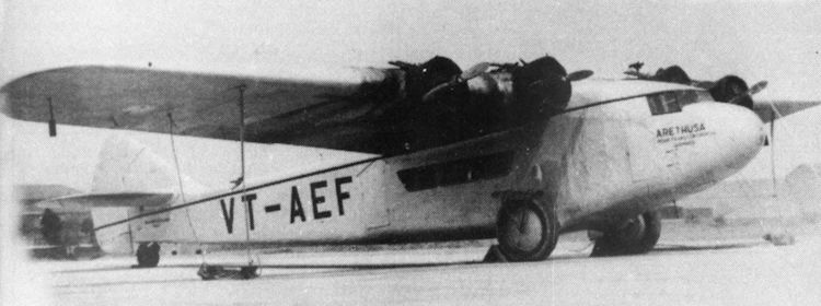
Регистрационный номер: VT-AEF [29], G-ABPI [29] THE NATURALISED INDIAN: The Armstrong-Whitworth airliner Arethusa, now operated over the Indian section by Indian Transcontinental Airways.
-
Flight 1933-08 / Flight
Регистрационный номер: VT-AEF [29], G-ABPI [29] THE KARACHI-CALCUTTA AIR MAIL: The accompanying illustrations show incidents in connection with the first air mail service between Karachi and Calcutta, which was inaugurated on July 7. Our picture shows the Armstrong-Whitworth Arethusa, of Indian Trans-Continental Airways, unloading mails from Calcutta at Karachi on the homeward journey on July 12.
-
Flight 1935-02 / Flight Advertisements
Регистрационный номер: VT-AEF [29], G-ABPI [29] The Arethusa, an Imperial Airway's Liner of the Atalanta class at Rangoon.
-
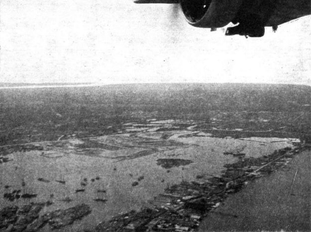
Flight 1936-04 / Flight
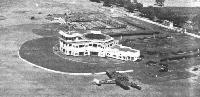
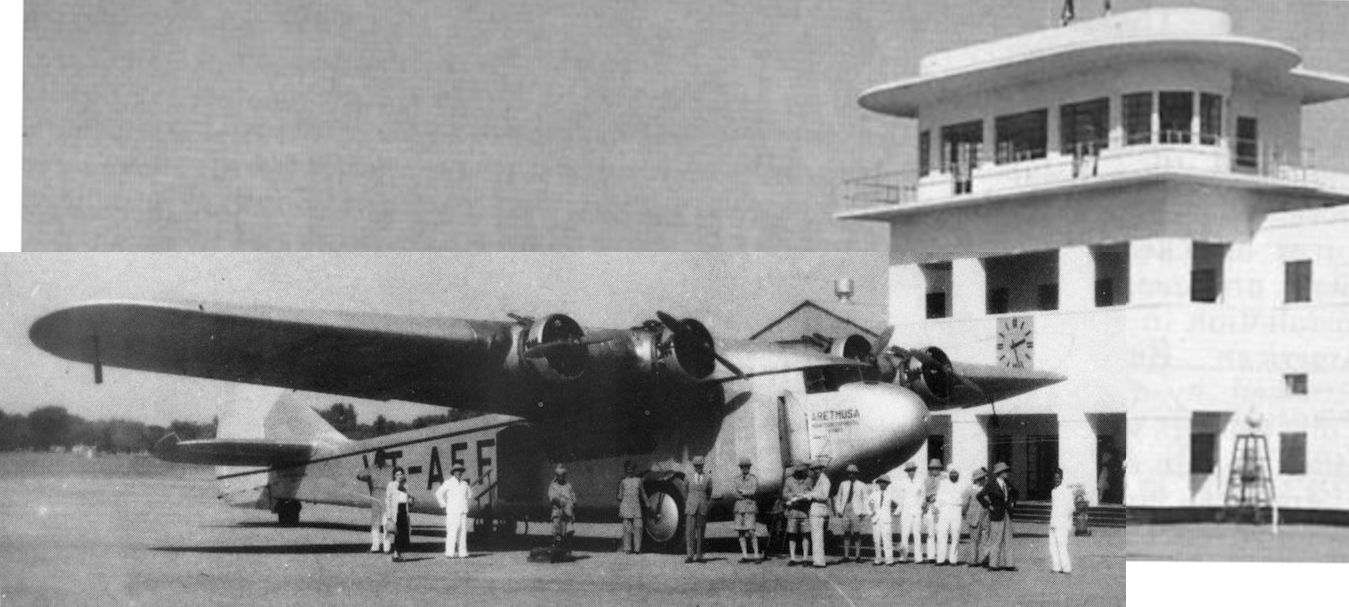
Регистрационный номер: VT-AEF [29], G-ABPI [29] INDIA'S MODEL AIRPORT BUILDING: This aerial picture, taken by Indian Air Survey and Transport, clearly shows the design of the New Delhi airport building, which was opened by H.E. Lord Willingdon on February 15. It is particularly interesting since it will be the model for several others which are to be built in India and forms a concrete result ot travels of Mr. R. T. Russel and Capt. A. G. Wyatt, who were responsible for the design.
-

Aeroplane Monthly 1974-03 / P.Moss - Wings for the Empire (3)
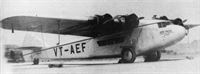
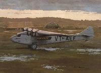
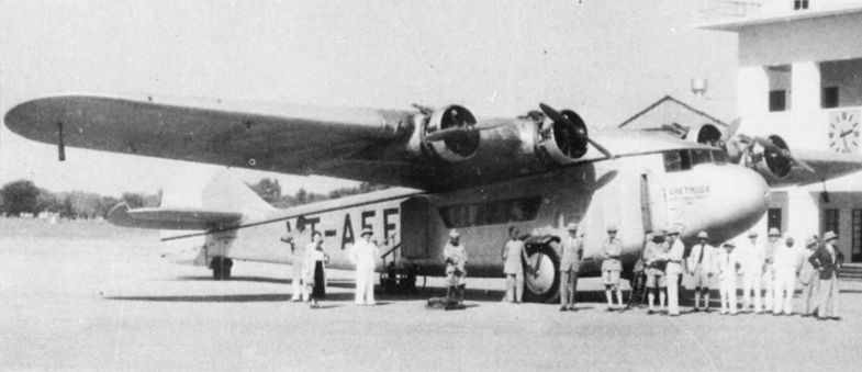
Регистрационный номер: VT-AEF [29], G-ABPI [29] A.W.15 VT-AEF, Arethusa, ex G-ABPI, probably at New Delhi.
-

Aeroplane Monthly 1980-11 / R.Williams - Atalanta (2)
Регистрационный номер: VT-AEF [29], G-ABPI [29] The prototype A.W.XV Atalanta, G-ABPI at Willingdon Airport, Delhi, in service with Indian Trans-Continental Airways Ltd as VT-AEF.
-
Aeroplane Monthly 1980-11 / R.Williams - Atalanta (2)
Регистрационный номер: VT-AEF [29], G-ABPI [29] Another view of the prototype Atalanta, originally G-ABPI, seen here as VT-AEF with ITCA.
-
-

Flight 1932-07 / Flight
THE TAIL WHEEL: This is of the castor type, and has a very short travel. Details of the tail-trimming gear can also be seen.
-
Flight 1932-07 / Flight
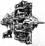
THE ARMSTRONG-SIDDELEY "DOUBLE MONGOOSE": At a normal speed of 2,000 r.p.m. it develops 340 h.p. at 4,000 ft. altitude. Max. power is 375 h.p. at 2,200 r.p.m.
-
Aeroplane Monthly 1986-06 / J.Stroud - Wings of Peace
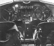
The flight deck of an A.W.XV.
-
Flight 1932-12 / Flight
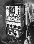
Marconi Type A.D. 37A/38A, combined medium and short wave transmitter and receiver and the Marconi-Robinson directional attachment, to be installed in the first four Armstrong-Whitworth "Atalanta" aircraft engaged on the Cairo-Cape Town air route.
-
Aeroplane Monthly 1986-06 / J.Stroud - Wings of Peace
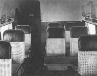
The cabin, looking aft
-
Flight 1933-08 / Flight Advertisements
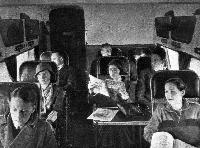
THE sound-proof cabin of the Atalanta is light and roomy with a good view from its windows. Its ventilation and temperature are easily and effectively controlled. Nine chair seats afford the utmost comfort for long journeys and, by means of a simple adjustment, can be arranged to provide a restful semi-reclining position with ample support for head and shoulders. There is accommodation for personal belongings in the wall recesses, and folding tables are an added convenience.
-

Air-Britain Archive 1982-02
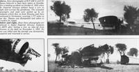
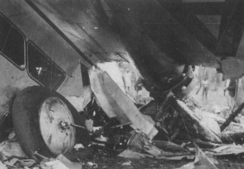
Регистрационный номер: G-ABPI [29], VT-AEF [29] View of the crashed prototype at Whitley Abbey.
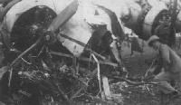
Clearly G-ABPI having engines and fittings removed while the rapidly approaching gentleman looks ready to remove some of the photographer's fittings! Readers should not find it too hard to locate the place and date.
G-ABPI The Atalanta accident was due to fuel starvation on take-off as a result of an experimental fuel vent system malfunctioning. -
Aeroplane Monthly 1980-10 / R.Williams - Atalanta (1)
Регистрационный номер: G-ABPI [29], VT-AEF [29] View of the crashed prototype at Whitley Abbey.
-
Aeroplane Monthly 1985-09 / Personal album
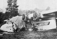
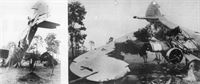
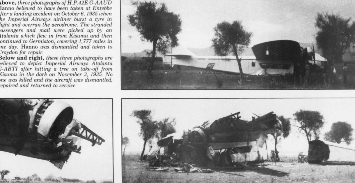
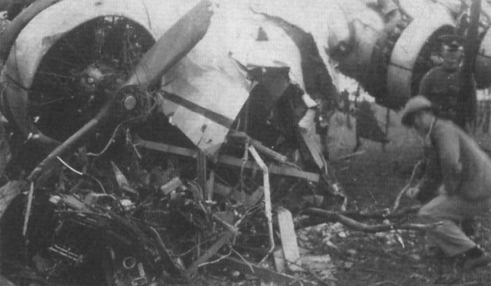
Регистрационный номер: G-ABTI [7] These three photographs are believed to depict Imperial Airways Atalanta G-ABTI after hitting a tree on take-off from Kisumu in the dark on November 3, 1935. No one was killed and the aircraft was dismantled, repaired and returned to service.
-
Aeroplane Monthly 1980-11 / R.Williams - Atalanta (2)
Регистрационный номер: G-ABTJ [4] Atalanta G-ABTJ, Artemis after stalling on takeoff from Pietersburg Aerodrome on February 10, 1936. Amazingly, this heap of firewood flew again, was later impressed into Indian Air Force service and was finally scrapped in 1944.
-
Aeroplane Monthly 1985-11 / Skywriters
Регистрационный номер: G-ABPI [29], VT-AEF [29] Capt Spafford's photograph of the Atalanta in which he crashed on February 10, 1936.
-

Aeroplane Monthly 1985-11 / Skywriters
Регистрационный номер: G-ABPI [29], VT-AEF [29] -
Flight 1933-12 / Flight Advertisements
Регистрационный номер: G-ABPI [29], VT-AEF [29] This photograph is composed entirely of SKYBIRD constructive models, with accessories, and shows the latest addition to this famous series of 1/72nd scale models - the A.W. "ATALANTA" with four perfect replicas of the 10-cylinder Siddeley Serval Radial Engines.
-
Aeroplane Monthly 1986-06 / J.Stroud - Wings of Peace
Регистрационный номер: VT-AEF [29], G-ABPI [29] G-ABPI after becoming Indian Transcontinental Airways’ VT-AEF Arethusa.
-
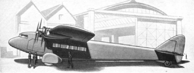
Flight 1931-02 / Flight
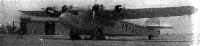
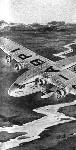
FOR THE AFRICAN AIR ROUTE: The "AW. XV" four-engined monoplane, which is being built for Imperial Airways by Armstrong-Whitworth, Ltd. It has four Armstrong-Siddeley "Double-Mongoose" engines.
-
-
Flight 1936-02 / Flight Advertisements
Регистрационный номер: G-ABPI [29], VT-AEF [29] -

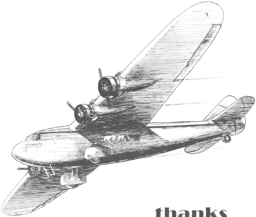
Aeroplane Monthly 1988-12 / P.Masefield - Wren
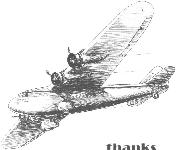
One of Wren's early illustrations appeared in the January 1933 issue of W. E. Johns’ Popular Flying magazine. Though he had already developed a style as a caricaturist, there is no evidence of it in this artwork.
-
-
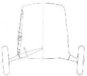
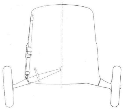
Flight 1932-07 / Flight
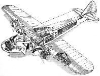
REDUCING UNDERCARRIAGE DRAG: Schematic representation of how most of the undercarriage is "buried" inside the fuselage.
-
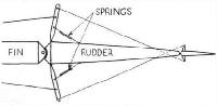
Flight 1932-07 / Flight
THE SERVO RUDDER ARRANGEMENT: For small angles the rudder is operated direct. For larger angles the Servo rudder comes into action.
-
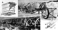
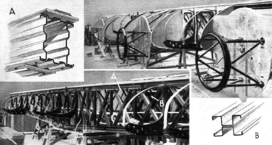
Flight 1932-07 / Flight
The front spar, with bearers for engines and petrol tanks. The insets show sections of spar booms and ties.
-

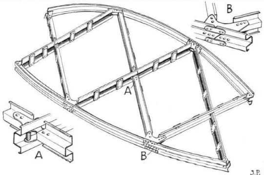
Flight 1932-07 / Flight
THE METAL RIBS: These are used in the central portion of the wing only, the other ribs being of wood.
-
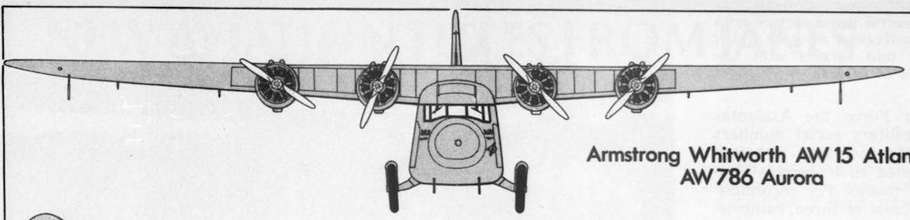
Flight 1932-07 / Flight
A.W.XV. 4 Double Mongoose Engines
-
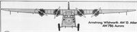
Aeroplane Monthly 1980-11 / R.Williams - Atalanta (2)
Armstrong Whitworth AW 15 Atlanta AW786 Aurora
-
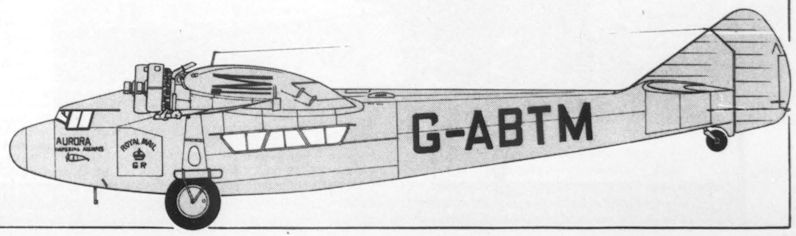
Aeroplane Monthly 1980-11 / R.Williams - Atalanta (2)
G-ABTM of Imperial Airways


- Фотографии