Варианты
- Fairey - Fairey III - 1917 - Великобритания
- Fairey - Fairey IIIF - 1926 - Великобритания
- Fairey - Gordon / Seal - 1931 - Великобритания
Семейство Fairey III
Появившийся еще в 1917 году самолет Fairey IIIF даже в 1941 году находился в эксплуатации, что говорит об удачности его конструкции. В конце 1917 года гидросамолет Fairey N.10 был подвергнут переделке - в результате появился самолет сухопутного базирования Fairey IIIA. Авиация британского флота разместила заказ на 50 двухместных бомбардировщиков корабельного базирования Fairey IIIA, которые должны были прийти на смену самолетам Sopwith 1 1/2-Strutter. Первый серийный Fairey IIIA поднялся в воздух в Нортхольте в июне 1918 года, однако конец Первой мировой войны не дал самолету продемонстрировать свой потенциал, а в 1919 году машина была объявлена устаревшей.
Другой вариант, Fairey IIIB, имел такой же фюзеляж и горизонтальное хвостовое оперение, но отличался крылом и килем большей площади. В малосерийное производство он все же поступил и даже некоторое время использовался для поиска мин и минных банок. Было собрано 25 самолетов, первый из них совершил полет в августе 1918 года. Как и Fairey IIIA, самолет Fairey IIIB оснащался двигателем Sunbeam Maori мощностью 260 л. с. (194 кВт). Известно, что на заводе для серийных Fairey IIIB было выделено 60 серийных номеров, но не менее 30 машин на стапеле были переоборудованы в модификацию Fairey IIIC, который был в целом аналогичен Fairey IIIB, но имел бипланную коробку неравного размаха - по типу Fairey IIIA. Значительное улучшение летных характеристик новой машины было обусловлено использованием двигателя Rolls-Royce Eagle VIII мощностью 375 л. с. (280 кВт). Первая серийная поставка была осуществлена в ноябре 1918 года - самолеты получила 229-я эскадрилья, дислоцировавшаяся в Грейт-Ярмуте, графство Норфолк, а другие машины ушли в 267-ю эскадрилью на Мальту. Однако единственный случай боевого применения самолета был зафиксирован в районе действия вторгнувшегося на север Советской России экспедиционного корпуса - в 1919 году машины были переброшены туда на борту авиатранспорта "Пегасус". Двигатель Eagle оказался весьма надежным, такой же надежной была и эксплуатация Fairey IIIC, но всего было собрано только 35 таких самолетов - с 1921 года они стали поступать на вооружение британских ВВС и заменили ранее выпущенные машины. Несколько Fairey IIIC пережили военное лихолетье и впоследствии использовались в гражданской авиации: одна машина, оснащенная сдвижными фонарями и топливными баками увеличенной емкости, была отправлена на Ньюфаундленд в марте 1920 года - ее предполагалось использовать в трансатлантическом перелете, который, впрочем, не состоялся. Длительное время он использовался фирмой "Fairey" в качестве демонстратора двухместного гидросамолета, но после аварии в Канаде был возвращен на завод для ремонта и последующей перепродажи.
Fairey IIID, ставший дальнейшим усовершенствованием модификации Fairey IIIC, обрел ряд существенных усовершенствований. В своем сухопутном варианте он был первым самолетом, оснащенным шасси с масляно-воздушным амортизатором. Fairey IIID поднялся в воздух в августе 1920 года. Министерство авиации в соответствии со Спецификацией 38/22 разместило заказ на данный самолет, всего же британские ВВС закупили 207 самолетов, из которых 56 имели двигатели Rolls-Royce Eagle, а остальные оснащались различными вариантами Napier Lion мощностью 450 л. с. (336 кВт). Большинство Fairey IIID эксплуатировалось как поплавковые гидросамолеты в британских ВМС - с базированием на приморских аэродромах или применялись с катапульт с борта боевых кораблей. Первыми в 1924 году самолеты Fairey IIID получили 441-е и 444-е звенья. 30 сентября 1925 года один из данных гидросамолетов, принадлежащих морской авиации британского флота, впервые совершил взлет с борта корабля с катапульты в открытом море.
В авиации британских ВМС Fairey IIID заменили собой Parnall Panther и Supermarine Seagull, они состояли на вооружении девяти подразделений и базировались начиная от авиабазы Льючарс в шотландской области Файф до базы на Дальнем Востоке. Самолеты Fairey IIID на флотской службе были обычно трехместными, но было построено и небольшое количество двухместных учебно-тренировочных, а также несколько двухместных вариантов для буксировки мишеней. Важный след в истории Королевских ВВС Великобритании оставил сухопутный вариант Fairey IIID - в 1926 году четыре такие машины перелетели из Гелиополиса в Кейптаун и вернулись в Великобританию через Грецию, Италию и Францию, причем без каких-либо механических поломок. Самолеты преодолели расстояние в 22371 км, а в Абукире были переделаны в гидросамолеты, после чего вылетели домой - в направлении Ли-он-Солент.
В ВВС единственной эскадрильей, получившей Fairey IIID, стала 202-я эскадрилья, сформированная на базе 481-го авиаотряда (звена) авиации Королевских ВМС Великобритании. На Fairey IIID были получены и экспортные заказы. Один из них - от Австралии на шесть самолетов, оснащенных двигателями Eagle, первый передан в Хэмбле заказчику 12 августа 1921 года, а третий австралийский Fairey IIID совершил в 1924 году перелет по периметру побережья Австралии, преодолев расстояние 13 789 км и завоевав Кубок Британии. Одиннадцать Fairey IIID были поставлены португальскому правительству, первые четыре машины имели двигатели Eagle, а остальные - двигатели Napier Lion. Два самолета были потеряны во время попыток дальних перелетов, но третий завершил путешествие из Лиссабона в Рио-де-Жанейро. Два самолета Fairey IIID были проданы в Швецию, а четыре заказала авиация голландских ВМС - для эксплуатации в Голландской Вест-Индии. В 1924 году гражданский вариант Fairey IIID с двигателем Rolls-Royce Eagle IX был модифицирован для применения в качестве санитарного самолета в Британской Гвиане, а другой гражданский самолет использовался в 1927 году в качестве замены четырехместного DH.50J на авиамаршруте между Хартумом и Кисуму - через месяц он попал в аварию, его ремонт был признан нецелесообразным.
<...>
Описание:
- Семейство Fairey III
- Flight, September 1920
THE AIR MINISTRY SEAPLANE (AMPHIBIAN) COMPETITION - Flight, August 1921
THE FAIREY TYPE IIID SEAPLANE - Flight, January 1922
THE NEW FAIREY LONG-DISTANCE SEAPLANE - Flight, July 1923
Gothenburg International Aero Exhibition 1923
Фотографии
-
Air Enthusiast 2006-03 / The Roundels File
Регистрационный номер: S1103 [3] Fairey IIID S1103 (c/n F841) of the Cape Flight, led by Wg Cdr H W Pulford obe dfc. Cape Flight aircraft (S1102 to S1108) assembled at Northolt, London, November 1925 for a long-distance formation 'flag-waving' flight, March to June 1926. It flew in a landplane configuration Cairo-Cape-Cairo then converted to floatplane at Aboukir, Egypt, for return flight to Lee-on-Solent, Hampshire. Having completed the 13,900 mile (22,370km) flight, it then donned undercarriage again to appear at the RAF Pageant, Hendon, London, early July 1936. S1103 ended its days with the School of Naval Co-operation at Lee-on-Solent in 1929.
-
Air Pictorial 1999-05
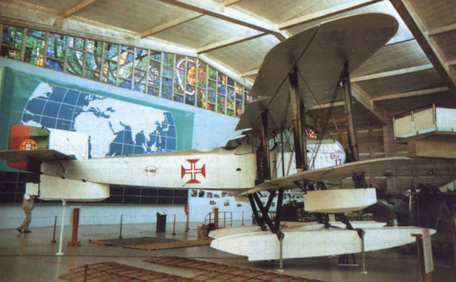
The Fairey IIID in the Lisbon Maritime Museum
-
Aeroplane Monthly 1996-08
James Hare’s question on Almirante Gago Coutinho has brought replies from Jim Parker, M.G. Moore, Richard Hewitt, N.D. Welch, Alf Godman, Colin Noad, Maurice Gordon-Edgley and Arae Amesen. The information has been sent to Mr Hare, but for the benefit of others the very brief story is that it was an Atlantic, not Pacific, flight from Lisbon to Rio via the Cape Verde islands, St Paul Rocks and Fernando Noronha islands between March 30 and June 17, 1922, by Captains Gago Coutinho and Sacadura Cabral, navigator and pilot respectively. In all, three aircraft were involved, two of which crashed; each time a replacement had to be shipped from Portugal. The aircraft were Fairey IIIDs and the survivor, shown, is displayed in the Museum de Marinha in Lisbon.
-
Aviation Historian 40 / J.Kightly, R.Reis - The power of three
The original surviving Fairey IIID, c/n 402 Santa Cruz, is seen here preserved at the Museu de Marinha de Lisboa (Portuguese Naval Museum), while an accurate replica constructed by Portuguese aerospace company OGMA for the 50th anniversary of the crossing is at the Museu do Ar at Alverca.
-
Aviation Historian 40 / J.Kightly, R.Reis - The power of three
Fairey IIID c/n F400 prepares to depart Portugal for South America in March 1922. Colourisation of original photograph by RICHARD J. MOLLOY.
-
Aviation Historian 40 / J.Kightly, R.Reis - The power of three
Several monuments commemorating Cabral and Coutinho’s 1922 flight take pride of place in Portugal, including this remarkably accurate full-size sculpture of the aircraft by Soares Branco at the departure point on the waterfront at Lisbon. Another full-size steel sculpture is located at Sao Bras de Alportel in the Algarve.
-
Мировая Авиация 34
6 июня 1918г.: первый из удачного семейства морских легких бомбардировщиков Fairey III - Fairey IIIA - поднялся в воздух в Нортхолте.
-
Flight 1922-12 / Flight
Регистрационный номер: N9451 [2] The Fairey Series IIID, converted to a land machine by the substitution of long-travel oleo undercarriage for floats. A 450 h.p. Napier "Lion" is fitted to this machine. Aeroplane has variable camber wings.
-
Flight 1925-04 / Flight
A New Fairey 3D: Produced originally as a seaplane, in which form it was used by Wing-Commander Coble for his round-Australia flight, the Fairey 3D is also used as a land machine, in which guise it is shown in our photograph. A special Fairey oleo undercarriage is fitted. The engine is a Napier "Lion."
-
Aeroplane Monthly 1978-08 / Personal album
Регистрационный номер: S1102 [2], S1103 [3], S1104, S1105 [2] The RAF’s first long-distance formation flight, and the first to South Africa, was made by these four Fairey IIIDs, serialled (front to rear) S1103 (c/n F841), S1102 (F840), S1105 (F843), and S1104 (F842). Formed as the Cape Flight at Northolt in November 1925, the aircraft completed a successful Cairo-Cape-Cairo-England trip between March 1 and June 21, 1926, led by Wg Cdr C. W. H. Pulford, OBE, AFC. Flying as landplanes for the 11,000 mile Cairo-Cape-Cairo trip, and as seaplanes for the return flight to Lee-on-Solent, the four aircraft suffered only minor troubles, and their original Napier Lion VA engines were used throughout the journey.
-
Flight 1926-06 / Flight
Регистрационный номер: S1103 [3] THE R.A.F. CAIRO - CAPE - CAIRO FLIGHT: This photograph shows the four Fairey machines with Napier "Lion" engines being refuelled with "Shell" at Johannesburg.
-
Flight 1926-07 / Flight
AT THE R.A.F. DISPLAY: During the afternoon the four Fairey IIID biplanes, piloted by Wing-Corn. Pulford and his companions, recently back from their Cairo-Cape-Cairo flight flew over the aerodrome and saluted the Royal Enclosure.
-
Aeroplane Monthly 1987-08 / A.Lumsden, T.Heffernan - Per Mare Probare (5)
Регистрационный номер: N10 [2] The Sunbeam Maori-powered F.128 seaplane, more commonly known by its serial number, N10.
-
Aeroplane Monthly 1994-03 / P.Jarrett - Fairey IIIF (1)
Регистрационный номер: N10 [2] The original ancestor of Fairey’s long-serving “III” series was this unassuming seaplane of 1917, N10/F.128, designed to Admiralty Specification N.2(a).
-
Air-Britain Aeromilitaria 1982-03
The Fairey IIIB was the first type of seaplane operated by Argus and was hoisted in and out by a crane mounted immediately aft of the hangar on the quarterdeck.
-
Aeroplane Monthly 1987-08 / A.Lumsden, T.Heffernan - Per Mare Probare (5)
The Fairey IIIB, with its long upper wing overhangs, was designed as a bomber to fulfil Admiralty Specification N.2(b).
-
АвиаМастер 1999-03 / В.Куликов - Славяно-британский авиакорпус на севере России /Белое дело/ (2)
Регистрационный номер: N9230 "Фэйри" IIIC. На этих машинах воевали английские морские летчики в северной России.
-
Aeroplane Monthly 1994-03 / P.Jarrett - Fairey IIIF (1)
Регистрационный номер: N2255 The typically boxy lines of the earlier variants of the “III” series are well portrayed in this view of IIIC N2255, probably the second to be built on the IIIB production lines.
-
Мировая Авиация 45
Май 1919 года: впервые свежие газеты "Ивнинг Ньюс" стали доставляться ежедневно гидросамолетом Fairey IIIC, взлетавшим с Темзы и приводнявшимся у побережья Кента.
-
Aeroplane Monthly 1999-11 / D.Baker - A disturbance in the Dardanelles /Inter-war RAF/
Регистрационный номер: N9499 [2] Towing Fairey IIID Mk I N9499 before recovery aboard its mother ship, possibly off Constantinople.
-
Aeroplane Monthly 1999-11 / D.Baker - A disturbance in the Dardanelles /Inter-war RAF/
Регистрационный номер: N9499 [2] Fairey IIID Mk I N9499 served with 267 Sqn in HMS Ark Royal from October 1922 to April 1923 and was also with HMS Argus.
-
Flight 1920-10 / Flight
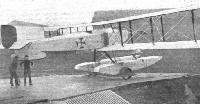
Регистрационный номер: G-EALQ [7] AIR CONFERENCE VISIT TO WADDON: The Fairey Amphibian taxying in
-
Flight 1920-09 / Flight
Регистрационный номер: G-EALQ [7] THE FAIREY III AMPHIBIAN: Three-quarter front view
-
Flight 1920-09 / Flight
Регистрационный номер: G-EALQ [7] THE AIR MINISTRY COMPETITION: Three-quarter rear view of the Fairey III Amphibian float seaplane, 450 h.p. Napier "Lion" engine
-
Flight 1920-09 / Flight
Регистрационный номер: G-EALQ [7] THE FAIREY III AMPHIBIAN: View of tail, tail float and skid
-
Aeroplane Monthly 1987-08 / A.Lumsden, T.Heffernan - Per Mare Probare (5)
Регистрационный номер: G-EALQ [7] Another view of N10, which Fairey bought back from the Admiralty after the Armistice and registered G-EALQ for use as a racing and communications aircraft. It is seen here being taxied by Lt-Col Vincent Nicholl at Cowes before the 1919 Schneider Trophy contest.
-
Flight 1925-11 / Flight
Регистрационный номер: G-EALQ [7] THE 1919 SCHNEIDER CUP CONTEST: Another British entry, the Fairey seaplane (Napier "Lion"), piloted by Lieut.-Col. Vincent Nicholl.
-
Flight 1929-09 / Flight
Регистрационный номер: G-EALQ [7] AT BOURNEMOUTH: THIS VIEW SHOWS THE ONE OF FOUR COMPETITORS IN THE 1919 CONTEST STARTING OFF THE PIER. VINCENT NICHOLL ON THE FAIREY
-
Flight 1924-05 / Flight
THE FLIGHT AROUND AUSTRALIA: The photographs above show the Fairey III-D seaplane, with Rolls-Royce "Eagle IX" engine, on which Wing-Commander S. J. Goble, D.S.O., O.B.E., D.S.C., and Flying Officer L. E. MacIntyre, of the Royal Australian Air Force, have just succeeded in completing their 9,000 miles flight around Australia. The performance is one worthy of ranking among the foremost flights ever made, and reflects the greatest credit not only on the gallant officers who made it, but also on the machine and engine. The photographs show the machine at Point Cook, near Melbourne.
-
Flight 1921-08 / Flight
THE FAIREY TYPE IIID SEAPLANE: Our photograph shows the "A.N.A.2," the second machine to be finished for the Australian Naval Air Service. Except for minor alterations this machine is similar to the standard type IIID described herewith.
-
Flight 1921-08 / Flight
CHRISTENING THE FAIREY IIID-ROLLS: At the moment of the breaking of the bottle of champagne on the propeller boss, by Mrs. A. M. Hughes, wife of the Australian Premier.
-
Flight 1921-08 / Flight
ON THE SLIPWAY: The Fairey "A.N.A.1" shortly before the launching.
-
Flight 1921-08 / Flight
THE FAIREY "A.N.A.1": The machine being launched from its slipway.
-
Flight 1925-02 / Flight
The Fairey-Napier III.D at Work: The photograph herewith depicts one of the Fairey III.D seaplanes fitted with a 450 h.p. Napier "Lion," of the R.A.F., carrying out duties at Malta. This type of machine is used with very satisfactory results in all parts of the world. Recently one of these machines was stationed at Hong Kong for five months, during which time there was not a single engine failure or forced landing. On another occasion in the Dardanelles area one of these seaplanes carried out a continuous flight of 500 3/4 miles in 6 3/4 hours, with a load of over 2 1/4 tons, when the petrol consumption was only 15 1/4 gals, per hour. It was for this type of machine that the Dutch Government placed a large order with the Fairey Aviation Co., as previously reported in "Flight."
-
Flight 1921-08 / Flight
THE FAIREY "A.N.A.1": Three views of the machine in flight, carrying as passengers General Seely and General Sir Sefton Brancker.
-
Flight 1924-08 / Flight
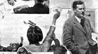
SECOND IN THE KING'S CUP RACE: 3, Capt. Norman Macmillan crossing the finishing line on his Fairey III.D (Napier "Lion"). 4, Capt. Macmillan, complete with pipe
-
Air-Britain Aeromilitaria 1983-01
Регистрационный номер: S1108 Seen flying over Malta in 1928-29 is the last Fairey IIID built for the FAA, S1108 (Fleet No.40) of No.440 Flight. This three-seat spotter reconnaissance seaplane was powered by the 450 h.p. Napier Lion engine.
-
Мировая Авиация 123
Первоначально обозначенный "IIIC (усовершенствованный)", Fairey IIID выпускался в вариантах Mk I и Mk II.
-
Air-Britain Aeromilitaria 1989-02
Aircraft used by No. 202 Squadron in earlier days included this Fairey IIIDs off Malta in the 1920s.
-
Aeroplane Monthly 1986-03 / Personal album
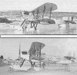
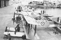
Регистрационный номер: N9568 [2], N9630 [9], S1078, S1105 [2], G-EBKE [9] A flight of four Fairey IIIDs put up by 202 Squadron RAF at Malta circa 1929-30. The four aircraft are N9630, S1078, S1105 and N9568. The aircraft in the foreground later became G-EBKE and in 1924 was modified for Real Daylight Balata Estates in British Guiana for ambulance duties. The IIID was the mainstay of the FAA during the second half of the Twenties, until the type was succeeded by the Fairey IIIF. The IIID was a reliable spotter-reconnaissance land/seaplane and could be flown off carriers, from shore stations and was even catapulted from warships.
-
Flight 1927-03 / Flight
Регистрационный номер: S1102 [2] Fairey IIID (Napier "Lion"). This Fairey seaplane type has long been used for work with the Fleet, and it also has a considerable record of fine flights. One in particular that is familiar being the R.A.F. flight from Cairo to the Cape, the return to Cairo and then on to England. The IIID is adaptable to both seaplane and land 'plane service. It may, perhaps, be regarded as one of the standard seaplane types for its specific purpose, i.e., fleet reconnaissance work. It is used by No. 440 Flight (H.M.S. Hermes), No. 441 (H.M.S. Eagle), No. 442 (Leuchars), No.443 (H.M.S. Furious), No. 444 (H.M.S. Vindictive), and No. 481 (Malta).
-
Aeroplane Monthly 1986-03 / Personal album
Регистрационный номер: N9568 [2], N9753 Top: Fairey IIID N9568 of 202 Sqn RAF at Malta circa 1929-30. Bottom: Fairey IIID N9753 of 202 Sqn RAF at Malta circa 1929-30.
-
Aeroplane Monthly 1977-03 / Personal album
Регистрационный номер: N9495 The liner SS Berengaria passes the Calshot slipway as a handling party prepare to beach Fairey IIID seaplane N9495, from the first production batch of 50 aircraft to Specification 38/22. The powerplant was the 365 h.p. Rolls-Royce Eagle VIII, although the 450 h.p. Napier Lion was also fitted in later batches. First flown in August 1920, the IIID was a highly successful aircraft, 227 examples being produced before production ceased in 1926.
-
Flight 1925-06 / Flight
FAIREY SEAPLANES FOR HOLLAND: As previously reported in "Flight," the Fairey Aviation Co., Ltd., of Hayes, recently delivered to the Dutch Government a batch of Series III seaplanes (Napier "Lion" engines). The above photograph shows the machines anchored at Hamble, from which place they were flown to Holland by Dutch pilots.
-
Aeroplane Monthly 1987-08 / A.Lumsden, T.Heffernan - Per Mare Probare (5)
Регистрационный номер: N9235, N9237 The Fairey IIIC was the first recognisable ancestor of the IIIF. Although too late to see service during World War One, the variant operated with the North Russian Expeditionary Force from Archangel in 1919.
-
Aeroplane Monthly 1987-08 / A.Lumsden, T.Heffernan - Per Mare Probare (5)
Регистрационный номер: N9464 Fairey IIID N9464 (c/n F.358) was one of the first production batch, ordered by the Air Ministry to Specification 38/22. Originally fitted with Rolls-Royce Eagle VIII engines, the aircraft of this batch were later converted to the more usual powerplant for the type, the Napier Lion.
-
Air Enthusiast 2006-03 / The Roundels File
Регистрационный номер: N9777 [3] Wearing the race number '3' Fairey IIID Mk.II N9777 was entered into the 1924 King's Cup air race and, flown by Capt Norman Macmillan, came second in the seaplane section. Delivered to the MAEE at Felixstowe in August 1924, it was 'prepped' for the race, which was staged at the seaplane base from the 12th of that month. After that it was refurbished by Fairey, ready for despatch to Malta.
-
Flight 1924-10 / Flight
Регистрационный номер: N9777 [3] AN INCIDENT IN THE KINGS CUP RACE. Two views of the Fairey III-D seaplane (450 h.p. Napier "Lion" engine) at Stranraer, on the occasion of the last King's Cup Race, August 12. Above, bringing the seaplane ashore. Below, the crowd watching the refueling operations - note the "Shells" on the shore.
-
Jane's All the World Aircraft 1980 / Encyclopedia of Aviation - Aircraft A-Z - v3
Fairey IIID used on the Cairo - Cape Town - Cairo flight.
-
Flight 1926-06 / Flight
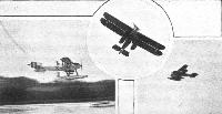
HOME FROM THE CAPE: Commander Pulford's squadron arrived at Lee-on-Solent on June 21 after having successfully flown from Cairo to the Cape and back, continuing on to England. The total distance covered is approximately 14,000 miles. In 1, are seen three of the four Fairey machines arriving over Lee-on-Solent, while in 2, one of the machines is seen touching "home waters," 3 shows three of the machines taxying up to the beach, while in 4, willing hands are beaching Commander Pulford's machine.
-
Air Enthusiast 2006-03 / The Roundels File
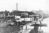
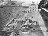
Регистрационный номер: N9630 [9], N9636, N9773, N9777 [3], G-EBKE [9] Former King's Cup air racer IIID Mk.II N9777 had arrived at Kalafrana, Malta, by January 1929 and joined 202 Squadron. It is illustrated on the slipway with stablemates N9630, N9636 and N9773. N9777 was involved in a landing accident in the bay on February 5, 1930, and was written off.
-
Flight 1926-09 / Flight
CAPE FLIERS AT NAPLES: This photograph shows the four Napier-engined Fairey III.D seaplanes re-fuelling with "Shell" at Naples on their flight from Cairo to Lee-on-Solent recently, this being the concluding stage of the Cairo-Cape-Cairo-England flight.
-
Air Enthusiast 1999-07 / J.Grant - Anti-clockwise
Регистрационный номер: A10-3 Fairey IIID A10-3 at Israelite Bay, WA. The isolated landing site was one of many surveyed by the crew.
-
Aeroplane Monthly 1980-02 / C.Baker - Fixing a Fairey
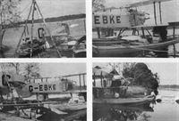
Регистрационный номер: G-EBKE [9], N9630 [9] Fairey IIID G-EBKE at Hamble a few months earlier.
-
Aeroplane Monthly 1980-02 / C.Baker - Fixing a Fairey
Регистрационный номер: G-EBKE [9], N9630 [9] THE FAIREY AMBULANCE SEAPLANE: Views of the Fairey III-D seaplane (Rolls-Royce "Eagle IX" engine), which has been specially fitted out as an ambulance for service in British Guiana. On the top, the "patient" is shown being hoisted up on the stretcher by means of a portable winch. In the bottom, the "patient" is safely stowed inside the fuselage, and the hinged fuselage-top is being closed down.
Fairey IIID G-EBKE, subject of Charles Baker’s article, was one of two British civil examples and was built to the order of Real Daylight Balata Estates Ltd for ambulance duties in British Guiana. This IIID began life as N9630 (c/n F.439), and was modified for civil use at Ramble in 1924. In order to carry a stretcher case and attendant the rear fuselage decking was hinged for access. Portholes were added and the aircraft equipped with radio. -
Aeroplane Monthly 1980-02 / C.Baker - Fixing a Fairey
Регистрационный номер: G-EBKE [9], N9630 [9] THE FAIREY AMBULANCE SEAPLANE: Views of the Fairey III-D seaplane (Rolls-Royce "Eagle IX" engine), which has been specially fitted out as an ambulance for service in British Guiana. General view of the machine ready for flight.
These Flight photographs were taken at Ramble during the latter part of 1924. G-ABKE was powered by a 360 h.p. Rolls-Royce Eagle IX. -
Flight 1925-07 / Flight
WITH THE MEDITERRANEAN FLEET AT GENOA: The two photographs were taken on the occasion of the visit of the Mediterranean Squadron of the British Fleet to Genoa, and they depict one of the Fairey seaplanes, attached to the Fleet, taking in a supply of "Shell" Aviation Spirit.
-
Flight 1927-06 / Flight
FLYING IN AFRICA: One of snapshots brought back to England by Mrs. Eliott-Lynn. 1, Loading mails into the Kisumu-Khartoum machine (Fairey IIID).
-
Flight 1927-06 / Flight
Регистрационный номер: G-EBPZ FLYING IN AFRICA: One of snapshots brought back to England by Mrs. Eliott-Lynn. 4, The Fairey IIID being hoisted on to the dock at Kisumu.
-
Air Enthusiast 2006-03 / The Roundels File
Регистрационный номер: N9451 [2] Fairey IIID Mk.I N9451 was issued to the Marine Aircraft Experimental Establishment at the Isle of Grain, Kent, in January 1921 for performance trials on its Eagle VIII and, later, Lion II engines. It moved to Lee-on-Solent, Hampshire, in late 1921 and carried out deck-landing trials on HMS 'Argus'. In July 1922 it was transferred to the Aeroplane & Armament Experimental Establishment at Martlesham Heath, Suffolk, and then to the Development Flight at Gosport, Hampshire. It was back with MAEE, but by then at Felixstowe, Suffolk, by October 1924. Despatched to Malta, it joined 481 Flight at Kalafrana, serving mid-1925 until mid-1926.
-
Flight 1923-08 / Flight
BRITAIN AT I.L.U.G.: This set of photographs, kindly supplied by the S.B.A.C., shows some of the British exhibits at the Gothenburg International Aero Exhibition, which has just closed. The Fairey III D, with Napier "Lion."
-
Flight 1925-01 / Flight
The Fairey III-D Amphibian Seaplane: We show here a "close-up" of this machine - which was described in "Flight" for October 16 last - showing the Rolls-Royce "Eagle IX" engine, Fairey-Reed metal tractor screw, and the float gear. This machine has been sent to British Guiana.
-
Aeroplane Monthly 1982-10 / B.Gunston - The classic aero engines (2)
The Fairey Series IIID seaplane. The machine shown here is fitted with a 360 h.p. Rolls-Royce "Eagle IX."
A Portuguese Navy Fairey IIID powered by a 360 h.p. Rolls-Royce Eagle IX. -
Jane's All the World Aircraft 1980 / Encyclopedia of Aviation - 1. Chronology
Fairey IIID Santa Cruz (13 March 1922).
-
Мировая Авиация 43
13 марта 1922г.. Португальские летчики Г. Коутинхо и С. Кабраль вылетели из Лиссабона на Fairey IIIC в первый полет над Южной Атлантикой. 16 июня они прибыли в Бразилию, но уже на третьем самолете IIID "Santa Cruz" (на снимке), две другие машины потерпели аварии на маршруте.
-
Flight 1935-06 / Flight
The Fairey IIID (Rolls-Royce "Eagle") in which Coutinho and Cabral made the first South Atlantic crossing in 1922. Behind it is another historical machine, a Schreck flying boat acquired by the Portuguese Naval Aviation Service in 1917.
Другие самолёты на фотографии: FBA Type A/B/C - Франция - 1913
-
Flight 1922-01 / Flight
The Fairey long-distance Seaplane: Three-quarter rear view.
-
Aviation Historian 40 / J.Kightly, R.Reis - The power of three
Bearing its construction number, F400, prominently on the aft fuselage, the first of Cabral and Coutinho’s three Fairey IIIDs used on the South Atlantic attempt undergoes instrument and equipment checks in flying attitude at Doca do Bom Sucesso in Belem, Lisbon, before departure. By this time the underwing fuel tanks had been deleted and relocated in the main floats.
-
Aviation Historian 40 / J.Kightly, R.Reis - The power of three
With engineers hard at work on its Rolls-Royce Eagle engine, Lusitania undergoes maintenance at Sao Vicente in Cape Verde in early April 1922, Cabral and Coutinho having decided that a technical stop was essential to the crossing’s viability. It was here that the pair hatched the plan to alight at the St Peter and St Paul Archipelago.
-
Aviation Historian 40 / J.Kightly, R.Reis - The power of three
With the Portuguese flag proudly raised above the cockpit of the third Fairey IIID used in the attempt, c/n F402, Cabral and Coutinho finally arrive at Rio de Janeiro on June 17, 1922.
-
Aviation Historian 40 / J.Kightly, R.Reis - The power of three
Artur de Sacadura Freire Cabral (left) and Carlos Viegas Gago Coutinho photographed beside the hangar containing the specially adapted Fairey IIID the pair used to launch the first aerial crossing of the South Atlantic in 1922. A distinguished naval geographer, Coutinho was 53 years old when he and Cabral undertook the 1922 flight.
-
Aviation Historian 40 / J.Kightly, R.Reis - The power of three
Cabral (left) and Coutinho in the cockpits of Fairey IIID c/n F400. Cabral’s cockpit is in the midships position, close to the aft cockpit, in which Coutinho is seen here. The second and third Fairey IIIDs used to complete the South Atlantic flight were of standard configuration, with the crew situated further apart.
-
Aviation Historian 40 / J.Kightly, R.Reis - The power of three
The aircraft was a completely standard IIID floatplane and was named Santa Cruz, as seen on the cowling at its official christening.
-
Flight 1922-01 / Flight
THE FAIREY LONG-DISTANCE SEAPLANE USED IN THE TRANSATLANTIC ATTEMPT: Under the lower plane may be seen large petrol tanks. These have now been removed, and tanks fitted in the floats Instead. Otherwise the machine remains as shown in the photograph.
-
Flight 1922-01 / Flight
The Fairey long-distance Seaplane: View of the machine taxying in after a flight.
-
Aviation Historian 40 / J.Kightly, R.Reis - The power of three
Named Lusitania in honour of the ancient region which became Portugal, Fairey IIID c/n F400 taxies past the distinctive 16th-century Torre de Belem on the River Tagus in Lisbon, the landmark famous as an embarkation and disembarkation point for Portuguese explorers.
-
Flight 1922-04 / Flight
The Lisbon-Rio Flight: The Fairey seaplane "Lusitania," Rolls-Royce "Eagle 8" engine, taxying.
-
Aviation Historian 40 / J.Kightly, R.Reis - The power of three
Replacement Fairey IIID c/n F401 awaits offloading from the stem of SS Bage at Fernando de Noronha on May 6. Given the serial “16”, this was a IIID, but fitted with the 62ft 9in (19-13m)-span extended upper wings of the IIIB, the lower wings retaining the IIID’s 46ft 1in (14-05m) span. A protective tarpaulin covers the forward fuselage.
-
Aviation Historian 40 / J.Kightly, R.Reis - The power of three
Another view of the Fairey being unloaded from SS Bage at Fernando de Noronha. The difficulties of such a task in inclement weather are apparent, especially for the unloading crew, but the weather held long enough for the delivery to be completed in calm conditions. Apart from the unequal-span wings, this was a standard IIID.
-
Flight 1921-08 / Flight
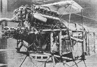
The Fairey Type IIID Seaplane: Front portion of the fuselage, showing Rolls-Royce "Eagle" engine.
-
Flight 1921-08 / Flight
THE FAIREY TYPE IIID SEAPLANE: View of the engine plates.
-
Flight 1921-08 / Flight
The large petrol tanks of the Fairey IIID Seaplane.
-
Flight 1921-08 / Flight
The Fairey IIID Seaplane: Photograph of an aileron, showing triangulated construction.
-
Flight 1921-08 / Flight
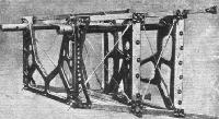
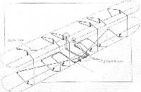
The Fairey IIID Seaplane: Photograph of the tubular framework carrying lower spar attachments and worm-operating gear for flap control.
-
Aviation Historian 40 / J.Kightly, R.Reis - The power of three
Lusitania begins to sink beneath the waves after losing a float on alighting near the rocky outcrop of the St Peter and St Paul Archipelago on April 18. The launch from the Republica is alongside, picking up the airmen and their documents and instruments. Note the Cruz de Cristo retouched on to the underside of the port wing.
-
Aeroplane Monthly 1980-02 / C.Baker - Fixing a Fairey
Регистрационный номер: G-EBKE [9], N9630 [9] Fairey IIID G-EBKE, with broken undercarriage, tied up to the bank of the Potaro.
-
Aeroplane Monthly 1980-02 / C.Baker - Fixing a Fairey
Регистрационный номер: G-EBKE [9], N9630 [9] Left, the IIID supported by river boats immediately after the removal of the chassis. Right, the float chassis detached, leaving the aircraft resting on two bateaus. Note the packing under the mainplane struts, now its sole support.
-
Aeroplane Monthly 1980-02 / C.Baker - Fixing a Fairey
Регистрационный номер: G-EBKE [9], N9630 [9] The IIID supported by a third boat under the centre.
-
Aeroplane Monthly 1980-02 / C.Baker - Fixing a Fairey
Регистрационный номер: G-EBKE [9], N9630 [9] Another view of the IIID with the third boat in position under the fuselage.
-
АвиаМастер 1999-03 / В.Куликов - Славяно-британский авиакорпус на севере России /Белое дело/ (2)
Все, что осталось от гидроплана "Фэйри" IIIC лейтенантов Блампиеда и Харви после вынужденной посадки на лес.
-
Aeroplane Monthly 1979-07 / Painted Wings
Entitled “Fairey Flight”, Michael Turner’s superb formation of Fairey IIIDs of 202 Squadron over Malta.
-
Flight 1920-09 / Flight
The Fairey seaplane: Details of the amphibian gear
-
Flight 1920-09 / Flight
ON THE FAIREY AMPHIBIAN: Two single-acting water rudders are fitted on the outer corners of the float sterns. A rubber cord pulls the rudder inwards
-
Flight 1920-09 / Flight
The tail skid of the Fairey Amphibian is built up of wood laminations
-
Flight 1920-09 / Flight
SOME FAIREY QUICK-RELEASE DEVICES: These are used on the external drag cables to facilitate casting off when folding the wings
-
Flight 1920-09 / Flight
A Fairey inter-plane strut fitting
-
Flight 1921-08 / Flight
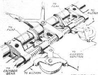
The worm gear operating the wing flaps on the Fairey seaplanes.
-
Flight 1921-08 / Flight
Diagrammatic sketch of Fairey camber gear.
-
Flight 1921-08 / Flight
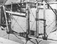
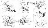
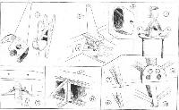
SOME CONSTRUCTIONAL DETAILS OF THE FAIREY TYPE IIID SEAPLANE: (1) The locking device which keeps the wings in place when folded. This fitting is mounted on the lower longeron of the fuselage. (2 and 3) The metal shoes on the ends of the longerons, where they are attached to the steel spool. (4) The spool joint in the top longeron, at the point where the engine unit joins the main fuselage. (5) The very ingenious steel spool at a point where about 14 members meet. (6) The steel spool without the fuselage members. (7) A typical fuselage fitting. (8) Fitting in place.
-
Flight 1921-08 / Flight
SOME WING DETAILS OF THE FAIREY TYPE HID SEAPLANE: (1) Details of the aileron crank, showing how welded joints are not relied upon to transmit stresses. (2) An aileron crank lever in place. (3) Section of a compression strut. The two halves are sprung together, the resulting strut being extremely strong. (4) An interplane strut fitting. The struts are steel tubes with wood fairings. (5) Attachment of built-up compression strut to wing spars. The strut end is located laterally by small wood wedges driven down in corners of U-bolt. (6) Attachment of nose rib to front spar. (7 and 8) Attachment of tubular trailing edge to wing ribs. (9 and 10) Details of the construction of the triangulated ailerons.
-
Мировая Авиация 123
Fairey IIIC
-
Flight 1920-09 / Flight
Fairey III Amphibian
-
Flight 1921-08 / Flight
Fairey Seaplane Type 3D 360 H.P. R.R.Eagle VIII
Тип фотографий
- Все фото (106)
- Боковые проекции (1)
- Цветные фото (5)
- Ч/б фото (80)
- Обломки (6)
- Рисунки, схемы (14)


