Варианты
- Douglas - DC-1 / DC-2 / C-32 / C-39 - 1933 - США
- Nakajima - Ki.34 / L1N - 1936 - Япония
DC-1 / DC-2 / C-32 / C-39
Военно-транспортный самолет. Двухмоторный цельнометаллический моноплан с убирающимся шасси. Военный вариант пассажирского DC-2, созданного в КБ "Дуглас эйркрафт" под руководством Дж. Кинделбергера и Э. Рэймонда. В свою очередь, конструкция DC-2 опиралась на опытный самолет DC-1. Головной серийный (опытного образца не было) DC-2 взлетел 11 мая 1934 г. Образец первого настоящего военно-транспортного варианта, XC-32 на базе DC-2-153, поднялся в воздух в 1935 г. В апреле 1936 г. начался серийный выпуск самолетов C-33 и C-34. Их строил завод "Дуглас" в Санта-Монике. Всего изготовили 193 DC-2, в т.ч. 58 машин военных вариантов.
Экипаж - 3 чел., 12 пассажиров. Моторы R-1820. Штатного вооружения не было, но существовали полевые переделки 1 - 3x7,69 (7,9). Самолеты семейства C-32/C-39 эксплуатировались в США (флотом - с середины 1934 г., ВВС армии - с апреля 1936 г.) и Австралии (с января 1942 г.). Гражданские DC-2 использовались военной авиацией Великобритании (с апреля 1941 г. - DC-2K), Австралии (с ноября 1940 г.), Финляндии (с января 1940 г.).
Существовали следующие военные варианты DC-2:
- R2D-1, гражданские самолеты модификации DC-2-125 с моторами R-1820-10 и небольшими изменениями по оборудованию для Корпуса морской пехоты США;
- C-33 с моторами R-1820-33, грузовой дверью и увеличенным вертикальным оперением, груз до 1100 кг;
- C-34, салонный вариант C-33 с моторами R-1820-25;
- C-39 (DC-2-243) с моторами R-1820-55 и оперением от DC-3, груз до 1630 кг;
- C-32A с моторами R-1820-33, гражданские машины, реквизированные в 1942 г. с немного упрощенным интерьером салона.
R2D-1 использовались для обучения морских пехотинцев прыжкам с парашютом с середины 1934 г.
C-33 эксплуатировались как транспортные. Первое боевое применение DC-2 - франкистами во время гражданской войны в Испании в августе 1936 г. Они превратили их в бомбардировщики. Аналогично поступили и финны в начале 1940 г. Их единственный DC-2 бомбил по ночам советские войска на Карельском перешейке.
C-33 и C-39 до войны составляли основу американской военно-транспортной авиации. Они приняли участие в эвакуации американских войск с Филиппин в декабре 1941 г. Весной следующего года эти машины осуществляли перевозки на передовую на Новой Гвинее (в т. ч. со сбросом грузов на парашютах). Позднее эксплуатировались в основном в тыловых районах.
Англичане купили партию DC-2K в 1941г. В апреле они уже перебрасывали свои войска в Иран. В мае DC-2K появились в Египте: доставляли грузы на передовую, вывозили раненых. В декабре они также спешно перевезли из Индии подкрепления в Бирму.
Австралийцы в ноябре 1940 г. реквизировали гражданские DC-2. Весной 1942г. они вместе с предоставленными США C-39 обеспечивали с воздуха всем необходимым войска, воевавшие в джунглях Новой Гвинеи.
Производство C-39 прекратили в сентябре 1939 г. В Австралии DC-2 в январе 1943 г. передали в учебные подразделения, а списали в 1945 г. В США последние C-39 летали до 1946 г. Дольше всех просуществовали DC-2 в ВВС Финляндии - их сняли с вооружения в 1955 г.
C-39||
Размах:||25,91 м
Длина:||18,75 м
Моторы, количество х мощность:||2x975 л.с.
Взлетная масса, максимальная:||9526 кг
Максимальная скорость:||338 км/ч
Практический потолок:||6280 м
Дальность:||1885 км
Описание:
- DC-1 / DC-2 / C-32 / C-39
- Douglas DC-1 и DC-2
- Flight, March 1934
THE DOUGLAS D.C.1 - Flight, October 1934
THE SUCCESSFUL MACHINES - Flight, November 1934
EFFICIENCY
Фотографии
-
Авиация и Космонавтика 2013-10 / В.Морозов - Великая воздушная гонка
Регистрационный номер: PH-AJU [24] Дуглас DC-2
-
Мировая Авиация 114
Регистрационный номер: EC-AGA Первоначально приобретенный для перевозки австрийского канцлера Дольфуса, самолет с регистрационным номером EC-AAA был затем продан компании "Lineas Aereas Postales Espanolas" (LAPE). Номер EC-AGA он получил в 1936 году. В годы испанской гражданской войны его эксплуатировали республиканцы.
-
Air International 2002-06 / R.Whitford - Fundamentals of Airliner Design /Commercial/ (9)
Регистрационный номер: PH-AJU [24], NC39165 [14] Douglas chose the Wright F3 model of the R-1820 Cyclone for use in its new airliner, the DC-2. The Cyclone was Wright's first really successful air-cooled high power engine and its reliability gave passengers confidence in the twin-engine (rather than tri-motor) configuration.
-
Авиация и Космонавтика 2013-10 / В.Морозов - Великая воздушная гонка
Регистрационный номер: PH-AJU [24], NC39165 [14] Эпизод съемок фильма об "Уивер". Рядом с самолетом собираются раритетные автомобили
-
Aeroplane Monthly 1999-10 / M.Oakey, T.Harmsworth - News
Регистрационный номер: PH-AJU [24], NC39165 [14] DC-2 NC39165 over the North Sea on its way from Bruntingthorpe to Amsterdam on August 15, 1999.
-
Авиация и Космонавтика 2013-10 / В.Морозов - Великая воздушная гонка
Регистрационный номер: PH-AJU [24], NC39165 [14] Отреставрированный DC-2 снова в воздухе, 1983 г.
-
Aeroplane Monthly 1984-04 / Douglas R2D-1/DC-2 NC39165 /Preservation Profile/
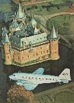
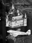
Регистрационный номер: PH-AJU [24], NC39165 [14] NC39165 above Haarzuilens Castle near Utrecht in the Netherlands. Photograph provided by KLM.
-
Aeroplane Monthly 1989-07
Регистрационный номер: NC1934D MICHAEL O'LEARY'S impressive centre-spread features the magnificent Douglas DC-2 recently restored by the Douglas Historical Foundation. It is seen in flight near Catalina Island in April this year.
-
Flight 1935-07 / Flight
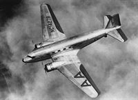
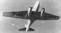
Регистрационный номер: NC14278 [3] Looking down on a Douglas: This machine, perhaps more than any other, has given the American flying passenger a new conception of air travel
-
Aeroplane Monthly 2001-05 / H.Friedman, A.Friedman - The Legacy of the Rockne Crash /Accident analysis/
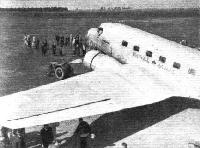
Регистрационный номер: NC14278 [3] Following on from the DC-1 was the DC-2 - the immediate predecessor of the world's most famous transport, the DC-3 - shown here in American Airlines colours.
-
Мировая Авиация 11
Регистрационный номер: NC14278 [3] Здесь хорошо показаны характерные обводы крыла DC-2. Фирменная раскраска "American Airlines" включает черную окраску элеронов сверху, что еще больше подчеркивает форму крыла.
-
Flight 1936-10 / Flight
Регистрационный номер: X223Y [8], NC223Y [8] LINER-YACHT. Howard Hughes, the American film producer and aviation enthusiast, has acquired this Douglas D.C.1 with a pair of Wright Cyclones as a racing and experimental machine. Hughes refused to enter it for the recent Bendix Trophy transcontinental race, insisting that he is strictly an amateur pilot. As an American contemporary so aptly puts it, the machine would have been a "near-cinch." Someone else remarked, "You can't beat 120 million dollars."
-
Flight 1933-12 / Flight
The Douglas "Airliner" with latest N.A.C.A. cowling for "Cyclone" geared and supercharged engines.
-
Flight 1934-02 / Flight
A front view of the new Douglas DC.1 "Transport," a twin-engined (Wright "Cyclone" or Pratt & Whitney "Hornet") 14-18-seater low-wing monoplane with retractable undercarriage.
-
Flight 1936-02 / Flight
When accurate navigation is necessary: A sea of cloud laps against the Alps; Basle lies below it.
-
Мировая Авиация 122
Регистрационный номер: X223Y [8], NC223Y [8] Так и оставшийся в единственном экземпляре, DC-1 поднялся в воздух в июле 1933 года, затем использовался для испытаний и в качестве демонстрационного, а в гражданскую войну в Испании стал разведчиком и транспортным самолетом в республиканских ВВС.
Blueprint for the future - the sole Douglas DC-1 made its maiden flight on July 1, 1933. The aircraft was never issued with an Approved Type Certificate (ATC) but instead operated under Memo Certificate 2-460 conditions, which allowed it to carry paying passengers as NC223Y or undertake experimental work as X223Y. -
Мировая Авиация 9
Регистрационный номер: NC223Y [8], X223Y [8] 1 июля 1933г.: первый полет на аэродроме Кловер-филд, Санта-Моника, выполнил первый гражданский авиалайнер фирмы "Douglas" - DC-1.
-
Авиация и Космонавтика 2013-07 / Знаменательные даты III квартала 2013г. в области авиации
Регистрационный номер: X223Y [8], NC223Y [8] -
Aviation Historian 12 / E.Young - Over the Weather
The DC-1, displaying its record-setter status, is prepared for another research flight
-
Авиация и Космонавтика 2018-07 / Некоторые знаменательные даты июля в истории авиации
Регистрационный номер: NC223Y [8], X223Y [8] -
Flight 1934-03 / Flight
Регистрационный номер: X223Y [8], NC223Y [8] Был построен только один DC-1, и фирма "Douglas" потеряла 306 778 долларов собственных средств на создание и испытания этого самолета. Тем не менее, он расчистил путь для самолетов мирового класса DC-2 и DC-3.
A Douglas D.C.1 "Transport" as supplied to Transcontinental & Western Air, Inc. -
Aeroplane Monthly 2001-05 / H.Friedman, A.Friedman - The Legacy of the Rockne Crash /Accident analysis/
Регистрационный номер: X223Y [8], NC223Y [8] Blighted by the Rockne crash, trimotor airliners in general fell from favour in the USA. Famously, the beneficiary of the tragedy was the Douglas Aircraft Company, which produced the first of an immortal line of airliners. This is the prototype and only Douglas DC-1; the photograph is dated July 1, 1933.
-
Авиация и Космонавтика 2013-11 / ??? - Самолету Ли-2 - 75 лет
Регистрационный номер: X223Y [8], NC223Y [8] Прототип самолета, имевший обозначение DC-1, был построен в одном экземпляре и совершил первый полет 80 лет тому назад, 1 июля 1933 г.
-
Aviation Historian 12 / E.Young - Over the Weather
The goal - TWA’s Jack Frye was determined to provide the best possible service, both in terms of passenger experience and economic viability.
-
Aviation Historian 1 / M.O'Leary - The tragedy of Flight Three
A pre-war line-up of TWA hardware at Burbank, California. Nearest the camera is a Douglas DC-3, beyond which is a DST with a DC-2 behind it. All sport the legend “The Lindbergh Line”, the famous aviator having joined one of TWA’s predecessors, Transcontinental Air Transport, in 1928.
Другие самолёты на фотографии: Douglas DC-3 / C-47 Skytrain/С-53 Skytrooper / Dakota - США - 1935
-
Flight 1933-12 / Flight
The Douglas "Airliner" with latest N.A.C.A. cowling for "Cyclone" geared and supercharged engines.
-
Flight 1935-07 / Flight
Unloading the forward mail compartment of the Douglas
-
Air International 1987-03 / R.Braybrook - The Sixties, the Thirties and the American Challenge
Регистрационный номер: NC14275 Continuing to demonstrate its world lead in the design of economically superior airliners, the US industry produced such types as the Boeing 247D and Douglas DC-2 (shown).
-
Aeroplane Monthly 1978-04
Регистрационный номер: NC39165 [14], PH-AJU [24] Colgate Darden's Douglas DC-2, the last airworthy example of the breed, photographed by CHRIS SORENSEN in 1976.
-
Моделист-Конструктор Военно-транспортные самолеты Второй мировой войны
C-39 в полете вблизи Сакраменто (Калифорния), сентябрь 1939 г.
-
Мировая Авиация 122
"China National Airways Corporation" эксплуатировала несколько DC-2 перед Второй мировой войной и в течение нее: часть из них ранее принадлежала "Pan American", а два DC-2 купили напрямую у "Douglas".
-
Aviation Historian 31 / T.Culbert - The Hump pioneers
One of at least eight DC-2s operated by CNAC being refuelled in typically primitive conditions.
-
Мировая Авиация 122
Регистрационный номер: NC14274 Успешный опыт эксплуатации DC-2 в TWA побудил другие компании также приобрести самолет. Среди них оказалась и "American Airlines", купившая 16 авиалайнеров DC-2-120.
-
Мировая Авиация 122
Регистрационный номер: J-BBOQ "Nakajima" приобрела один DC-2 и один машино-комплект, а в 1936-1937 годах собрала еще пять для "Dai Nippon Koku KK", эксплуатировавшей их между Японией и Формозой (Тайванем).
-
Air Pictorial 1959-09
Dennis M. Powell of Kenya sent us this rare photograph of a Pegasus-engined Douglas DC-2.
-
Flight 1935-01 / Flight
The Douglas at Gravesend. Below the machine can be seen Mr. Anthony Fokker, Mr. H. Gooding (the Gravesend manager), Mr. Parmentier and Mr. Prins.
-
Flight 1935-09 / Flight
WHAT POLAND WANTED. Bristol Pegasus III moderately supercharged radials rated at 690 h.p have been installed in a pair of Douglas D.C.2's for the Polskie Linje Lotnicze, "Lot," one of which is shown here.
-
Flight 1938-11 / Flight Advertisements
THE DOUGLAS DC2 (2 “Bristol” Pegasus) as supplied to Polskie Linje Lotnicze “LOT,” the Polish airline company. The DC2 is a twin-engined low-wing cantilever monoplane of cellular multi-web construction in aluminium alloy; with trailing-edge flaps, retractable undercarriages and wheel brakes. Normal passenger accommodation is 14, and provision is made for ventilation and steam-heating, buffet with refrigerator, etc. Two cargo and mail compartments. Span 85 ft., length 62 ft., height 16 ft. 3 in., useful load 6,152 lbs. Speed 198 m.p.h. at 6,500 feet. Built by Douglas Aircraft Co., Inc., U.S.A.
-
Flight 1935-08 / Flight
Filling up the new K.N.I.L.M. Douglas with Shell 87-octane fuel.
-
Flight 1935-08 / Flight
A Douglas D.C.2 recently delivered to K.N.I.L.M. being assembled at the Dutch naval aerodrome at Surabaya
-
Flight 1934-10 / Flight
The Douglas D.C.2 (two Wright "Cyclones") piloted by Parmentier and Moll.
-
Flight 1934-09 / Flight
SPEED: The Douglas D.2 has a top speed of over 200 m.p.h., and cruises at about 193 m.p.h., while carrying 14 passengers.
-
Авиация и Космонавтика 2013-10 / В.Морозов - Великая воздушная гонка
Регистрационный номер: PH-AJU [24] DC-2 "Уивер" авиакомпании "KLM" стартует с Амстердама". Стартового номера на киле еще нет
-
Авиация и Космонавтика 2013-10 / В.Морозов - Великая воздушная гонка
Регистрационный номер: PH-AJU [24] Дозаправка DC-2 на промежуточном аэродроме
-
Flight 1934-11 / Flight
Регистрационный номер: PH-AJU [24] -
Flight 1934-10 / Flight
Регистрационный номер: PH-AJU [24] A NETHERLANDS PAIR: The big Douglas DC.2 (two Wright "Cyclone" Fs) flown - with three fare-paying passengers - by K. D. Parmentier and J. J.Moll, and, behind is the Panderjager.
Другие самолёты на фотографии: Pander S-4 Postjager - Нидерланды - 1933
-
Авиация и Космонавтика 2013-10 / В.Морозов - Великая воздушная гонка
Регистрационный номер: PH-AJU [24] Голландский DC-2 накануне гонки в Милденхолле
-
Flight 1934-12 / Flight
Регистрационный номер: PH-AJU [24] RECEPTION: When the K.L.M. "Douglas" returned to Schipol aerodrome, Amsterdam, after the Melbourne Race, 80,000 people were present to see the famous machine and its crew. The line of mounted police in the background adds a picturesque touch.
-
Мировая Авиация 122
Регистрационный номер: PH-AJU [24] Первым экспортным заказчиком DC-2 стала голландская KLM, использовавшая такие машины на большинстве своих маршрутов. Самолет PH-AJU стал вторым в гонках на кубок Мак-Робертсона.
-
Мировая Авиация 11
Регистрационный номер: PH-AJU [24], NC39165 [14] DC-2 предстал перед широкой общественностью в Европе, когда первый самолет KLM выиграл этап с гандикапом авиационной гонки MacRobertson Air Race. На фотографии: воссоздание событий, 1984 год.
-
Авиация и Космонавтика 2013-10 / В.Морозов - Великая воздушная гонка
Регистрационный номер: PH-AJU [24] Жители Олбери вытягивают DC-2 из грязи на взлетную полосу
-
Aeroplane Monthly 1984-02 / P.Jarrett - Grapevine
Регистрационный номер: PH-AJU [24], NC39165 [14] Late in November, the DC-2 loaned to KLM to masquerade as PH-AJU Uiver for the MacRobertson Race commemorative flight from Mildenhall to Australia, paid a brief visit to Duxford for filming. The aircraft, NC39165, is to star in a Netherlands Broadcasting Corporation three-part documentary about the race, due to be broadcast next October to coincide with the 50th anniversary of the MacRobertson Race and KLM’s 65th birthday.
-
Aeroplane Monthly 1976-03 / Personal album
Регистрационный номер: PH-AKS [2] In 1936 a terminal was built at the Doncaster Municipal Airport with facilities to check-in up to 12 passengers at a time. KLM was a regular user of the airport, their DC-2s, mainstay of the European fleet, being regular visitors. Photograph shows Douglas DC-2 PH-AKS Sperwer coming into Doncaster some time in 1938. Note the Doncaster Race course in the background.
-
Flight 1937-02 / Flight
A K.L.M. Douglas D.C.2.
-
Aeroplane Monthly 1984-04 / Douglas R2D-1/DC-2 NC39165 /Preservation Profile/
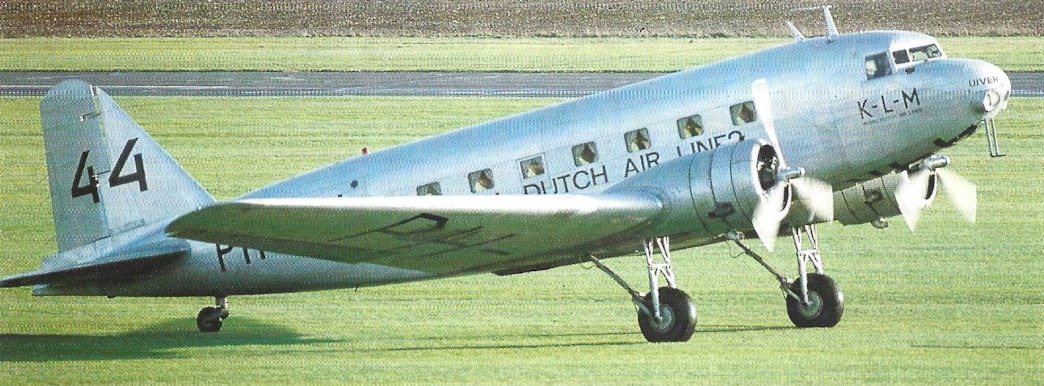
Регистрационный номер: PH-AJU [24], NC39165 [14] NC39165 airborne in KLM markings as PH-AJU Uiver.
-
Aeroplane Monthly 1983-12 / P.Jarrett - Grapevine
Регистрационный номер: PH-AJU [24], NC39165 [14] A veteran airworthy Douglas DC-2 has been purchased by KLM, and is to refly the route of the October 1934 MacRobertson England-Australia air race to mark the 50th anniversary of the event. Bought from American Colgate Darden, the DC-2, NC39165, went by container ship to Antwerp, Belgium, and reached Schiphol airport by canal on September 4, 1983.
-
Aeroplane Monthly 1984-04 / Douglas R2D-1/DC-2 NC39165 /Preservation Profile/
Регистрационный номер: PH-AJU [24], NC39165 [14] NC39165 enroute for Schiphol last summer
-
Мировая Авиация 18
Регистрационный номер: PH-AJU [24] 24 октября 1934г.: самолет DC-2 авиакомпании KLM, вылетевший из Милденхелла (Саффолк) 20 октября, прибыл в Мельбурн (Австралия) вторым и занял первое место в классе транспортных самолетов в гонке на кубок Мак-робертсона. Перелет занял 90 часов 17 минут.
-
Air Pictorial 1999-10
Регистрационный номер: PH-AJU [24], NC39165 [14] Douglas DC-2 at Bruntingthorpe on August 4, 1999, preparing to depart for Amsterdam for display in the Aviadome. It carries KLM colours as Uiver, the 1934 Mildenhall Air Race contestant.
-
Aeroplane Monthly 1984-02 / P.Jarrett - Grapevine
Регистрационный номер: PH-AJU [24], NC39165 [14] Late in November, the DC-2 loaned to KLM to masquerade as PH-AJU Uiver for the MacRobertson Race commemorative flight from Mildenhall to Australia, paid a brief visit to Duxford for filming. The aircraft, NC39165, is to star in a Netherlands Broadcasting Corporation three-part documentary about the race, due to be broadcast next October to coincide with the 50th anniversary of the MacRobertson Race and KLM’s 65th birthday.
-
Aviation Historian 8 / R.Mulder - Capital Gains: Oslo-Fornebu airport 1934-40
KLM Douglas DC-2 PH-AKI at Fornebu Airport, 1939;
-
Flight 1934-10 / Flight
IMPRESSIVE: An ant's-eye view of the K.L.M.'s big Doug!as.
-
Aeroplane Monthly 1980-02 / Gravesend /Gone but not forgotten/ (7)
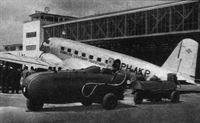
Регистрационный номер: PH-FOK The spuriously-registered DC-2 PH-FOK at Gravesend on January 19, 1935.
-
Aviation Historian 41 / D.Stringer - Around the world in 28 days!
Регистрационный номер: PH-ALF [2] Dutch national airline KLM was an early adopter of the ultra-modern Douglas DC-2, placing an order for 14 in late 1934. Our global traveller would probably have flown in a DC-2 on the Milan/London - Frankfurt leg; perhaps even in this one, PH-ALF (c/n 1585), named Flamingo, although it wouldn’t have been on the service for much longer - it crashed near Brussels on July 28, 1937.
-
Aviation Historian 24 / R.Pegram - Imperial Airways. The 1930s: a cause for concern?
Регистрационный номер: PH-ALF [2] The Douglas DC-2 represented the state of the art when it was introduced into European service by Dutch national airline KLM in the summer of 1934. The sleek 14-passenger monoplane had made its first flight on May 11 that year, the same month that Imperial put the Short Scylla biplane into service on its European routes.
-
Flight 1938-02 / Flight
Past and Future: A striking impression of the Stearman Hammond and one of K.L.M.’s D.C.2s on the tarmac at Croydon. The Hammond is, of course, being used to accustom the company’s pilots to the tricycle technique in preparation for possible operation of Douglas D.C.4s in due course. The Hammond is, however, primarily interesting as a private type - or as the basis of future private types.
Другие самолёты на фотографии: Stearman-Hammond Y-1 - США - 1936
-
Flight 1938-10 / Flight
Регистрационный номер: PH-AKP [2] SUMMER AT SCHIPHOL: A glimpse from the windows of the restaurant and waiting room at Amsterdam's airport. At times there are as many as half a dozen Douglases lined up on the apron.
-
Aeroplane Monthly 1985-03 / J.Stroud - Wings of Peace
Регистрационный номер: PH-AKS [2] The first arrivals at Bromma Airport, Stockholm, when it opened in May 1936 were ABA’s F.XXII Lappland and KLM’s Douglas DC-2 PH-AKS Sperwer (Sparrowhawk).
Другие самолёты на фотографии: Fokker F.XXXVI / F.XXII - Нидерланды - 1934
-
Aeroplane Monthly 1989-02 / Skywriters
Регистрационный номер: PH-ALD In the foreground is Gladiator K7960, in the background a D.H.86, DC-2, D.H.84 Dragon, DC-3 and an S.73, all diverted to Kenley because of bad weather.
Другие самолёты на фотографии: De Havilland Dragon / D.H.84 - Великобритания - 1932De Havilland Express Air Liner / D.H.86 - Великобритания - 1934Douglas DC-3 / C-47 Skytrain/С-53 Skytrooper / Dakota - США - 1935Gloster Gladiator - Великобритания - 1934Savoia-Marchetti / SIAI S.73 - Италия - 1934
-
Flight 1938-04 / Flight
Регистрационный номер: PH-AKT London’s Terminal : British Airways, imperial Airways and K.L.M. on the tarmac at Croydon.
Другие самолёты на фотографии: Lockheed Electra 10 - США - 1934Short Scylla / L.17 - Великобритания - 1934
-
Flight 1938-02 / Flight
Регистрационный номер: PH-AKJ A photograph of the general maintenance shops, one of many devoted to different items of equipment. The machine on the left of the picture will be recognised as one of the D.C.3s used by K.L.M. on their Batavia service
Другие самолёты на фотографии: Douglas DC-3 / C-47 Skytrain/С-53 Skytrooper / Dakota - США - 1935
-
Flight 1939-11 / Flight
TEMPORARILY IMMOBILISED: Douglas DC.3s and DC.2s of the K.L.M. in a hangar “somewhere in Holland.” It is hoped that most of these machines will soon be able once more to go about on their lawful occasions.
Другие самолёты на фотографии: Douglas DC-3 / C-47 Skytrain/С-53 Skytrooper / Dakota - США - 1935
-
Flight 1939-02 / Flight
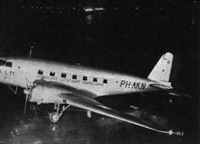
Регистрационный номер: PH-AKN -
Aeroplane Monthly 1990-09 / Personal album. Civil
Регистрационный номер: PH-AKK KLM's Douglas DC-2 PH-AKK Koetilang. The type was KLM’s first all-metal airliner and in 1934 was the first aircraft to introduce stewardesses. KLM was also the first European airline to operate the DC-2, and later became the first to put the DC-3 into European service. Introduced into KLM service in April 1935, PH-AKK was destroyed by bombing at Schiphol airport on May 5, 1940.
-
Aeroplane Monthly 1976-03 / Personal album
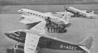
Регистрационный номер: PH-AKH This view of Croydon in 1938 shows British Airways' D.H.86A G-ADEC nearest the camera. This aircraft began life in 1935 with Hillmans Airways, and was absorbed into British Airways the following year. Shortly after this photograph was taken 'EC was sold to Uruguay as CX-AAH. The centre aircraft of the group is KLM's DC-2 PH-AKH, Haan, with Air France's three engined Wibault Penhoet F-AMHM in the background.
Другие самолёты на фотографии: De Havilland Express Air Liner / D.H.86 - Великобритания - 1934Wibault Wibault 280 - Франция - 1930
-
Мировая Авиация 11
DC-3 (на переднем плане) и DC-2 принадлежат компании KLM - первой компании за пределами США, эксплуатирующей DC-3.
Другие самолёты на фотографии: Douglas DC-3 / C-47 Skytrain/С-53 Skytrooper / Dakota - США - 1935
-
Flight 1938-11 / Flight Advertisements
Регистрационный номер: PH-AKP [2] -
Aviation Historian 8 / R.Mulder - Capital Gains: Oslo-Fornebu airport 1934-40
Регистрационный номер: PH-AKI [2], D-ADBK [2] KLM Douglas DC-2 PH-AKI Kievit (c/n 1355) is the subject of great interest before its departure from Fornebu for Kristiansand and Amsterdam on June 1. This aircraft was taken over by German forces in May 1940, after which it was given the German civil registration D-ADBK and later served with the Luftwaffe as NA+LD.
-
Aviation Historian 8 / R.Mulder - Capital Gains: Oslo-Fornebu airport 1934-40
Регистрационный номер: PH-AKI [2], D-ADBK [2] Passengers disembark from a coach beside the restaurant rotunda and make their way towards DC-2 PH-AKI for the flight to Amsterdam on June 1. Thankfully the weather on the opening day was excellent and no flights were delayed.
-
Flight 1935-05 / Flight
A section of the long line of machines on exhibition. In the foreground is the B.A.C. "Drone," then a Spartan "Cruiser," a Railway Air Services D.H.86, the K.L.M. Douglas D.C.2, and others.
Другие самолёты на фотографии: De Havilland Express Air Liner / D.H.86 - Великобритания - 1934Kronfeld Drone - Великобритания - 1932Spartan Cruiser - Великобритания - 1932
-
Aeroplane Monthly 1985-02 / J.Stroud - Wings of Peace
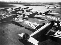
A typical prewar scene at Berlin's Tempelhof Airport. This picture taken in 1934 includes 11 Lufthansa Ju 52/3ms in the foreground, KLM and LOT Douglas DC-2s beyond and, further away, another Ju 52/3m.
Другие самолёты на фотографии: Junkers Ju.52/3m - Германия - 1931
-
Авиация и Космонавтика 2024-09 / В.Морозов - Военная авиация Польши 1918-2024гг. (3)
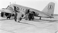
Регистрационный номер: SP-ASL Один из двух DC-2 авиакомпании «LOT». Фото 1938-1939 гг.
-
Aeroplane Monthly 1977-01 / G.Endres - Czechoslovakian Air Transport since 1920 (1)
Регистрационный номер: OK-AIC The apron at Prague Ruzyne airport in 1938, with three DC-2s, a Fokker FVIIb-3m, an Avia F.39, a Wibault 283.T and a Potez 62 in evidence.
Другие самолёты на фотографии: Fokker F.IX / F.XII / F.XVIII - Нидерланды - 1929Fokker F.VII / C-2 / F.XIV - Нидерланды - 1924Potez Potez 62 / 65 - Франция - 1935Wibault Wibault 280 - Франция - 1930
-
Aviation Historian 34 / M.Wickstead - Czechoslovakia's "Carefully Serving Airline"
Регистрационный номер: OK-AIB Douglas DC-2 OK-AIB was one of five operated by CLS, along with four DC-3s, all of which were used on scheduled international services until Germany’s occupation of Czechoslovakia in 1938, when both CSA and CLS were forced to cease operations. The CLS fleet of Douglas transports was transferred to Deutsche Luft Hansa, none seeing service in Czechoslovakia after the war.
-
Aviation Historian 34 / M.Wickstead - Czechoslovakia's "Carefully Serving Airline"
Регистрационный номер: OK-AIA CLS acquired its fleet of Douglas DC-2s - including OK-AIA, seen here at Prague circa 1936 - and DC-3s via Fokker before the war.
-
Flight 1936-08 / Flight
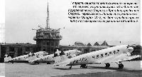
Регистрационный номер: HB-ITA [2], HB-ITE [2], HB-ITO [3], F-BJHR [3], ZS-DFW [2], ZS-DFX [3] 1 апреля 1935г.: авиакомпания "Swissair" открывает первый регулярный рейс в Соединенное Королевство из Цюриха в Кройдон, графство Сюррей, через Базель. Линию обслуживали самолеты Douglas DC-2, на фотографии три из
них у пассажирского терминала в Кройдоне.
THE HOLIDAY RUSH: An unusual sight at Croydon on a recent Saturday, when the Swissair Douglases carried a record amount of traffic between London and Switzerland. -
Flight 1936-02 / Flight
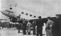
The Douglas on the tarmac in front of the terminal building at Zurich - an example of clean and "obstruction-free" design which might be copied elsewhere.
-
Flight 1936-02 / Flight
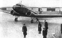
Waiting for permission to leave the tarmac at Croydon. The loop aerial can be seen above the control cabin as well as the oiled leather-coated spinners for ice protection.
-
Flight 1935-03 / Flight
One of Swissair's new Douglas machines at Zurich.
-
Flight 1935-03 / Flight
DEMONSTRATION: One of the two Swissair Douglas machines, which were demonstrated recently at Croydon, being refuelled beside the Imperial Heracles. Actually, the "Scylla" class will probably be used, as last year, for our own part of the Zurich service. The Government has offered a prize of ?25,000 to encourage the production of medium-sized commercial machines.
Другие самолёты на фотографии: Handley Page H.P.42 / H.P.45 - Великобритания - 1930
-
Flight 1940-04 / Flight
SPRING SEES A REVIVAL OF COMMERCIAL FLYING, BUT NOT IN THIS COUNTRY. Before the start of the first Swissair Douglas on the inaugural flight of the new Locarno-Rome route.
-
Flight 1938-02 / Flight
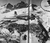
Регистрационный номер: HB-ITA [2] ST. MORITZ STUDY. A fine impression of a Swissair Douglas D.C.2 taking off from the new “fine-weather” airport at Samaden {5,500 ft. above sea level), which is proving so useful to winter sports visitors to St. Moritz.
-
Flight 1938-03 / Flight
Регистрационный номер: HB-ISI Winter sports enthusiasts can now reach the St. Moritz playgrounds by means of Swissair’s new "on demand" fine-weather service from London to Samaden, the 5,000 ft. aerodrome adjoining the famous resort. This fine photograph shows the Douglas D.C.2 amid some of the most striking scenery of the Engadine
-
Flight 1938-03 / Flight
A view of St. Moritz itself, taken by a member of the staff of Flight from the D.C.2 as it circled the town.
-
Flight 1938-02 / Flight
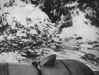
The photograph of the Oberland south of Glarus gives a good impression of the type of scenery which is enjoyed by the Alpine air traveller.
-
Flight 1936-12 / Flight
CHRISTMAS RUSH: A tarmac impression at Croydon on December 24. Beneath the port wing of the Swissair Douglas can be seen an Air France Wibault, an H.P. 42, Scylla and Syrinx, while behind the Douglas is a Railway Air Services' D.H.86.
Другие самолёты на фотографии: De Havilland Express Air Liner / D.H.86 - Великобритания - 1934Handley Page H.P.42 / H.P.45 - Великобритания - 1930Short Scylla / L.17 - Великобритания - 1934Wibault Wibault 280 - Франция - 1930
-
Aviation Historian 31 / T.Culbert - The Hump pioneers
Регистрационный номер: DG471, VT-AOS Douglas DC-2 DG471/VT-AOS (c/n 1244) was one of 12 impressed into RAF service with No 31 Sqn in February 1941. It never made it to Dinjan, crashing at Karachi in October 1941.
-
Aviation Historian 16 / K.Honey - In the Land of Black Gold
Регистрационный номер: ZS-DFX [3], F-BJHR [3], HB-ITO [3] Douglas DC-2 ZS-DFX originally joined Swissair as HB-ITO in February 1935, serving with the airline until it was sold to South African operator Phoenix Airlines in the summer of 1952. It was then acquired by the Astra Aircraft Corporation and operated by the Basutoland Railway Administration, before joining Silver City’s Libyan fleet in 1957.
-
Aviation Historian 24 / N.Stroud - Vikings in Africa /The John Stroud Archive/
Регистрационный номер: ZS-DFW [2], HB-ITE [2] Formerly HB-ITE in Swissair service, Douglas DC-2 ZS-DFW (c/n 1322) was photographed by John at Entebbe, where the 1934-vintage airliner was plying its trade for Phoenix Airlines. It may be one of the last photographs of the machine, as it was destroyed in a landing accident at Kosti, south of Khartoum, two months later.
-
Flight 1935-07 / Flight
The Douglas D.C.2 at Mangua, the capital of Nicaragua
-
Flight 1936-06 / Flight
FOR THE BASS STRAIT SERVICE: Holyman's Airways take delivery of their new Douglas D.C.2 after erection at Essendon (Melbourne). For the moment it is flying between Melbourne and Sydney, but it will eventually be put on the Melbourne-Launceston service.
-
Aeroplane Monthly 1984-04 / Douglas R2D-1/DC-2 NC39165 /Preservation Profile/
Регистрационный номер: NC39165 [14], PH-AJU [24] N39165 during its post-war civil career
-
Aeroplane Monthly 2000-02 / J.Golley - A Clandestine Assignment /Secret ferry flights/
Регистрационный номер: DG469 As well as Lodestars, Stuart Hall and his fellow officers ferried Douglas DC-2s across the Atlantic. Here DC-2 DG469 of 31 Sqn is seen at Beersheba, Hebron, Israel. Aircraft in the background include (on the left) Hawker Audax K7514.
Другие самолёты на фотографии: Hawker Audax - Великобритания - 1931
-
Aviation Historian 31 / T.Culbert - The Hump pioneers
Регистрационный номер: AX767, G-AGCI Delivered into RAF hands by PAA-Africa pilots as “U.S.8” in September 1941, former TWA and Braniff DC-2 AX767/“N” (also formerly G-AGCI in BOAC service) operated with No 31 Sqn in India during April-May 1942. The unit received Battle Honours for its air transport work in Burma during 1941-42.
-
Jane's All the World Aircraft 1938 / 03 - All the world's aeroplanes
A Douglas DC-2 Monoplane as used by the U.S. Army Air Corps for transport duties.
-
Моделист-Конструктор Военно-транспортные самолеты Второй мировой войны
C-33 из 83-й транспортной группы на маневрах в 1941 г.: выгрузка противотанковых пушек
-
Мировая Авиация 122
Республиканцы имели в начале гражданской войны четыре DC-2, но данный самолет был захвачен националистами и использовался генералом Франко в качестве личного транспортного самолета.
-
Air Enthusiast 1999-03 / J.Serrano - Fifty years of DC service
Регистрационный номер: EC-AAC DC-2 EC-AAC ‘Vara de Rey’, formerly 42-1, in pre-Iberia markings at Madrid’s Barajas Airport in the immediate Spanish postwar period.
-
Мировая Авиация 122
Служба в ВС США. Американские военные заказали несколько DC-2: пять с двигателями Wright мощностью 710 л. с. для ВМС США (под обозначением R2D-1 использовались как штабные транспортные), а 18 машин приобрел авиакорпус Армии США под обозначением C-33, они эксплуатировались в качестве транспортных (отличались увеличенными килем и рулями, имели грузовую дверь на левом борту). Кроме того, 24 бывших гражданских DC-2 поступили в авиакорпус Армии США как C-32A, военные получили два персональных транспортных YC-34, а из прототипа C-38 получился "DC-2 1.2" - некая комбинация DC-2 и DC-3. Один C-38 оснащался двумя Wright R-1820-45 мощностью по 975 л. е., имел хвостовую часть по типу DC-3 и стал основой для разработки и постройки 39 самолетов C-39, соединивших в себе фюзеляж C-33 и центроплан, хвостовую часть и шасси от DC-3. Два схожих самолета - C-41 с двигателями Pratt & Whitney R-1820-21 мощностью по 1200л.с.и C-42 с Wright R-1820-53 мощностью по 1000 л. с. - использовались генералом Генри X. Арнольдом, командующим авиакорпусом Армии США, и позже командным составом ВВС Армии США.
-
Air Pictorial 1957-03 / Air Pictorial's photo-review
Регистрационный номер: DO-1 A venerable Douglas DC-2 transport of the Finnish Air Force (serial DO-1; DO-2 is DC-3)
-
Моделист-Конструктор Военно-транспортные самолеты Второй мировой войны
Этот DC-2 зимой 1939/40 г. использовался финскими летчиками как ночной бомбардировщик
-
Aeroplane Monthly 1983-03 / P.Jarrett - Grapevine
Регистрационный номер: NC13733 At Douglas Long Beach one of five surviving DC-2s, NC13733, is being restored to airworthiness by spare-time employees and retirees. The aim is to fly her in time for the 50th anniversary of the DC-2’s first flight on May 11, 1934.
-
Flight 1934-11 / Flight
The split trailing edge flaps, and the arrangement of the retractile undercarriage. Note the generous fillet at the junction of wing and fuselage.
-
Flight 1936-02 / Flight
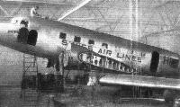
Overhauling one of the five Swissair Douglas machines in the Zurich shops, which are kept scrupulously clean and must be among the most up to date in Europe.
-
Flight 1934-11 / Flight
(Top left) The rear portion of the fuselage showing the semi-monocoque construction, (below) a portion of the "multi-cellular" wing, and (right) a part of the cabin structure.
-
Flight 1934-11 / Flight
One of the nacelles, and (right) two of these units mounted on the centre section of the wing.
-
Flight 1935-09 / Flight
PEGASUS-POWERED. The installation of 690 h.p. Pegasus III engines in a pair of Douglas D.C.2's for Poland has already been recorded in Flight. These views show the nose type exhaust ring and the cowling and it is also possible to see how the exhaust pipe is led into the nacelle.
-
Flight 1936-03 / Flight
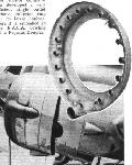
The Bristol company has developed a very efficient single-outlet exhaust collector ring for its latest engines. Here it is embodied in the N.A.C.A. cowling of a Pegasus-Douglas
-
Flight 1936-04 / Flight
In these three views the main features of a modern baffled installation are readily seen. The first two show the specially shaped "shoulder" which conducts the cooling air out of the "gills"; in the second the inter-cylinder baffles are visible, and the third shows the complete installation. The nose portion forms the exhaust ring. Actually this installation is of one of the 690 h.p. Bristol Pegasus III's in a Douglas D.C.2.
-
Flight 1936-02 / Flight
The Sperry in charge,at 9,000 ft. over Rheims, while the pilot, Mr. Nieffenegger, looks on before returning to his charts.
-
Aviation Historian 12 / E.Young - Over the Weather
A photograph in the September 1935 issue of Trade Winds magazine showing the oxygen masks Tomlinson and the DC-1 crew wore on the Kansas City-Newark flight of September 5 that year.
-
Flight 1938-01 / Flight
BLIND TRANSPORT: With the cockpit completely screened a T.W.A. pilot takes his regular blind-flying test (demanded every 90 days) under the eye of one of the line's chief pilots.
-
Flight 1936-04 / Flight
An interior view of the passengers' cabin of the Douglas. D.C.1 "Transport."
-
Flight 1935-06 / Flight
A view showing twelve of the fourteen passengers inside a standard Douglas D.C.2. as used by the majority of America's air transport companies.
-
Мировая Авиация 11
Пассажиры и пресса с восторгом отзывались о комфорте современного салона DC-2. В нем могли разместиться уже до 14 пассажиров с багажом, а не 12 пассажиров, как в DC-1.
-
Flight 1934-10 / Flight
A COMFORTABLE CABIN: Seating accommodation is provided in the Douglas D.C.2 for fourteen passengers. The seats are adjustable for height and angle.
-
Flight 1934-10 / Flight
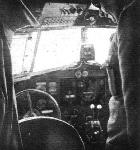
Oil temperature, carburetter temperature, mixture, the control-surface "tabs," petrol dumping, the throttles and the pitch of the Hamilton airscrews are all controlled from this compact assembly in the Douglas.
-
Aviation Historian 16 / K.Honey - In the Land of Black Gold
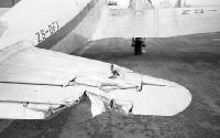
Регистрационный номер: ZS-DFX [3], F-BJHR [3], HB-ITO [3] Ouch! The tailplane of DC-2 ZS-DFX after its close encounter with the port propeller of a runaway DC-3. It was repaired and continued to fly with Silver City until it was acquired by French company Airnautic, with which it operated from Nice as F-BJHR. The hardworking DC-2 was withdrawn from service in the autumn of 1961 and was finally scrapped in 1964.
-
Air-Britain Archive 1990-03
Регистрационный номер: SP-ASK The photographs clearly show a wrecked DC-2 in Russian markings and with the letters ASK still faintly visible on the rear fuselage. They were taken at Spilve airfield, Riga in Latvia on the day of the invasion in July 1941 after a Luftwaffe attack had destroyed many Russian aircraft on the ground, two Ju 88s appear in the background. This confirms that SP-ASK did indeed escape to Latvia in 1939 but we are still left with the mystery of which LOT DC-2 crashed on 20.8.38.
Другие самолёты на фотографии: Junkers Ju.88 - Германия - 1936
-
Flight 1936-04 / Flight
A diagramatic representation of the noise level distribution in the cabin of the Douglas D.C.1 cruising at 75-80 per cent full power and carrying twelve passengers but no mail nor baggage.
-
Flight 1934-10 / Flight
Air vent, landing lights and pitot head on the Douglas D.C.2.
-
Flight 1934-10 / Flight
Each fixed surface in the empennage of the Douglas D.C.2 is carefully filleted where it joins the fuselage. This skeleton shows also the balancing of the movable surfaces and a portion of the trailing antenna.
-
Flight 1935-08 / Flight
THE HIDE-OUT: A friend of ours, of a retiring nature, having discovered in the German journal Luftwehr this crew-station diagram for a Fokker-Douglas D.C.2 bomber, has definitely decided on the position he would like to occupy in the event of finding himself in a heavy bomber squadron in the next war.
-
Flight 1934-10 / Flight
Другие самолёты на фотографии: Airspeed Courier / AS.5 - Великобритания - 1933Airspeed Envoy / AS.6 - Великобритания - 1934Boeing Model 247 - США - 1933Fairey Fairey IIIF - Великобритания - 1926Koolhoven FK-41 - Нидерланды - 1928Lockheed Orion 9 - США - 1931Messerschmitt Bf.108 Taifun - Германия - 1934Miles Hawk / M.2 - Великобритания - 1932Pander S-4 Postjager - Нидерланды - 1933
-
Flight 1934-10 / Flight
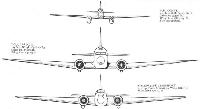
BIG CLAUS AND LITTLE CLAUS: Front elevations, to the same scale, of the De Havilland "Comet," the Douglas D.C.2, and the Boeing 247-D. These machines were first, second and third respectively to reach Australia.
Другие самолёты на фотографии: Boeing Model 247 - США - 1933De Havilland Comet / D.H.88 - Великобритания - 1934
-
Flight 1934-10 / Flight
SECOND TO REACH AUSTRALIA: The Douglas D.C.2 is similar to the D.C.1 shown in these general arrangement drawings. The engines are Wright "Cyclones" of 700 h.p. each.
-
Мировая Авиация 114
Douglas DC-2
Тип фотографий
- Все фото (143)
- Боковые проекции (2)
- Цветные фото (6)
- Ч/б фото (116)
- Кабина (8)
- Обломки (2)
- Схемы (9)


