
Описание
 Wiki
Wiki 
Страна : Великобритания
Год : 1936
Средний бомбардировщик с экипажем из четырех человек
Варианты
- Handley Page - Hampden / H.P.52 - 1936 - Великобритания
- Handley Page - Hereford / H.P.53 - 1937 - Великобритания
Авиаколлекция Бомбардировщики 1939-1945
Hampden / H.P.52
Средний бомбардировщик, двухмоторный цельнометаллический моноплан с двухкилевым оперением, убирающимся шасси с хвостовым колесом. Экипаж 4 - 5 человек. Спроектирован в КБ фирмы "Хэндли-Пейдж" под руководством Г.Лачманна. Первый полет совершил 21 июня 1936 г. Серийное производство начато в июне 1938 г. Выпускался заводами "Хэндли-Пейдж" (Криклвуд), "Шорт энд Гарланд" (Белфаст), "Инглиш электрик" (Сэмлсбюри), "Кэнедиэн асошиэйтед эйркрафт" (Мэлтон, Сент-Губерт). Всего построено 1580 экз.
Вооружение первых серий 4x7,69, последующих - 6x7,69; многие самолеты доработаны в частях в вариант 8x7,69. Бомбы до 1250 кг.
Самолет состоял на вооружении в Великобритании с августа 1938 г., в СССР - с октября 1942 г., в Канаде - с начала 1941 г.
Выпускался в двух основных вариантах:
- "Хэмпден" I с моторами "Пегасус" XVIII;
- "Хирфорд" I с моторами "Дэггер" VII.
С сентября 1939 г. "хэмпдены" применялись британскими ВВС для дневных и ночных операций над морем, включая постановку мин у побережья Германии. С декабря 1939 г. действовали только ночью, участвуя в налетах на цели в Германии, в т.ч. в августе 1940 г. в первом английском налете на Берлин. В конце 1940 г. вынужденно применялись как ночные истребители. Как бомбардировщики использовались до сентября 1942 г., затем были переделаны в торпедоносцы "Хэмпден" TBI (эксплуатировались до середины 1943 г.)
Самолеты "Хирфорд" в боевых условиях почти не применялись и служили в основном как учебные. В СССР самолеты модификации TBI имелись в ВВС Северного флота, где действовали как ночные бомбардировщики и торпедоносцы. В Канаде эти машины использовались только для учебных целей.
Производство прекращено в Англии в марте 1940 г. "Хэмпдены" сняли с вооружения в Великобритании в конце 1943 г., в Канаде - в конце 1944 г. Все советские "хэмпдены" были потеряны в боях к июню 1943 г.
"Хэмпден" I||
Размах:||21,01 м
Длина:||16,28 м
Моторы, количество х мощность:||2x10¹⁵ л.с.
Взлетная масса, максимальная:||8525 кг
Максимальная скорость:||406 км/ч
Практический потолок:||6920 м
Дальность:||1920 км
Описание:
- Авиаколлекция Бомбардировщики 1939-1945
- Авиаколлекция Морские самолеты палубного и берегового базирования 1939-1945
- Handley Page H.P.52 Hampden
- Flight, May 1939
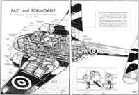
A VERY REMARKABLE AEROPLANE - Flight, November 1939
Britain's Military Aircraft
Фотографии

-

Мировая Авиация 118
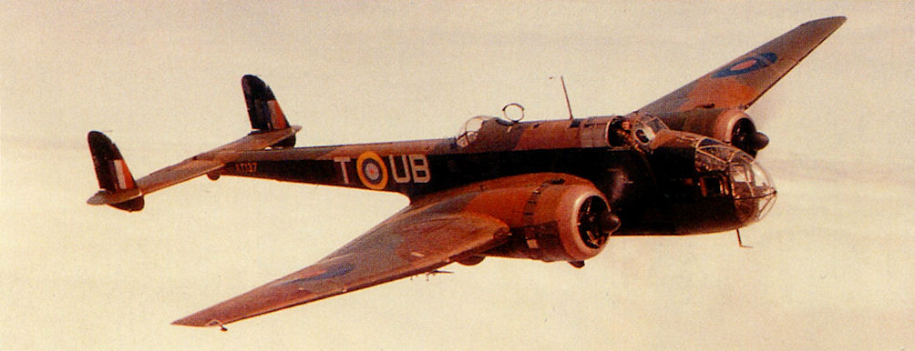
Регистрационный номер: AN127 Handley Page Hampden TB.Mk I. До поступления на вооружение торпедоносцев Beaufighter Mk VIC, прозванных "Torbeau", союзники использовали против вражеского судоходства в Северном море торпедоносцы/бомбардировщики Hampden TB.Mk I. Они также обеспечивали прикрытие конвоев, следовавших в Мурманск. Данный TB.Mk I принадлежал 489-й новозеландской эскадрилье.
-
История Авиации 29 / А.Медведь - Хроники Интрудеров /Ретроспектива/ (5)
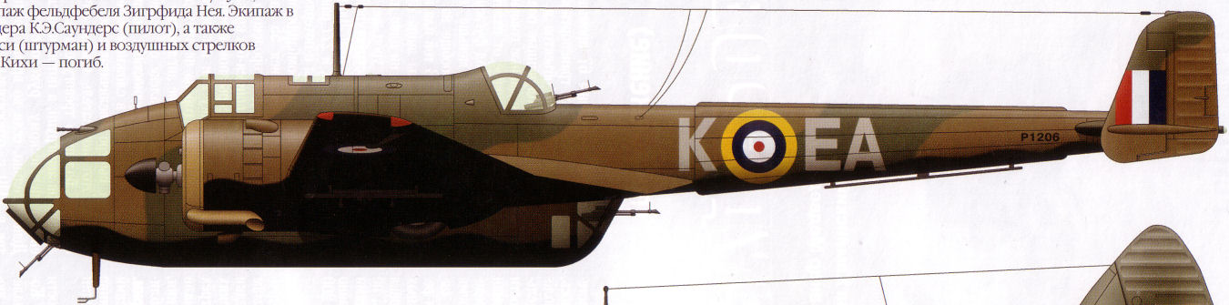
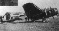
Регистрационный номер: P1206 "Хэмпден Mk.I" из состава 49-й эскадрильи, авиабаза Скэмптон, осень 1941г. Сбит в ночь на 9 ноября 1941г. над районом Бергена немецким ночным истребителем Bf110 из состава II/NJG2, который пилотировал экипаж фельдфебеля Зигфрида Нея. Экипаж в составе уоррент-офицера К.Э.Саундерс (пилот), а также сержантов Дж.М.Де'Арси (штурман) и воздушных стрелков С.Г.Малленгера и Дж.И.Кихи - погиб.
-
Мировая Авиация 117
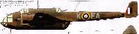
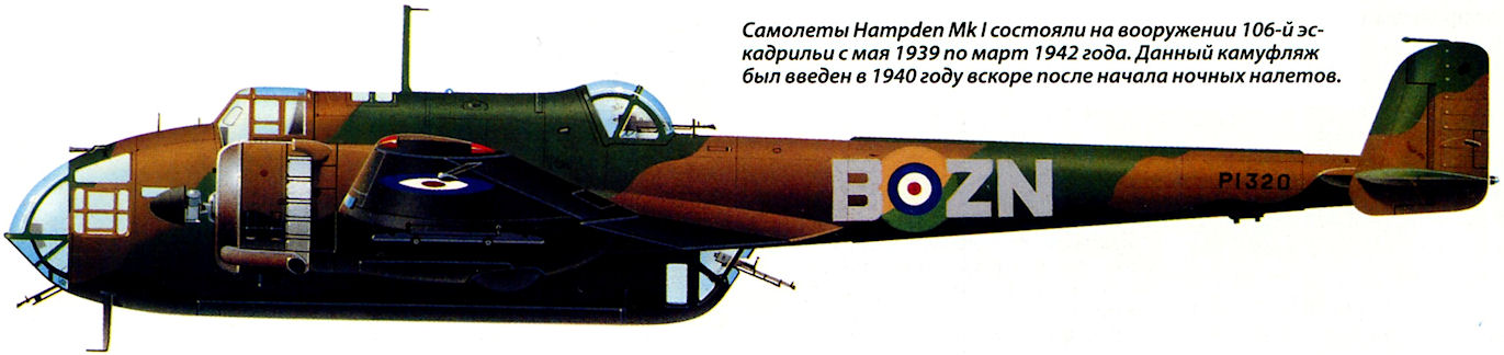
Регистрационный номер: P1320 Самолеты Hampden Mk I состояли на вооружении 106-й эскадрильи с мая 1939 по март 1942 года. Данный камуфляж был введен в 1940 году вскоре после начала ночных налетов.
-
История Авиации 29 / А.Медведь - Хроники Интрудеров /Ретроспектива/ (5)
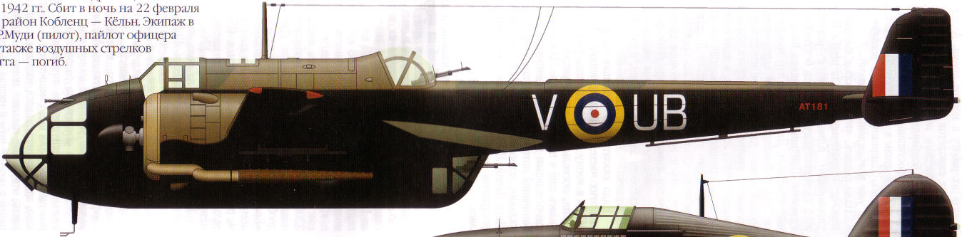
Регистрационный номер: P4414 "Хэмпден Mk.I" из состава 106-й эскадрильи, авиабаза Конигсби, зима 1941-1942гг. Сбит в ночь на 22 февраля 1942г. на маршруте в район Кобленц - Кельн. Экипаж в составе сержантов П.Д.Бишопа (пилот), Р.Ф.В.Хирста (штурман), а также воздушных стрелков Н.Д.Райта и Ф.Х.Дентона - погиб.
-
История Авиации 29 / А.Медведь - Хроники Интрудеров /Ретроспектива/ (5)
Регистрационный номер: AT181 "Хэмпден Mk.I" из состава 455-й эскадрильи, авиабаза Уигсли, зима 1941-1942гг. Сбит в ночь на 22 февраля 1942г. на маршруте в район Кобленц - Кельн. Экипаж в составе сержанта Дж.Р.Муди (пилот), пайлот-офицера Э.Т.Дэли (штурман), а также воздушных стрелков Дж.Дж.Дэвея и К.Р.Скотта - погиб.
-

Мировая Авиация 149
Данный самолет Hampden TB.Mk I, принадлежавший 455-й эскадрилье австралийских ВВС, показан в той окраске, какая у него была во время базирования в октябре 1942 года в Ваенге на советском Севере (ныне здесь расположена военно-морская база Североморск).
-

Мир Авиации 1995-01 / В.Котельников, Ю.Рыбин - "Балалайка" /В строю советских ВВС/
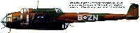
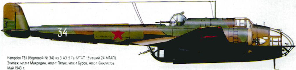
Hampden TB.I (бортовой N 34) из 3 АЭ 9 Гв. МТАП (бывший 24 МТАП). Экипаж: мл.л-т Макридин, мл.л-т Пятых, мл.с-т Буров, мл.с-т Феклистов.
-
Авиация и Время 2007-06 / А.Заблотский, Р.Ларинцев - Цель - Киркенес. От "булавочных уколов" к воздушному наступлению
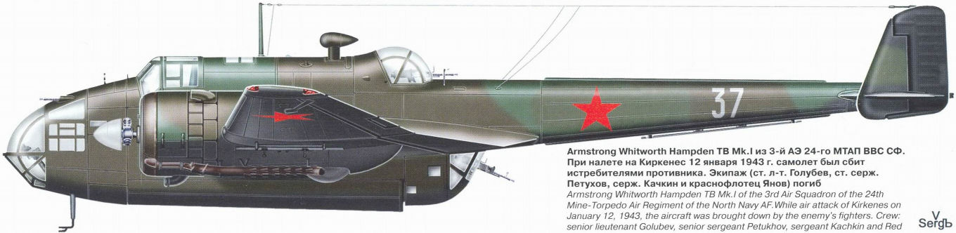
Armstrong Whitworth Hampden TB Mk.I из 3-й АЭ 24-го МТАП ВВС СФ. При налете на Киркенес 12 января 1943г. самолет был сбит истребителями противника. Экипаж (ст.л-т Голубев, ст.серж.Петухов, серж.Качкин и краснофлотец Янов) погиб
-

Мир Авиации 1995-01 / В.Котельников, Ю.Рыбин - "Балалайка" /В строю советских ВВС/
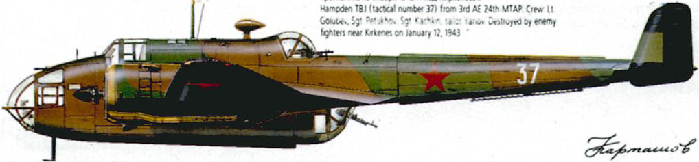
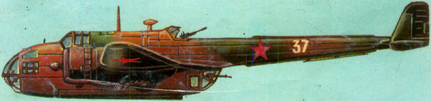
Hampden TB.I (бортовой N 37) из 3 АЭ 24 МТАП. Экипаж: ст.л-т Голубев, ст.с-т Петухов, с-т Качкин, краснофлотец Янов. Сбит истребителями противника 12 января 1943г. под Киркенесом.
-

Авиация и Космонавтика 1996-04 / В.Котельников, А.Артемьев - Минно-торпедная: авиация особого рода
Английский торпедоносец Хэндли-Пейдж "Хэмпден" TB-1 из 24-го минно-торпедного авиаполка ВВС Северного флота (начало 1943 года)
-

Мировая Авиация 199
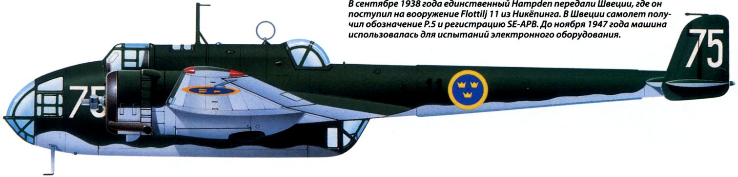
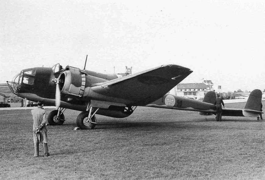
В сентябре 1938 года единственный Hampden передали Швеции, где он поступил на вооружение Flottilj 11 из Никёпинга. В Швеции самолет получил обозначение P.5 и регистрацию SE-APB. До ноября 1947 года машина использовалась для испытаний электронного оборудования.


-

Мировая Авиация 119
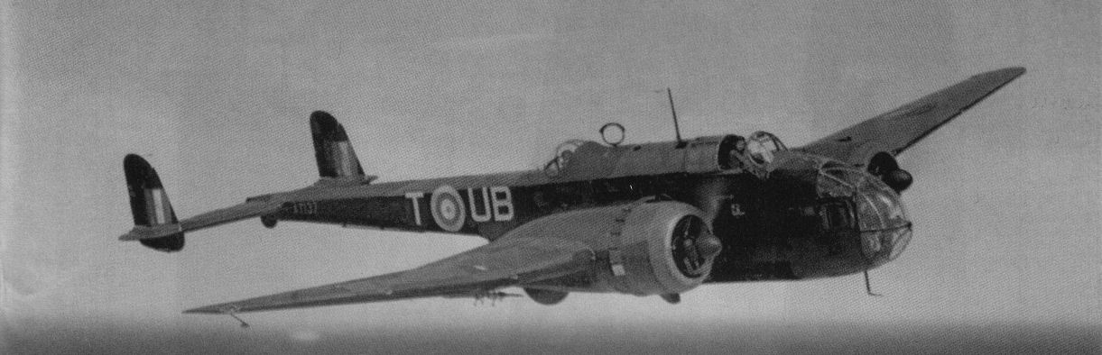
Регистрационный номер: AT137 [2] 455-я эскадрилья стала первой австралийской бомбардировочной частью, сформированной в Британии. Ее оснастили машинами Handley Page Hampden, а первым заданием стал удар по Франкфурту в ночь с 29 на 30 августа 1941 года.
-
Aeroplane Monthly 2000-04 / M.Oakey, T.Harmsworth - News
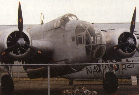
Регистрационный номер: P5436 [7] Hampden P5436, with mock-up engines and props fitted, looms over the fence at the Canadian Museum of Flight.
-

Aeroplane Monthly 1986-05 / A.Lumsden, T.Heffernan - Probe Probare (24)
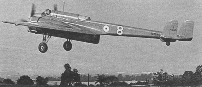
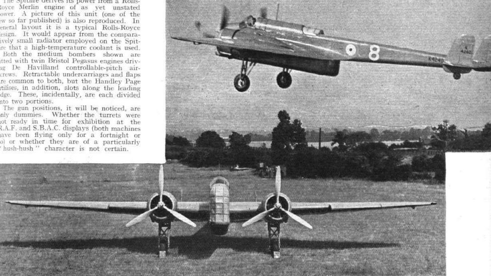
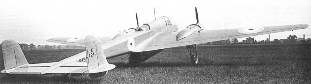
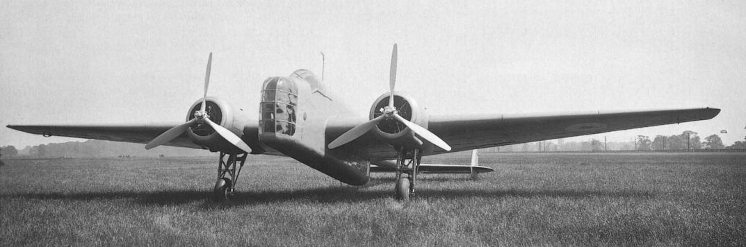
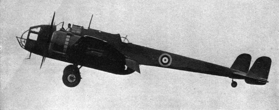
Регистрационный номер: K4240 [26] HIGH LIFT: HIGH SPEED. The new Handley-Page medium bomber with two Pegasus engines, controllable-pitch airscrews, slots and flaps, and retractable undercarriage. It is painted a sombre mud colour, which may signify a revision of official colour schemes.
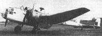
The H.P.52 prototype, with modified Heyford ventral turret, takes off from Radlett in July 1936. -

Aeroplane Monthly 1986-05 / A.Lumsden, T.Heffernan - Probe Probare (24)
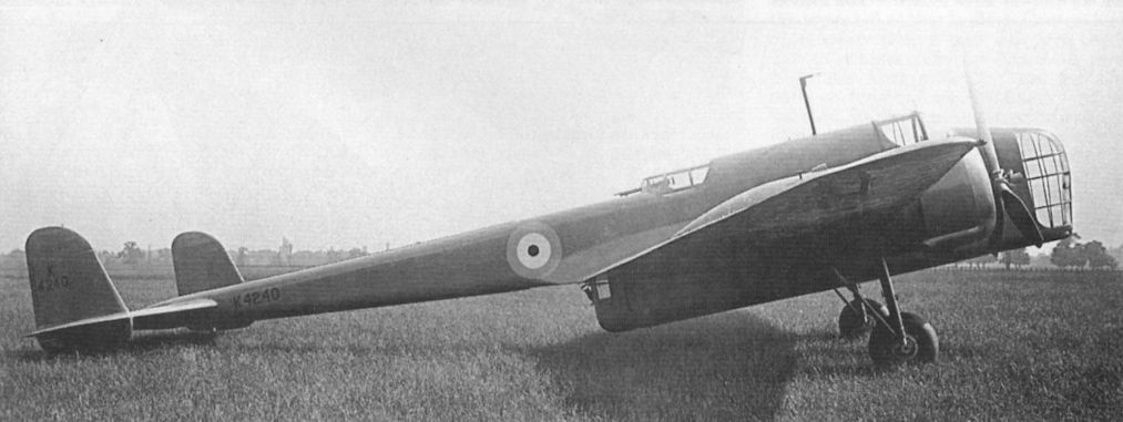
Регистрационный номер: K4240 [26] The same aircraft in its RAF Display configuration, with the nose glazing sheeted over with aluminium to hide its interior from public gaze.
-

-

Flight 1939-06 / Flight
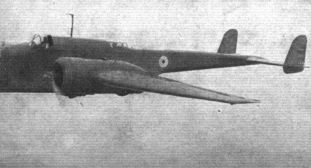
Регистрационный номер: K4240 [26] Прототип H.P.52 (K4240) был полностью окрашен глянцевой краской серо-зеленого цвета. Впервые самолет публично продемонстрировали в июле 1936 года на авиашоу британских ВВС в Хендоне.
K4240 photographed in the late summer of 1936; it was painted glossy grey-green all over. In the H.P.52 or Hampden slots and flaps have taken the place of the early plan form, and the power has gone up to about 1,500 h.p. -

Flight 1938-05 / Flight
Регистрационный номер: K4240 [26] The Handley Page Hampden (two Pegasus) will very soon be in service in considerable numbers. The nose of the production type will be more rounded than in the photograph.
-
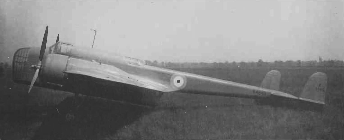
Flight 1936-11 / Flight
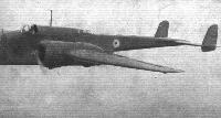
Регистрационный номер: K4240 [26] The striking lines of the H.P.52 medium bomber are well brought out here.
-

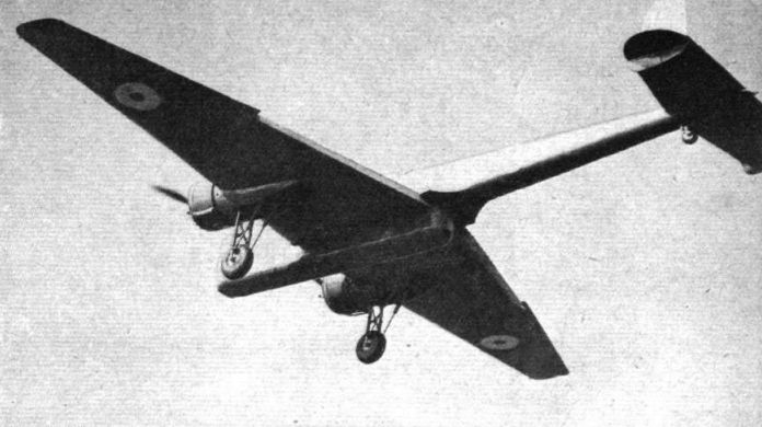
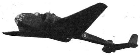
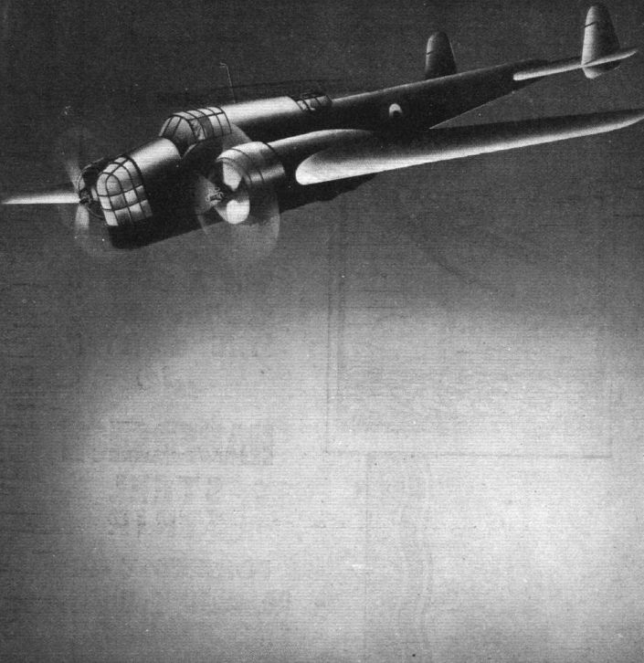
Flight 1936-07 / Flight
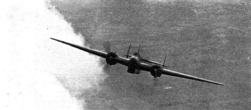
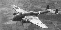
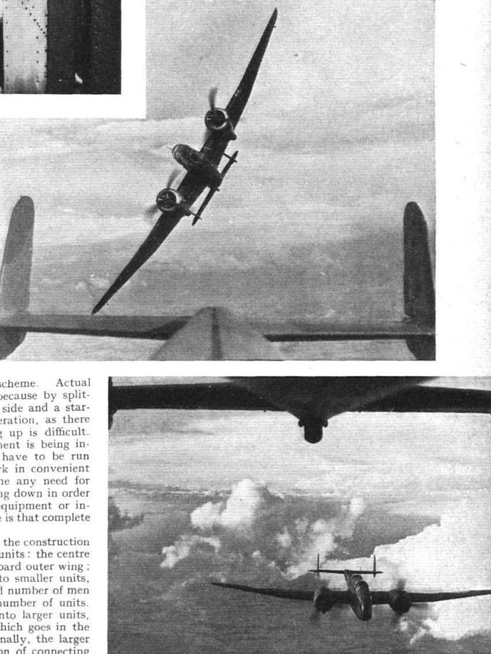
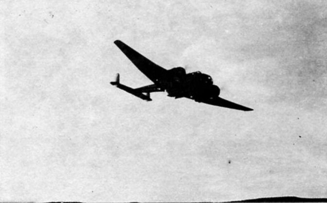
Регистрационный номер: K4240 [26] INTERCEPTOR FASHION: The climb of the new Handley Page medium bomber, in this striking picture, suggests the fighter of not so very many years ago.
-
Flight 1937-05 / Flight
Регистрационный номер: K4240 [26] VISIBLE PITCH: Careful study of this Flight photograph of a Handley Page Hampden will reveal spirals of vapour trailing from the airscrew tips. The photograph is untouched.
-

Flight 1939-06 / Flight
Регистрационный номер: K4240 [26] The Flight photograph referred to in the Editorial footnote to "Commonwealth’s" letter. The vortices visible at the airscrew tips have been very slightly touched-up for reproduction purposes, but they are just as clearly visible in the untouched original, and the picture is in no way "faked."
-

Flight 1936-07 / Flight
Регистрационный номер: K4240 [26] SLIM AND DARK: Off the ground, and with wheels retracted, the new Handley Page medium bomber (two Pegasus engines and C.P. airscrews) has a sinister beauty of line. For this photograph - the first taken with wheels up - the machine was "posed" by Capt J. B. L. H. Cordes, the makers' chief test pilot.
-

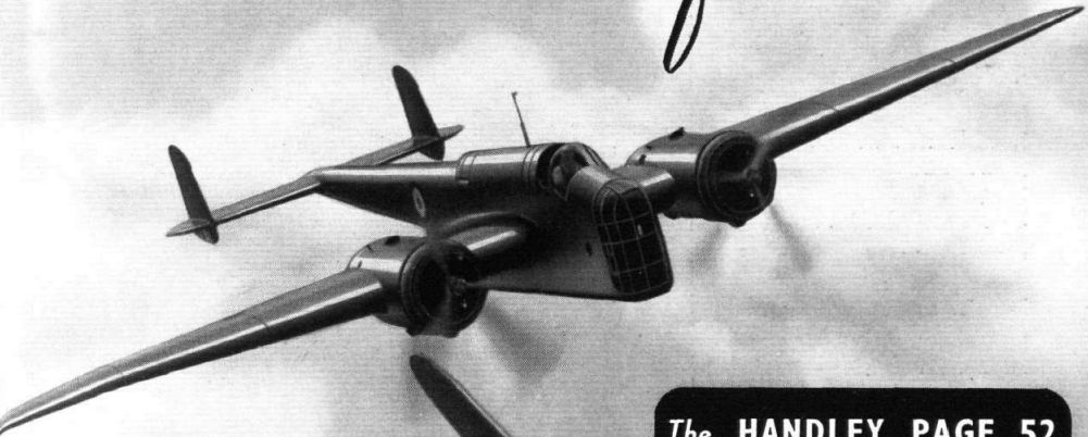
Flight 1936-08 / Flight Advertisements
Регистрационный номер: K4240 [26] -

Flight 1936-10 / Flight Advertisements
Регистрационный номер: K4240 [26] The HANDLEY PAGE 52 HEAVY BOMBER
-

Flight 1937-11 / Flight
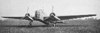
Регистрационный номер: K4240 [26] The prototype Handley Page Hampden medium bomber.
-

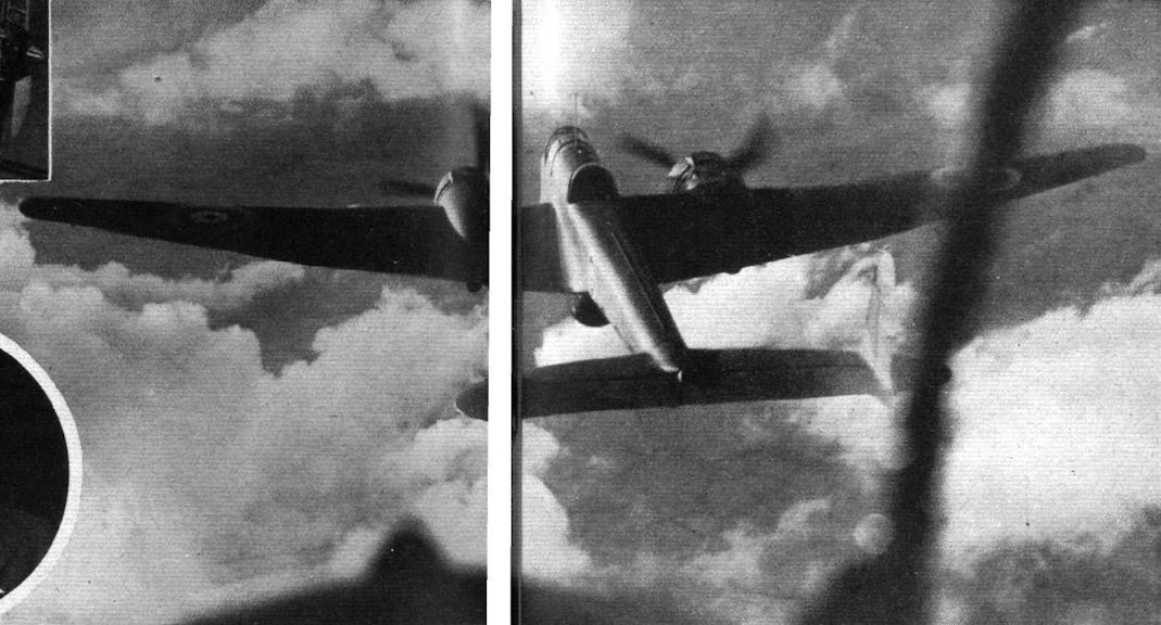
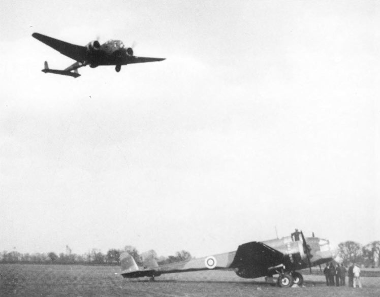
Flight 1939-06 / Flight
Регистрационный номер: K4240 [26] CLOSE-UP: Handley Page Hampden in rather startling proximity to another from which our photograph was taken.
-

Flight 1939-05 / Flight
Регистрационный номер: K4240 [26] The unimpeded view obtained from the compartment of the front lower gunner and bomber.
-

Flight 1939-06 / Flight
Регистрационный номер: K4240 [26] -

Flight 1937-07 / Flight
Регистрационный номер: K4240 [26] INCIDENTS at Hatfield last Tuesday: the H. P. Hampden.
-

Flight 1937-11 / Flight
Регистрационный номер: K4240 [26] Pegasus XX engines were specified for the Handley Page Hampden prototype shown here. An improved version is in production with Napier E.108s.
-

Aeroplane Monthly 1986-05 / A.Lumsden, T.Heffernan - Probe Probare (24)
Регистрационный номер: K4240 [26] K4240 photographed at Martlesham Heath.
-

Aeroplane Monthly 1986-05 / A.Lumsden, T.Heffernan - Probe Probare (24)
Регистрационный номер: K4240 [26] Another view of K4240 during one of its visits to Martlesham Heath.
-

Flight 1936-07 / Flight
Регистрационный номер: K4240 [26] PRESENTED TO HIS MAJESTY. This view of the King studying the retractable undercarriage on the new Handley Page medium bomber during his visit to Martlesham last week is but another illustration of His Majesty's genuine interest in things aeronautical.
-
Flight 1939-02 / Flight Advertisements
Регистрационный номер: K4240 [26] Cape. J. H. Cordes, Chief Test Pilot of Handley Page Ltd., goes aboard a Page Hampden.
-

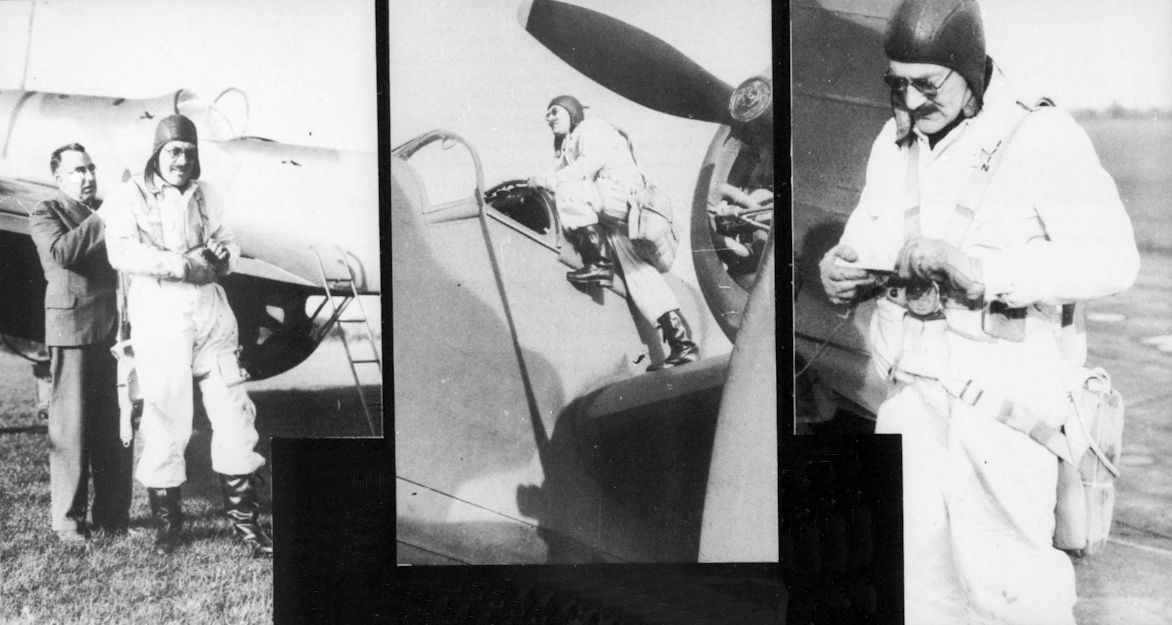
Aeroplane Monthly 1982-12 / D.Middleton - Maj James Cordes /Test Pilot Profile/ (5)
Регистрационный номер: K4240 [26] The three photographs show Maj Cordes preparing for a test flight in a Hampden at Radlett in 1938. Hampdens were constructed at Cricklewood and assembled and test flown at Radlett.
-
Air Enthusiast 2006-11 / F.Prins - Adaptable Stalwart /World War Two/ (1)
Регистрационный номер: K4240 [26] Handley Page's response to B9/32 was the HP.52 K4240. This entered production as the Hampden.
This view of the prototype H.P. 52 shows the small amount of wing dihedral. -

Flight 1936-12 / Flight
Регистрационный номер: K4240 [26] One of outstanding military types of 1936: The Handley Page Hampden.
-

Jane's All the World Aircraft 1980 / Encyclopedia of Aviation - Aircraft A-Z - v3
Регистрационный номер: K4240 [26] Handley Page Hampden prototype.


-

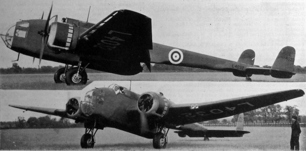
Jane's All the World Aircraft 1938 / 03 - All the world's aeroplanes
Регистрационный номер: L4032 [10] The Handley Page "Hampden" Medium Bomber (two Bristol "Pegasus" engines).
-

Flight 1938-06 / Flight
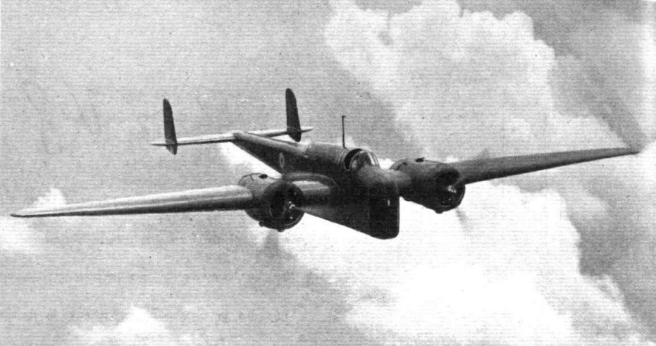
Регистрационный номер: L4032 [10] THE REVISED HAMPDEN: Liberal application of slots and flaps combines with clean design and Pegasus engines of the latest series to make the Handley Page Hampden bomber (seen here in its production form) one of the fastest machines of its calibre in the world.
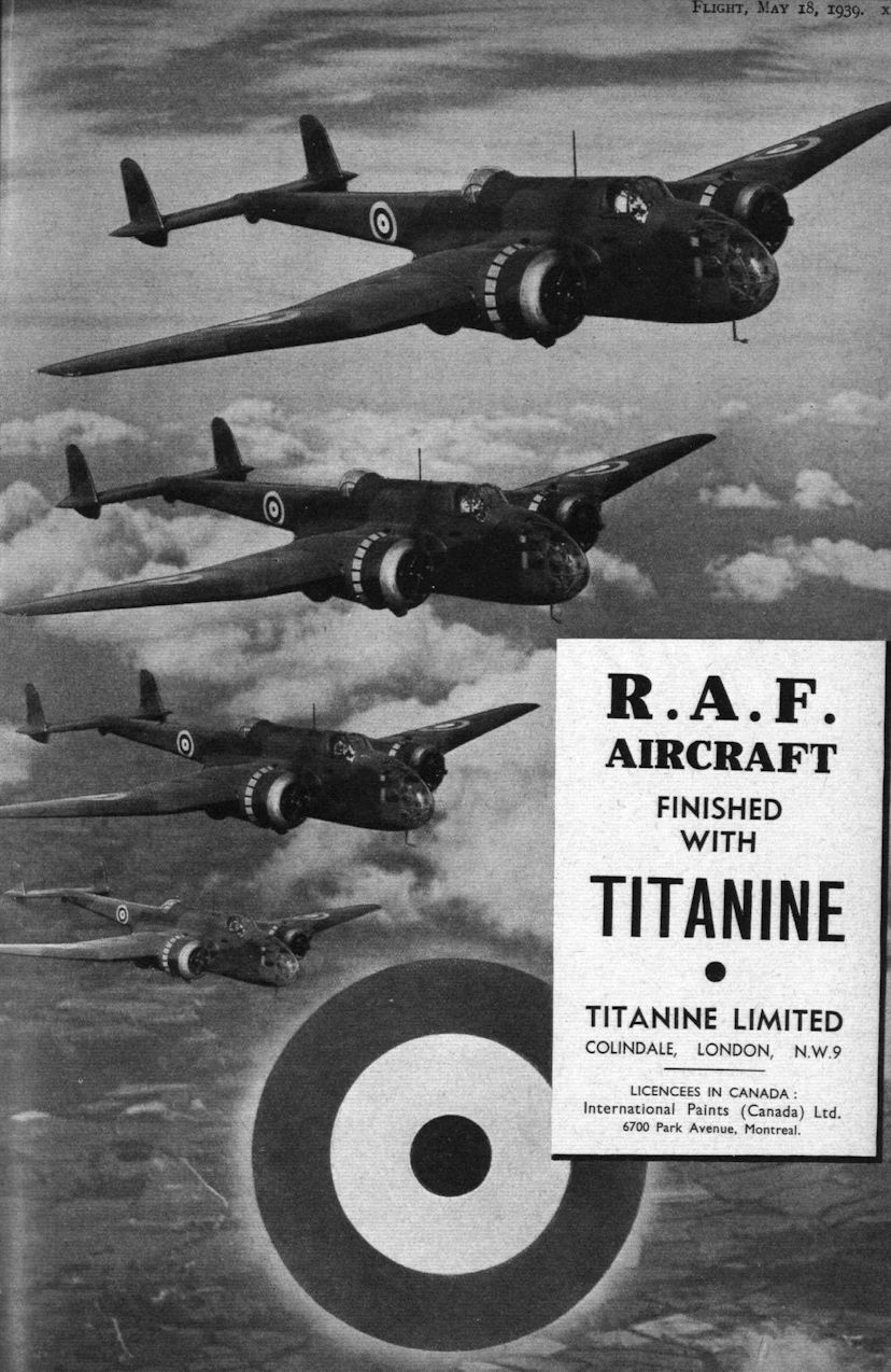
Well defended and able to carry a heavy load at high speed, the Handley Page Hampden, in production for the R.A.A.F., is a brilliant example of the modern twin-engined bomber -

Flight 1939-05 / Flight
Controllability is but one of the many strong points of the Hampden. Here Major Cordes shows it “formating” at 65 m.p.h. with wheels and flaps down.
-

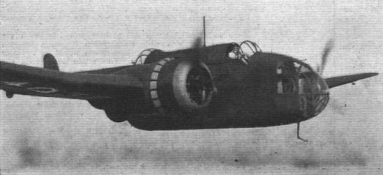
Flight 1940-05 / Flight
Since the beginning of the war the armament of the Hampden has been revised. It will be seen that there are twin Vickers K guns on upper and lower rear mountings and a movable gun firing downwards through the nose. A fixed Browning is provided for the pilot.
-

Air Pictorial 1995-04 / G.Swanborough - British aircraft at war, 1939-1945 (16)
A Hampden 1 bearing the prewar codes of No 66 Sqn at RAF Waddington.
-
Моделист-Конструктор Морские самолеты палубного и берегового базирования Второй мировой войны / В.Котельников - Морские самолеты палубного и берегового базирования 1939-1945 /Самолеты Второй Мировой войны/ (5)
Регистрационный номер: AT225 "Хэмпден" TB.I из 521-й эскадрильи Берегового командования, аэродром Докинг
-

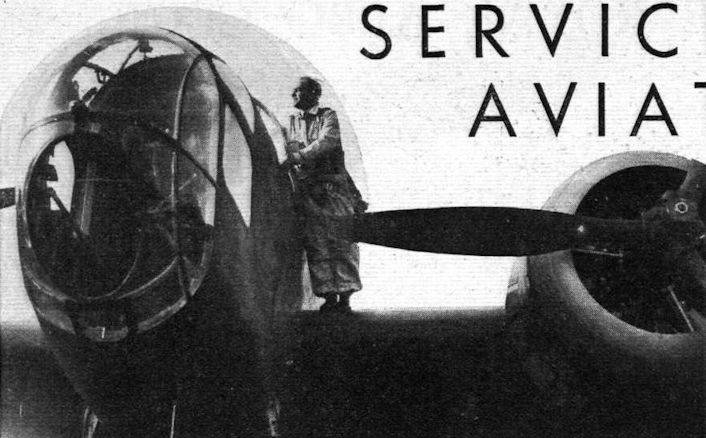
Flight 1939-03 / Flight
SEEING FOR HIMSELF: Mr. W. J. Sanderson, president of Fleet Aircraft of Canada, Ltd., Fort Eerie, Ontario, is an accomplished pilot, and he recently visited the Handley Page aerodrome at Radlett and flew a Hampden. His company, which is one of the manufacturing units of Canadian Associated Aircraft, Ltd., is to build Hampdens.
-

Aeroplane Monthly 1986-05 / A.Lumsden, T.Heffernan - Probe Probare (24)
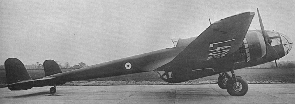
Регистрационный номер: L4032 [10] The production prototype Hampden, L4032, was first flown in May 1938. After evaluation by the A&AEE and RAE is was given the Maintenance serial number 2711M in 1941.
-

Air Enthusiast 1971-09 / H.Taylor - Flying the "Flying Suitcase" /Viewed from the Cockpit/
Handley Page Hampden I built in Canada and later converted into a torpedo bomber.
-
История Авиации 29 / А.Медведь - Хроники Интрудеров /Ретроспектива/ (5)
"Хэмпден Mk.I" из состава 106-й эскадрильи. Хорошо виден выпущенный предкрылок
-

Air Pictorial 1955-12 / Photos by request
Регистрационный номер: X3115 [2] HANDLEY PAGE H.P.62 HAMPDEN II. Published for the first time is a photograph of a Cyclone-powered Hampden II, the H.P.62 - in this case a standard English Electric, Preston-built Hampden, X3115 (in Coastal Command slate- and sea-grey camouflage) which served with No.415 (R.C.A.F.) Squadron from 1940 until permanently grounded in December 1943. This photograph was taken in England in January 1943 and reveals the unpainted, short-chord cowling of the 1,100-h.p. Wright GR1820-G102A 9-cylinder radials which replaced the normal 1,000-h .p . Bri stol Pegasus XVIIIs of the H.P. 52 Hampden I. At one time the Ministry of Aircraft Production had planned to fit Canadian-built Hampdens with Cyclones but the scheme never materialised. Other Cyclone installations included K4032 and and L4032. No other data available.
-

Flight 1939-05 / Flight
A few of the Hampdens which are now leaving Radlett aerodrome in a nice steady stream for “unknown destinations.”
-

Aeroplane Monthly 1981-02 / Radlett /Gone but not forgotten/ (9)
Регистрационный номер: L4080 Hampden L4080 at Radlett in February 1939. Powered by two 1,000 h.p. Bristol Pegasus XVIII radial engines, nearly 1,400 were built.
-
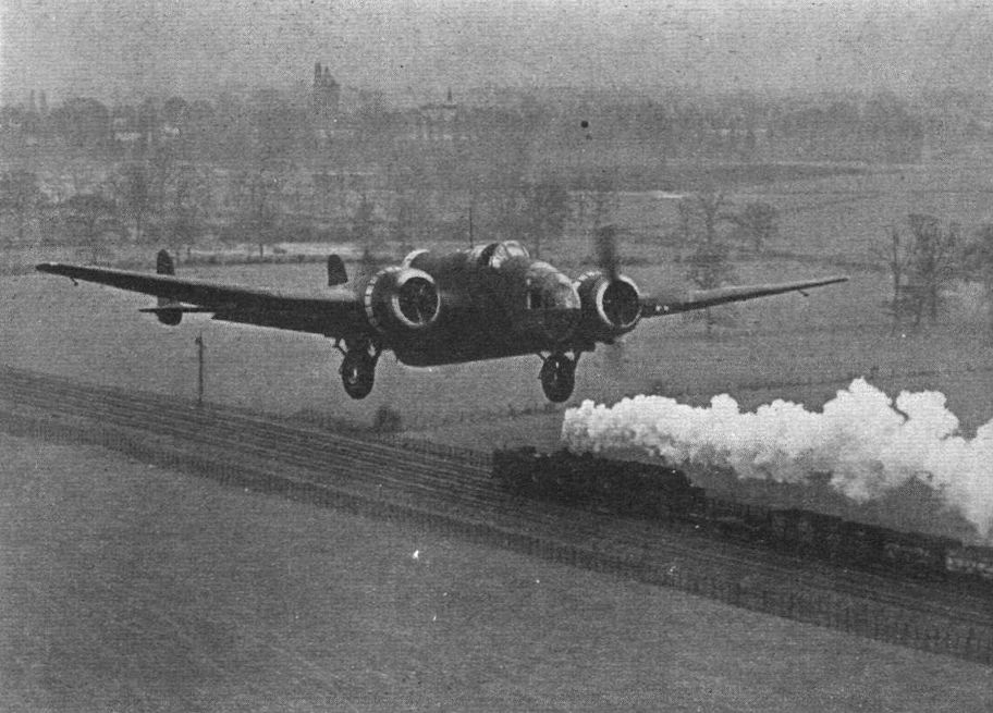
Flight 1939-04 / Flight
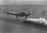
Регистрационный номер: L4135 [2] TRACTIVE EFFORT: Capt. J. H. Cordes retracts the undercarriage of a Hampden as he passes - on the L.M.S. line skirting Handley Page’s Radlett Aerodrome - a “Garratt” type locomotive, which is capable of a tractive effort of 45,620 lb. The combined take-off output of the Pegasus engines of the Hampden is between 1,900 and 2,000 h.p.
-

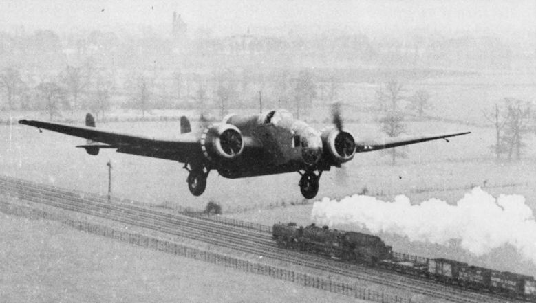
Aeroplane Monthly 1982-12 / D.Middleton - Maj James Cordes /Test Pilot Profile/ (5)
Регистрационный номер: L4135 [2] Cordes flying Hampden L4135 along the railway line at Radlett in April 1939. (First person to write in and tell us what type of locomotive is travelling in the opposite direction will receive a print of the photograph.)
-
Мировая Авиация 199
Регистрационный номер: X3115 [2] В войну самолеты Hampden выполняли самые разные задания, включая сброс листовок, дневные и ночные налеты, постановку морских мин, нанесение ударов торпедами.
Hampden II with Cyclone engines, distinguished by the short-chord cowlings.
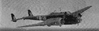
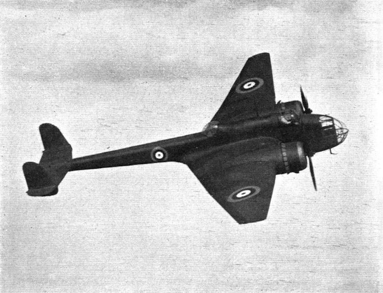
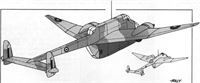
Balalaika. A number of Handley Page Hampdens were sent to Russia and given the musical-instrument nickname because of their profile. “Flying Tadpole” was one of the usual nicknames at home. In plan view, of course, Hampdens looked more like a champagne glass. -

Flight 1938-10 / Flight
Регистрационный номер: L4032 [10] The Handley Page Hampden (two Bristol Pegasus) follows the Harrow as the standard production type at the Handley Page works;
-

Flight 1940-02 / Flight Advertisements
Регистрационный номер: L4032 [10] Handley Page HAMPDEN in quantity production for the RAF.
-

Flight 1939-05 / Flight Advertisements
Регистрационный номер: L4032 [10] -

Flight 1938-06 / Flight
Регистрационный номер: L4032 [10] PROBOSCIDAL MODS: The new nose of the Handley Page Hampden bomber (two Pegasus) as now in quantity production. Deliveries will start very shortly. Note the dihedral on the wings and the revised gun position.
-

Jane's All the World Aircraft 1938 / 03 - All the world's aeroplanes
Регистрационный номер: L4032 [10] The Handley Page "Hampden" Medium Bomber (two Bristol "Pegasus" engines).
-

Aviation Historian 29 / G.Baughen - 1939. Was the RAF ready to war?
Регистрационный номер: L4032 [10] THE HANDLEY-PAGE "HAMPDEN": two “Bristol” Pegasus XX engines, with C.P. airscrews. A mid-wing monoplane day and night bomber-fighter of all-metal construction with flush riveting and stressed skin; fitted with the H.P. flapped-and-slotted wing system, giving a wide speed range. Retractable undercarriages and tail-wheel. The crew of four are accommodated in enclosed cockpits giving three gun positions. No details of performance may be given, but manoeuvrability, speed and capacity are notable characteristics. Built by Handley-Page Ltd.
The Handley Page Hampden was the last of the RAF’s twin-engined monoplane bombers to go into service before the outbreak of war. While it had no power-operated gun turrets, it was fast and manoeuvrable with fighter-like handling.
The single-pilot Handley Page Hampden was dubbed “the flying suitcase” by The Aeroplane’s Editor, C.G. Grey owing to its extremely slim fuselage. Interestingly, a German intelligence assessment of the time rated the Hampden as the RAF’s best bomber. -

-

-
История Авиации 29 / А.Медведь - Хроники Интрудеров /Ретроспектива/ (5)
Регистрационный номер: AT137 [2] -

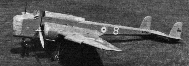
Flight 1938-08 / Flight
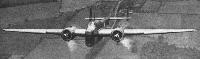
TRAPEZOIDAL: The unusual plan form of the Handley Page Hampden is well brought out in this picture. The machine is now in large-scale production at Cricklewood, where, the makers claim, the new system will “result in a peak rate of production at least twice that of the Harrow for the same floor space.”
-

Aeroplane Monthly 1994-03 / J.Maynard - Pickard, hero of Amiens (1)
Bomber Command’s standard heavy aircraft at the outbreak of war were the Hampden, in the background, and the Wellington, both flown by Pickard during his career.
Другие самолёты на фотографии: Vickers Wellington / Type 271 - Великобритания - 1936
-

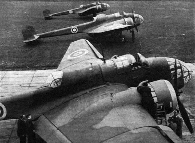
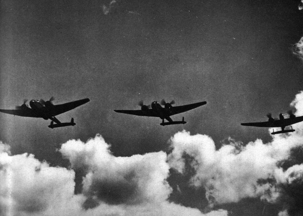
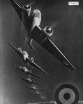
Flight 1940-05 / Flight
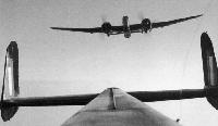
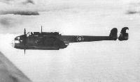
The sharply-tapered wings and the slim rear fuselage of the Hampden are evident in this view of a formation. It will be seen that the bomb doors are open.
-

-

-

-
Мировая Авиация 117
Handley Page Hampden не обладал адекватным для защиты от истребителей оборонительным вооружением, и в дневных налетах они несли тяжелые потери.
-

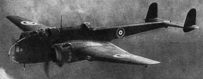
Aeroplane Monthly 1985-03 / L.Coombs - The expanding years 1936-1939 (5)
PEGASUS-POWERED: Handley Page Hampden I bombers on a practice flight. The Hampden is powered with two Bristol Pegasus XVIII engines and has a top speed of 265 m.p.h. The armament is four machine guns.
Last of the RAF’s twin-engined bombers to go into service, the Hampden was used extensively during the early part of the war, initially with 49 Sqn. Eight Hampden squadrons were ready on declaration of war in September 1939. -

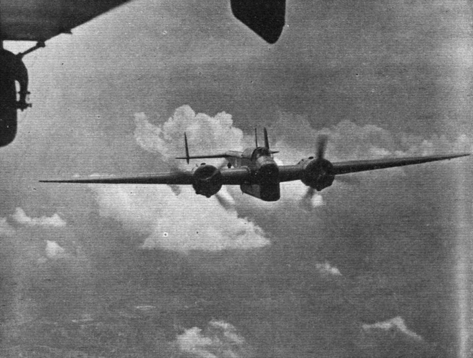
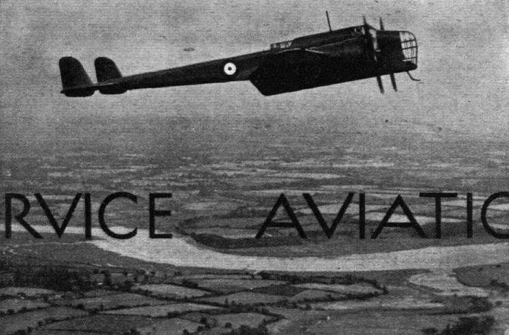
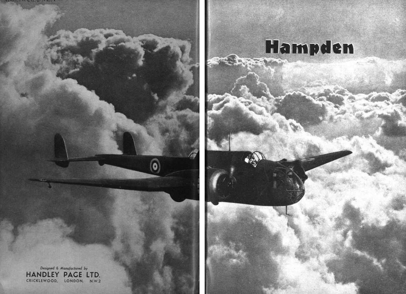
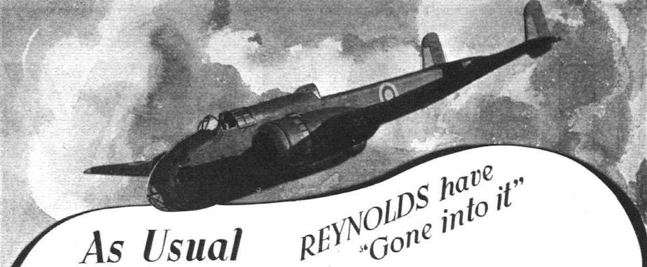
Flight 1939-05 / Flight
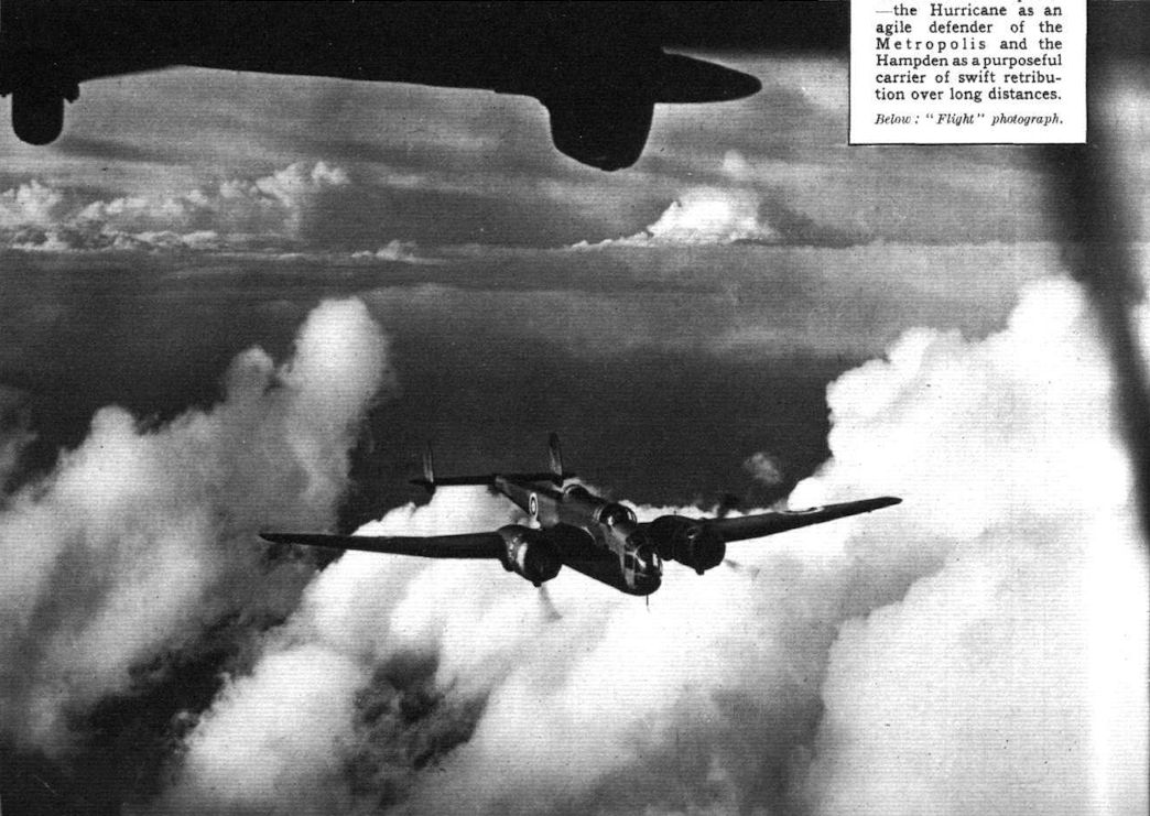
Cloudscape which give an oddly symbolic impression of the duties of the machine depicted - the Hampden as a purposeful carrier of swift retribution over long distances.
-

Flight 1940-09 / Flight
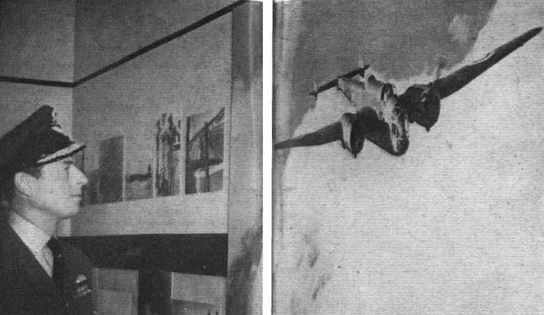
The Duke of Kent admiring a big enlargement of a Flight photograph of a Handley-Page Hampden.
-

-

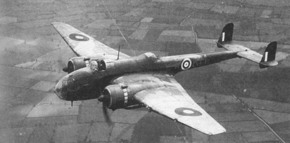
Aeroplane Monthly 1985-02 / L.Coombs - The expanding years 1936-1939 (4)
STRIKING POWER. Handley Page Hampden bombers of a type which composes a large portion of our bomber force. Although in service in large numbers the Hampden is still among the most efficient bombers in the world.
Last of the twin-engined bombers to go into RAF service during the expansion was the Handley Page Hampden bomber. -

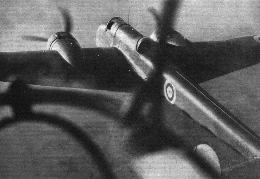
Flight 1940-05 / Flight
"Line astern" by Hampdens as seen from the lower gun position on a machine of the same type.
-

Aeroplane Monthly 1989-11 / I.Masson - Tinfish Hampdens
Регистрационный номер: L4105 [4] Hampden L4105 on torpedo exercises off Northern Scotland.
-
-
Мировая Авиация 199
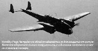
На этой фотографии хорошо видно, каким узким был фюзеляж Hampden, за который самолет и прозвали "The Flying Suitcase".
-

Flight 1939-05 / Flight
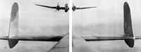
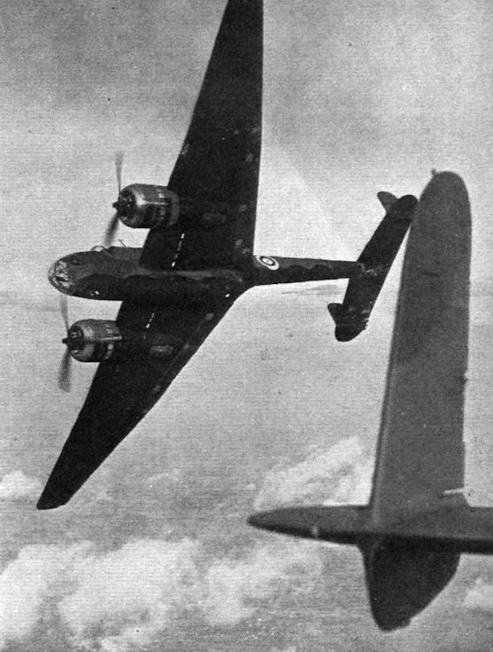
There are two rear gun positions in the Hampden, an upper and a lower. How unhindered are the fields of view and fire obtained from them is shown in the pictures. Major Cordes gives a good illustration of the Hampden as a fighter bomber.
-

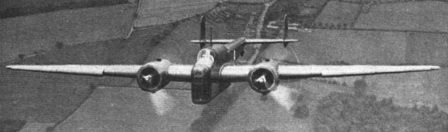
Flight 1939-05 / Flight
Регистрационный номер: L4143 [3] The manoeuvrability and the clear arcs of fire justify the makers in terming the Hampden a fighter bomber. On the occasion depicted, its agility was being demonstrated by Major Cordes. The photographic Hampden was piloted by Flt. Lt. J. R. Talbot.
-

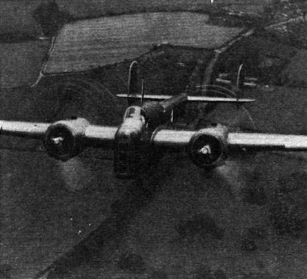
Flight 1940-04 / Flight
Регистрационный номер: L4143 [3] IN THE NEWS. It is now confirmed that a considerable proportion of aircraft used in the night attack on Sylt were Handley Page Hampdens.
The Handley Page Hampden bomber is extremely efficient, due in a large measure to the installation of Handley Page slots and flaps
Maj Cordes displays Hampden I L4143 for Flight’s photographer, 1938. -

Aeroplane Monthly 1989-11 / I.Masson - Tinfish Hampdens
Регистрационный номер: L4143 [3] Hampden I L4143 seen from the nose of another Hampden on April 6, 1939. L4143 crashed at night near RAF Kirton-in-Lindsey in April 1940.
-

Flight 1939-05 / Flight
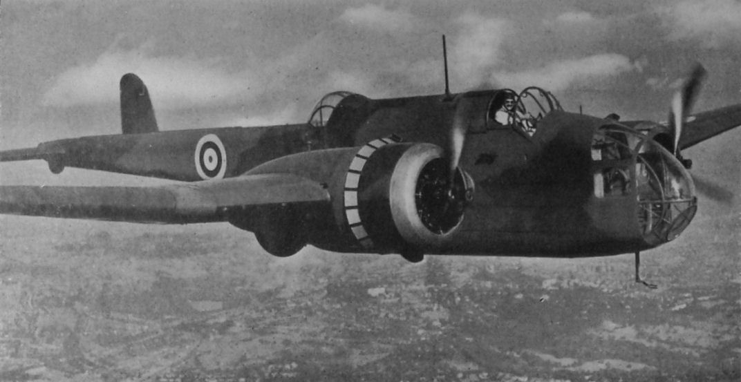
Handley Page Hampden bombers, which, like the Blenheims, are outstanding examples of the work of an old-established manufacturer.
-

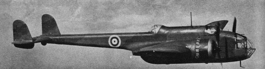
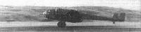
Flight 1939-06 / Flight
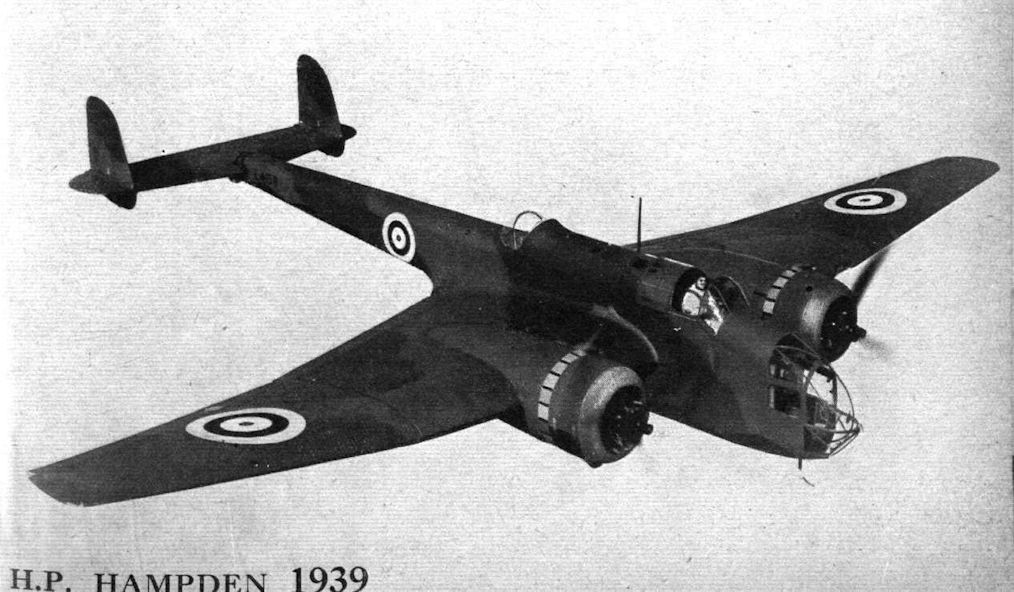
Бомбардировщик "Хэмпден" I в полете
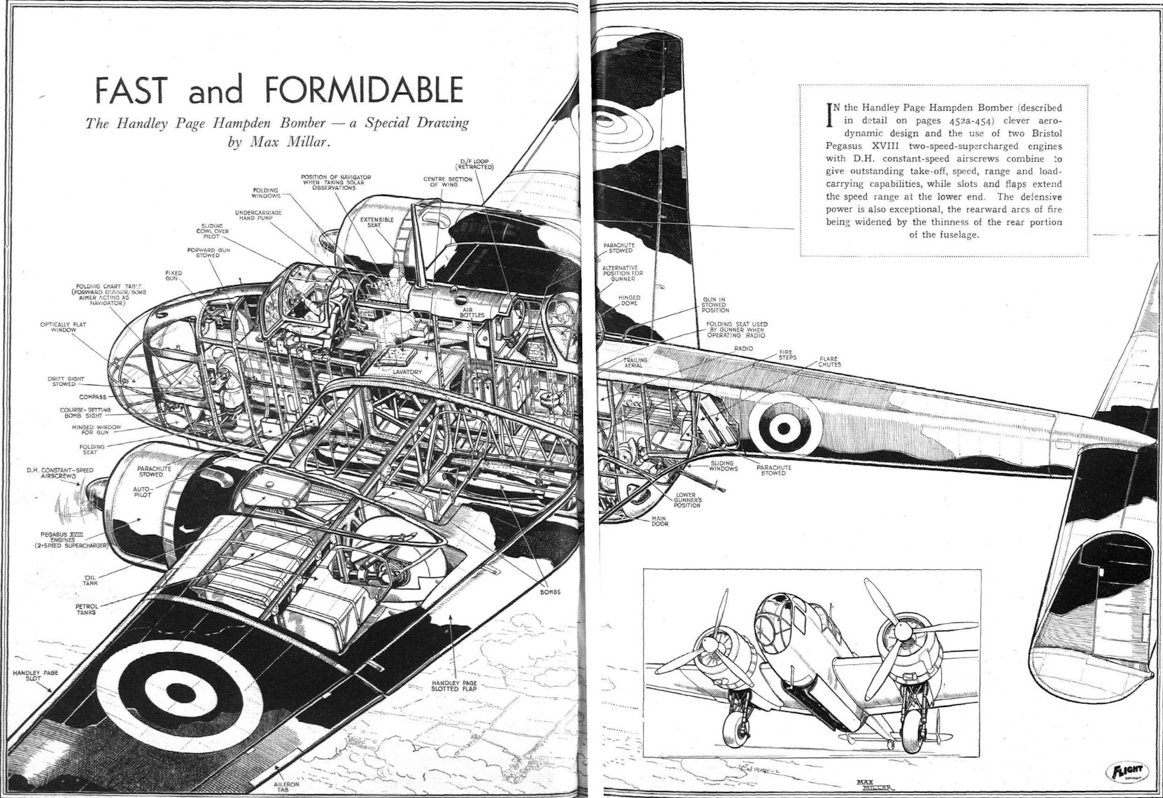
Development: The production version of the Hampden, a bomber of outstanding merit. -

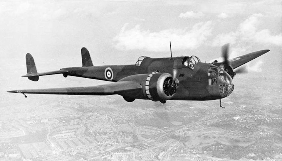
Flight 1939-11 / Flight
Fitted with two Bristol Pegasus XVIII engines the Handley Page Hampden bomber has a top speed 265 m.p.h. It is armed with four machine guns.
-
Моделист-Конструктор Бомбардировщики Второй мировой войны / В.Котельников - Бомбардировщики 1939-1945 /Самолеты Второй Мировой войны/ (2)
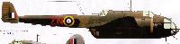
"Хэмпден" I из 44-й эскадрильи британских ВВС, 1940 г.
-

-

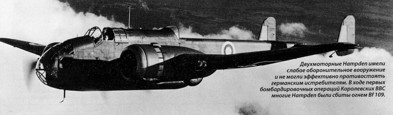
Мировая Авиация 54
Двухмоторные Hampden имели слабое оборонительное вооружение и не могли эффективно противостоять германским истребителям. Входе первых бомбардировочных операций Королевских ВВС многие Hampden были сбиты огнем Bf 109.
-
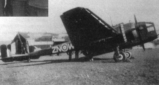
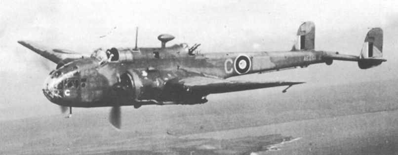
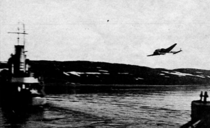
Aeroplane Monthly 1986-06 / R.Nesbit - Arctic Venture (5)
This Hampden is seen returning from a mission off the Norwegian coast with much of the port rudder shot away by flak - winter 1942-43.
-

-

Air Enthusiast 1971-09 / H.Taylor - Flying the "Flying Suitcase" /Viewed from the Cockpit/
Регистрационный номер: AE202, AE257 -

Мировая Авиация 52
185-я эскадрилья, входившая в состав 5-й группы Бомбардировочного командования, использовала бомбардировщики Hampden (на снимке) и одно звено ненадежных Hereford с моторами Dagger. Номинально эта часть считалась учебной.
-

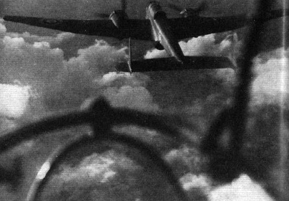
Flight 1940-05 / Flight
Its ease of control makes the Hampden a pleasant machine to fly in formation. Here is a compact stepped-up echelon.
-

Flight 1940-05 / Flight
There is a suggestion of "Mayo" influence about this view of two Hampdens flying in close company. Formation-flying is, of course, highly important in the training of a bomber pilot.
-

Flight 1940-05 / Flight
A flight of Hampdens, with open bomb doors, sweeps across the aerodrome, simulating a low-flying attack.
-
Мировая Авиация 199
Новозеландская 489-я эскадрилья летала на торпедоносцах-бомбардировщиках Hampden из Льючерза с марта 1942 года по декабрь 1943 года.
-

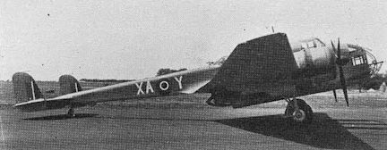
Air Pictorial 1995-04 / G.Swanborough - British aircraft at war, 1939-1945 (16)
Hampden TB Mk 1 in service with RNZAF-manned No 489 Sqn, in 1942. The code letters XA appear to have been overpainted.
-

Aeroplane Monthly 1989-11 / I.Masson - Tinfish Hampdens
A torpedo drops away from a Hampden during a practice exercise. Coastal Command squadrons Nos 144, 415, 455 and 489 used the Hampden as a torpedo-bomber.
-

Aeroplane Monthly 1989-11 / I.Masson - Tinfish Hampdens
A practice torpedo drop by a Handley Page Hampden. The torpedo is about to enter the water with a good angle of entry.
-

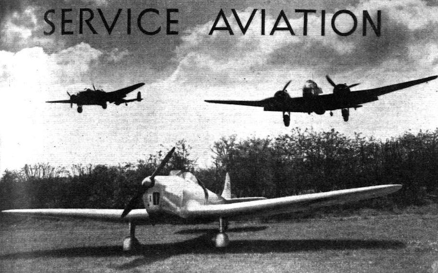
Flight 1939-10 / Flight
LOW APPROACH: Thanks to its slots and flaps the Handley Page Hampden can be operated from small aerodromes. A pair of Hampdens are seen approaching low with a Miles Magister in the foreground.
Другие самолёты на фотографии: Miles Magister / M.14 - Великобритания - 1937
-

-

Flight 1940-05 / Flight
The view from the nose of the Hampden is exceptionally good, greatly facilitating the work of the navigator-bomb aimer.
-

-

-

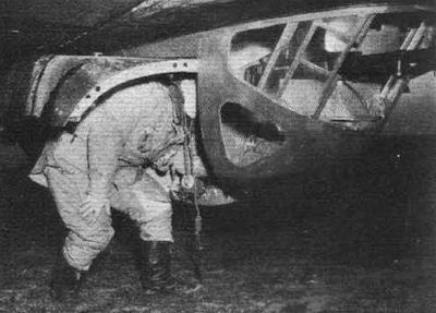
Flight 1940-08 / Flight
The picture of an air gunner emplaning on a Hampden shows clearly the twin Vickers K guns and the armour plate protection against enemy bullets and flying shrapnel.
-

Flight 1939-05 / Flight
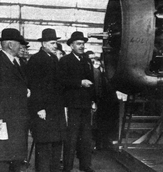
CAPT. BALFOUR, Under-Secretary for Air, sees Hampdens in production. On the right is Mr. Handley Page and on the left Rear-Admiral Sir Murray Sueter.
-

Flight 1938-06 / Flight
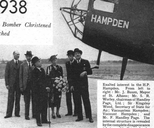
Exalted interest in the H.P. Hampden. From left to right : Mr. J. Baum, Mayor of St. Albans; Mr. S. R. Worley, chairman of Handley Page, Ltd. ; Sir Kingsley Wood, Secretary of State for Air; Viscountess Hampden; Viscount Hampden; and Mr. F. Handley Page. The internal structure is revealed by the complete disappearance (photographically) of the moulded Perspex windows.
-

Flight 1938-12 / Flight
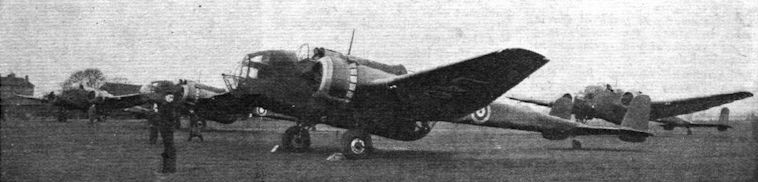
HAMPDENS about to leave their makers aerodrome for delivery to squadrons.
-

Flight 1938-06 / Flight
Регистрационный номер: L4032 [10] The Handley Page Hampden medium bomber (two Bristol Pegasus) posing for its portrait after last Friday's ceremony.
-

-

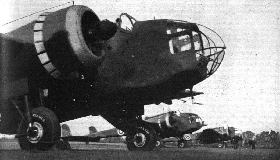
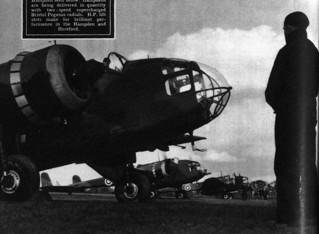
Flight 1939-03 / Flight
Hampdens being delivered in quantity with two-speed supercharged Bristol Pegasus radials. H.P. lift slots make for brilliant performance in the Hampden and Hereford.
-
Мировая Авиация 117
Боевой дух личного состава Бомбардировочного командования в начале войны сильно упал из-за тяжелых потерь, понесенных в дневных налетах.
-
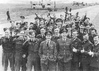
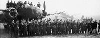
История Авиации 29 / А.Медведь - Хроники Интрудеров /Ретроспектива/ (5)
Летный состав 106-й эскадрильи 5-й авиагруппы Бомбардировочного Командования вместе со своим командиром уинг коммандером Гаем П.Гибсоном (на снимке стоит впереди всех) позирует после успешно проведенных ночных вылетов. На заднем плане видны бомбардировщики "Хэмпден" (слева) и "Манчестер" (справа). Судя по всему, фото сделано в период между февралем и маем 1942г., когда 106-я эскадрилья осваивала самолеты последнего типа. Уже в мае она начала оснащаться четырехмоторными "Ланкастерами Mk.IB". Авиабаза Конигсби.
Другие самолёты на фотографии: Avro Manchester / Type 679 - Великобритания - 1939
-

Flight 1940-04 / Flight
"WELL, WE DIDN'T DO SO BADLY." The pilot of a Hampden discusses experiences with his crew on their return from the raid on Sylt.
-

Aeroplane Monthly 1989-11 / I.Masson - Tinfish Hampdens
Регистрационный номер: L4105 [4] AC1s Oldland and Hugill, fitter and rigger, servicing L4105 at RAF Leuchars.
-

Flight 1940-09 / Flight
MINENWERFER: Loading a Handley Page Hampden with a parachute mine. The dropping of these mines goes on every night and is very exacting work. It calls for extremely accurate navigation, since narrow channels have to be found during the hours of darkness, and sometimes under heavy anti-aircraft fire.
-

Flight 1940-08 / Flight
Meanwhile whichever type of aircraft is being used for the job in hand, Whitley, Hampden or Wellington, the ground crews are busy loading up bombs, rearming gun turrets and giving engines and aircraft a final look-over.
-

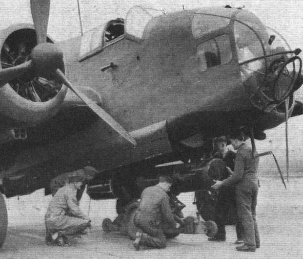
Aeroplane Monthly 1986-05 / A.Lumsden, T.Heffernan - Probe Probare (24)
Регистрационный номер: P1333 Hampden I P1333 being bombed up in 1940. The maximum bomb load was 4,000 lb. P1333 served with 49 Squadron and went missing on August 17, 1940. It was one of a batch of 200 Hampden Is delivered to the RAF between June 1939 and February 1940.
-

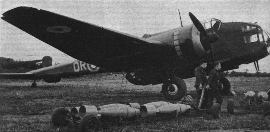
Flight 1940-04 / Flight
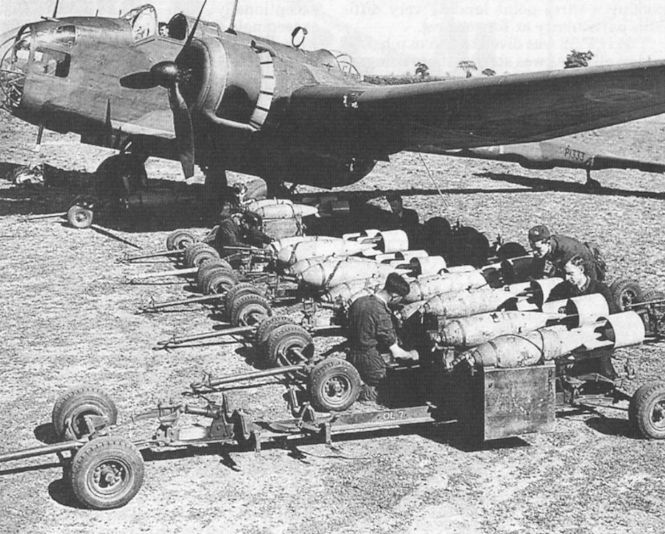
Newly loaded bomb racks form the centre of photographic interest at a Hampden station which sent machines to attack German warships off Bergen.
-

Flight 1940-05 / Flight
A pair of 500-lb. bombs being loaded, complete with carrier, into a Hampden.
-

Flight 1940-04 / Flight
The crew of a Hampden which, with many others of its kind, co-operated with naval forces in attacking warships off Bergen. It will be noted that the Hampden's rear armament has been doubled. There are two Vickers K guns in each of the upper and lower positions.
-

Flight 1940-05 / Flight
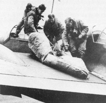
Dinghy drill. Members of the crew are abandoning a Hampden and the dinghy is seen inflating.
-

Aeroplane Monthly 1979-10 / F.Adkin - Memoirs of Aircraftsman (10)
A Hampden crew practise emergency ditching procedure with the dinghy on the wing.
-

Flight 1940-05 / Flight
Frequent exercise is given in the correct method of abandoning an aircraft with parachutes. Two members of the crew demonstrate how they would leave over the trailing edge of the wing.
-
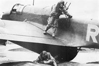
Aeroplane Monthly 1979-10 / F.Adkin - Memoirs of Aircraftsman (10)
The pilot about to jump into the inflated dinghy.
-

Flight 1940-05 / Flight
Dinghy drill. They are all aboard. The cylinder of CO2 can be seen on the side of the dinghy.
-

Flight 1940-05 / Flight
Frequent exercise is given in the correct method of abandoning an aircraft with parachutes. The nagivator-bomb aimer makes his exit head first through the floor.
-

Aeroplane Monthly 1989-11 / I.Masson - Tinfish Hampdens
Hampden crew at RAF Leuchars in December 1943. From left to right: Fg Off Lennox (WOp/AG), author (pilot), Fg Off Skidmore (navigator) and Fg Off Tyler (WOp/AG).
-
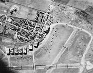
Air-Britain Aeromilitaria 1991-04
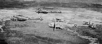
Henleys, Bothas and Hampdens are visible on this airfield.
Last month's airfield photograph was of West Freugh which took a little research. Although JJH had been into West Freugh a couple of times in an Anson in 1945, it was not remembered as having so many hangars!Другие самолёты на фотографии: Blackburn Botha / B-26 - Великобритания - 1938Hawker Henley - Великобритания - 1937


-
Air-Britain Aeromilitaria 1997-03 / Picture pages
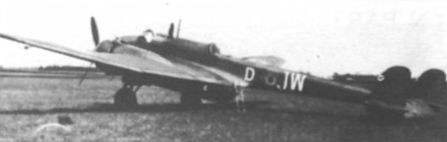
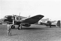
The SAAB-18 might have been a Hampden if Sweden had taken up its option to build the type under licence in 1939. The sole example is seen at Heston on delivery on 22 September 1938
-

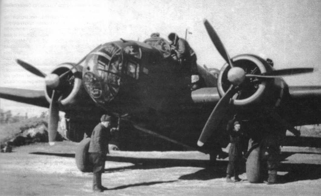
АвиаМастер 1999-04 / Ю.Рыбин - Expertenstaffel за Полярным кругом /Боевой путь/ (4)
Торпедоносец "Хэмпден" из 3-й эскадрильи 9-го МТАП перед боевым вылетом. 5 мая 1943г.
-

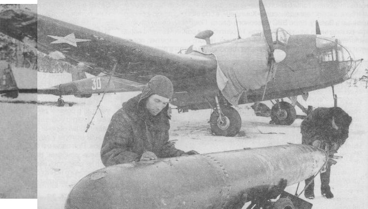
Авиация и Космонавтика 1996-04 / В.Котельников, А.Артемьев - Минно-торпедная: авиация особого рода
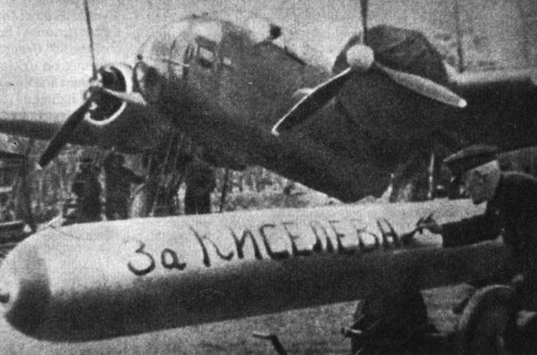
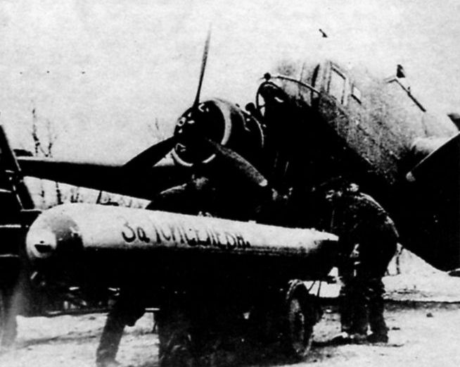
Торпеду Mk XII готовят к подвеске на "Хэмпден" TB1. 24-й мтап, Северный флот. Конец 1942 года.
Английские "Хэмпдены" оказались плохо приспособлены для эксплуатации в суровых условиях Заполярья, а с учетом неважных пилотажных характеристик, оценивались пилотами советской минно-торпедной авиации существенно ниже отечественных Ил-4.
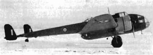
One of the 23 Hampden TB Mk Is that passed into service with the Soviet Navy’s air arm in 1942. -

Air International 1985-08
This photograph shows a Hampden in service with 24 PLMT in the Soviet Union. The inscription on the torpedo reads "For Kisyelev".
-

АвиаМастер 2002-07 / А.Овчаренко, С.Богатырев - "Огненные тараны" на море: легенды и факты /На фронтах Великой Отечественной/
25 апреля 1943 года в атаке на немецкий конвой геройски погиб экипаж торпедоносца "Хэмпден" под командованием капитана В.Н.Киселева. В ряде изданий указывается, что летчики совершили "огненный таран", потопив немецкий транспорт "Леезее". По другим, более достоверным данным транспорт был потоплен торпедой.
-

Мир Авиации 1995-01 / В.Котельников, Ю.Рыбин - "Балалайка" /В строю советских ВВС/
Подвеска торпеды под один из самолетов 24-го мтап, май 1943г.
-

Мир Авиации 1995-01 / В.Котельников, Ю.Рыбин - "Балалайка" /В строю советских ВВС/
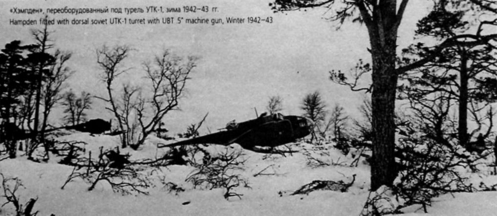
"Хэмпден", переоборудованный под турель УТК-1, зима 1942-43гг.
-

-

Мир Авиации 1995-01 / В.Котельников, Ю.Рыбин - "Балалайка" /В строю советских ВВС/
Гвардии капитан А.Стоянов в кабине своего самолета.
-
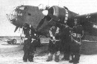
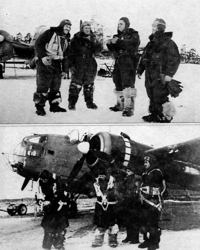
Моделист-Конструктор Морские самолеты палубного и берегового базирования Второй мировой войны / В.Котельников - Морские самолеты палубного и берегового базирования 1939-1945 /Самолеты Второй Мировой войны/ (5)
Экипаж командира 2-й эскадрильи 24-го МТАП ВВС СФ А.З.Стоянова перед боевым вылетом у своего "Хэмпдена", аэродром Ваенга (под Мурманском). 1942г.
-

Мир Авиации 1995-01 / В.Котельников, Ю.Рыбин - "Балалайка" /В строю советских ВВС/
А.Стоянов (первый слева, на фото снизу - первый справа) со своим экипажем: к-н Коровинский (штурман), с-т Ковтун (стрелок), ст.с-т Зайцев (радист).
-

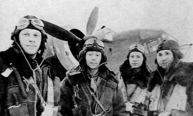
Мир Авиации 1995-01 / В.Котельников, Ю.Рыбин - "Балалайка" /В строю советских ВВС/
Экипаж, одержавший первую победу на английском торпедоносце. Капитан С.Трунов (первый слева) со своим экипажем: ст.с-т Черных (штурман), с-т Камнин, с-т Гортованный.
-

-

-


-

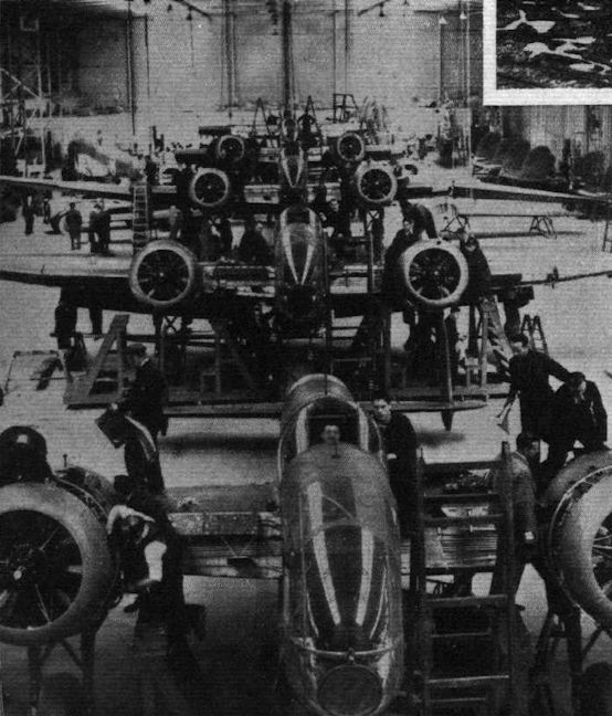
Flight 1939-05 / Flight
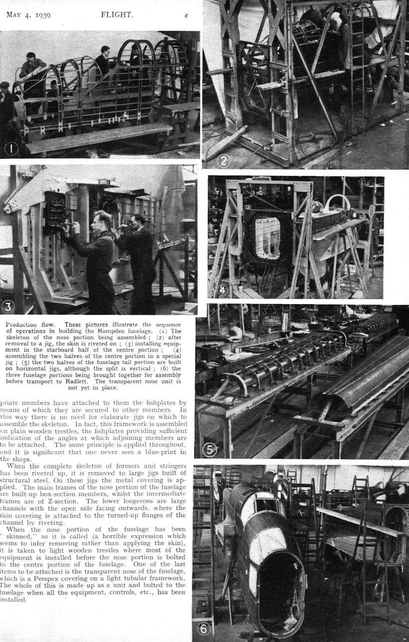
Production flow. These pictures illustrate the sequence of operations in building the Hampden fuselage. (1) The skeleton of the nose portion being assembled ; (2) after removal to a jig, the skin is riveted on; (3) installing equipment in the starboard half of the centre portion; (4) assembling the two halves of the centre portion in a special jig; (5) the two halves of the fuselage tail portion are built on horizontal jigs, although the split is vertical; (6) the three fuselage portions being brought together for assembly before transport to Radlett. The transparent nose unit is not yet in place.
-

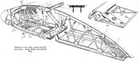
Flight 1939-05 / Flight
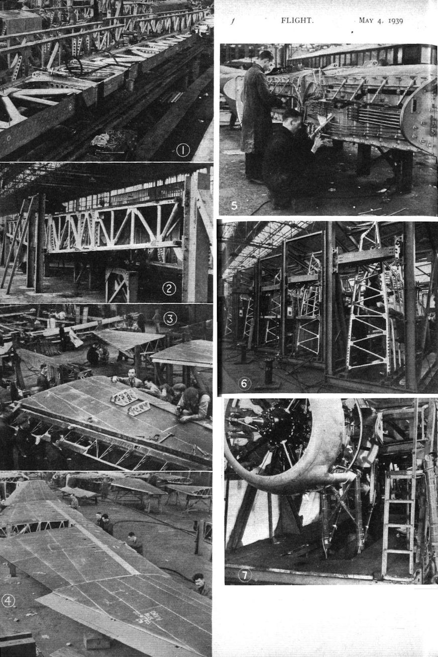
Growing wings: (1) the Hampden main spar in a horizontal drilling jig; (2) the spar in the assembly jig, where it forms the basis of the whole centre-section; (3) an outer wing having covering finished and ailerons attached; (4) assembling centre and outer wing portions before dismantling them for transport to Radlett; (5) installing leads and engine controls on front wall of spar box; (6) assembling trailing-edge portions in their jigs; (7) the engine installation jigs also have provision for assembling the undercarriage fully extended.
-

Flight 1939-05 / Flight Advertisements
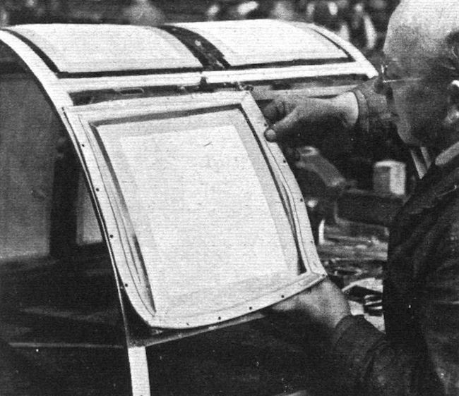
INSTALLING “LINATEX” KNOCK-OUT WINDOWS ON THE HAMPDEN.
-

Flight 1939-05 / Flight
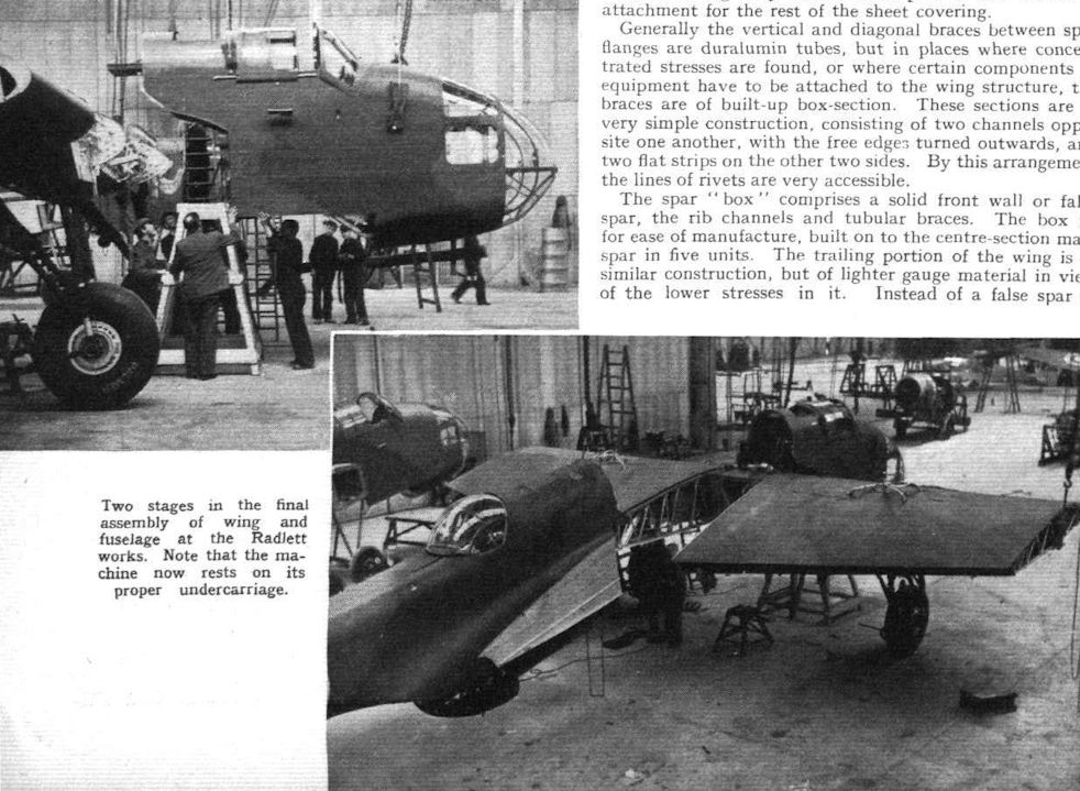
Two stages in the final assembly of wing and fuselage at the Radlett works. Note that the machine now rests on its proper undercarriage.
Hampdens under construction at Radlett in April 1939. -

Aviation Historian 25 / G.Baughen - The case for appeasement?
In the wake of the Munich Agreement production of bombers for the RAF was ramped up. One of the more promising new designs was the Handley Page Hampden, which was fast, manoeuvrable and could carry a bomb-load of 4,000lb (1,825kg). The Hampden bore the brunt of Bomber Command’s early wartime raids over Germany.
-

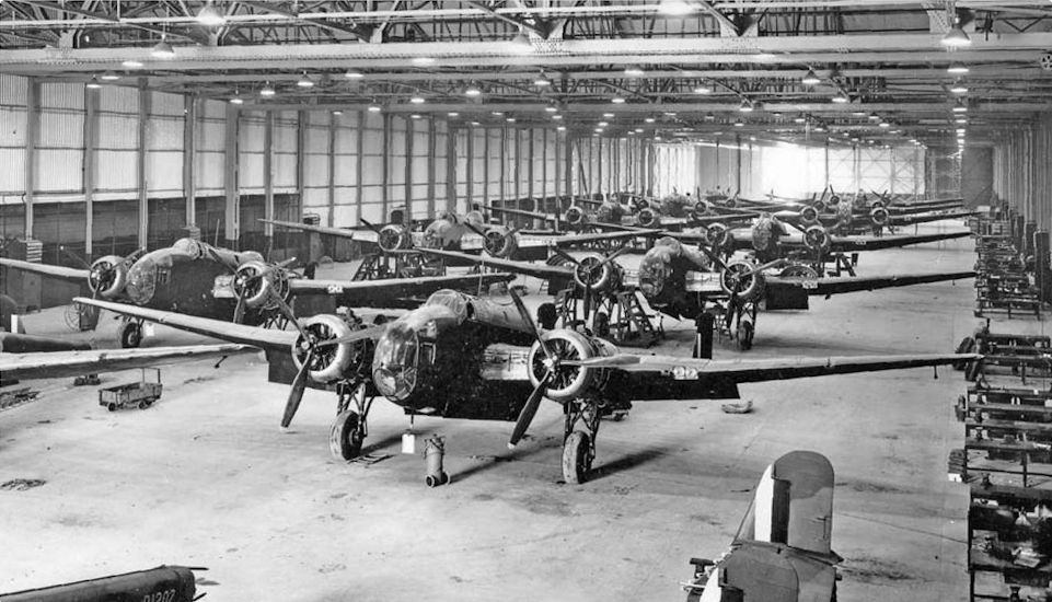
Flight 1939-05 / Flight
Bomber production: H.P. Hampdens, capable of 265 m.p.h., seen in the final assembly stage at the assembly plant at Radlett. The Hampden has two Bristol Pegasus XVIII engines with two-speed superchargers.
-

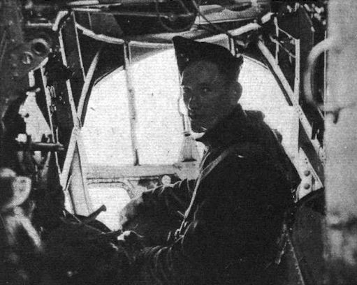
Air Enthusiast 1971-09 / H.Taylor - Flying the "Flying Suitcase" /Viewed from the Cockpit/
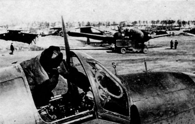
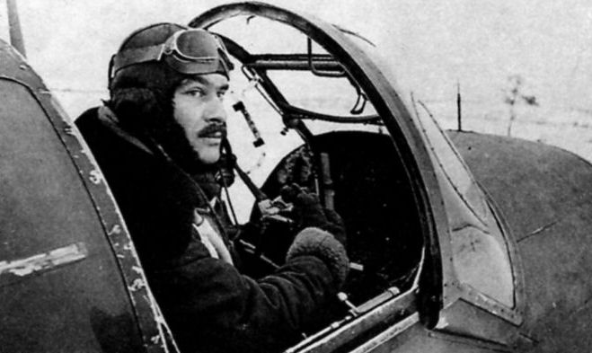
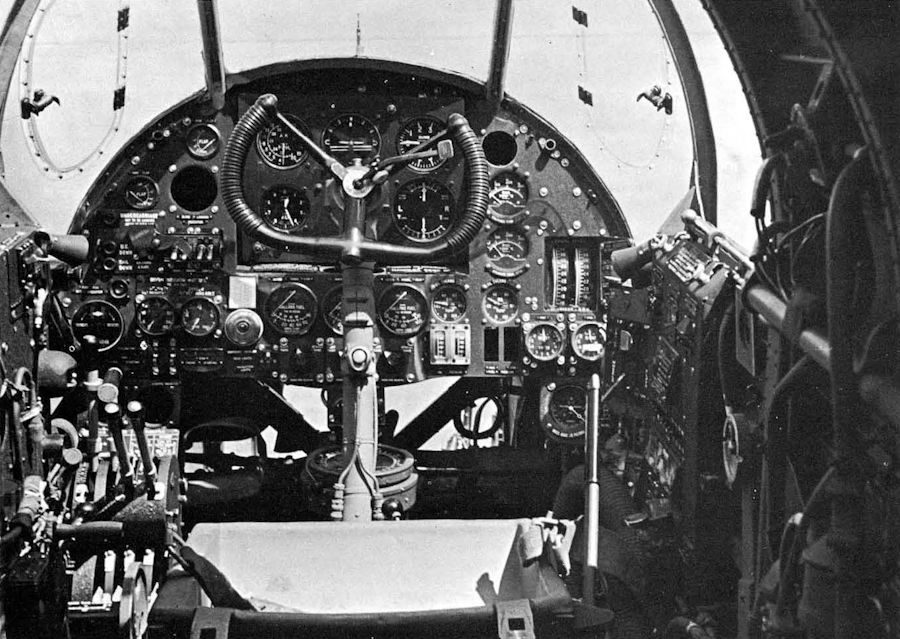
Кабина Hampden с плоским лобовым остеклением и одним неподвижным пулеметом Browning по левому борту скорее напоминает кабину одноместного истребителя, а не среднего бомбардировщика.
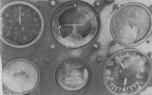
The cockpit of the Hampden was "cramped and cluttered’’, says the author of this article, but was well positioned to afford the pilot a view from wing-tip to wing-tip. This illustration clearly shows how the control column (with gun-firing button below the three-quarter wheel) obscured the directional gyro on the standard blind-flying panel, as well as one of the fuel gauges and the compass, on the floor. -

Aeroplane Monthly 1989-11 / I.Masson - Tinfish Hampdens
Interiors which give some idea ot the extensive equipment. The pilot’s cockpit with dashboard and controls.
-

Aeroplane Monthly 1976-12 / ??? - Helpless Hampden
A Hampden cockpit, with the blind flying panel visible directly behind the control column.
-

Flight 1939-06 / Flight
INDOOR PHOTOGRAPHY: Some interesting close-ups secured recently by a Flight photographer: Hampden pilot
-

Aeroplane Monthly 1976-12 / ??? - Helpless Hampden
Регистрационный номер: AE436 [3] AE436’s standard blind flying panel
-

Air Enthusiast 1972-11 / L.Coombs - Front-office evolution (3)
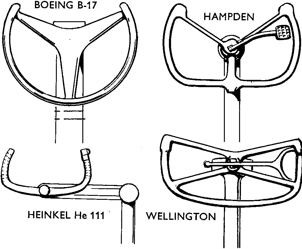
Sketches of four control columns of the World War II period which were typical of the practice adopted by three of the major combatant powers.
Другие самолёты на фотографии: Boeing B-17E / B-17G Flying Fortress - США - 1941Heinkel He-111P/H - Германия - 1938Vickers Wellington / Type 271 - Великобритания - 1936
-

Aeroplane Monthly 1989-11 / I.Masson - Tinfish Hampdens
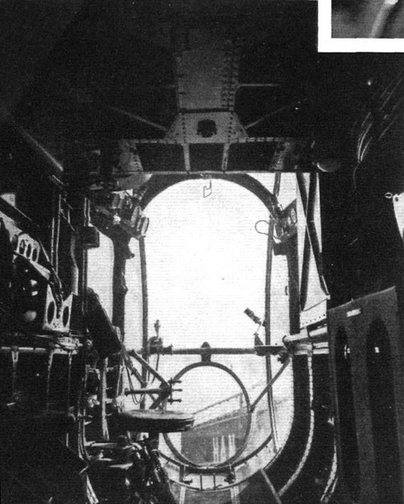
The original caption to this posed 1940 picture reads, “The navigator/bomb aimer makes an observation through the transparent nose of a Hampden”. Stirring stuff. However, the aircraft’s unusually narrow fuselage did provide better visibility for pilot and crew than in most other bombers.
-

Flight 1939-05 / Flight
The compartment of the front lower gunner and bomber, in the nose of the fuselage
-

Flight 1939-05 / Flight
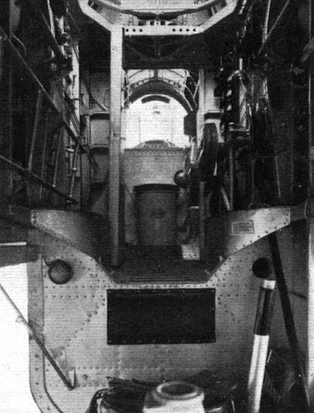
Interiors which give some idea ot the extensive equipment. A view looking forward from the lower aft gun position. The top gunner’s swivelling seat can be seen on the right.
-

Flight 1939-05 / Flight
There are two rear gun positions in the Hampden, an upper and a lower.
-

Flight 1939-06 / Flight
INDOOR PHOTOGRAPHY: Some interesting close-ups secured recently by a Flight photographer: Hampden wireless operator (photo was taken in the air)


-

Aeroplane Monthly 1994-11 / M.Oakey - Grapevine
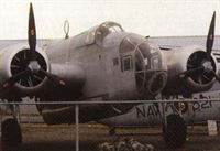
Регистрационный номер: P5436 [7] The Canadian Museum of Flight and Transportation’s Handley Page Hampden P5436 is nearing completion of its static restoration.
-

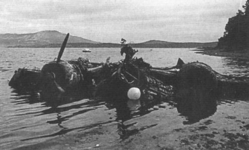
Aeroplane Monthly 1986-09 / Grapevine
Регистрационный номер: P5436 [7] Handley Page Hampden P5436 beached at Vancouver Island, British Columbia on June 22, 1986.
-

Aeroplane Monthly 1987-02 / M.Oakey - Grapevine
Регистрационный номер: P5436 [7] An enormous restoration task: the remains of Handley Page Hampden P5436 laid out at the CMFT's storage site at Surrey, British Columbia, Canada.
-

Aeroplane Monthly 1989-04 / M.Oakey - Grapevine
Регистрационный номер: AE436 [3] Remains of the centre section and tail of Handley Page Hampden AE436 arrived at the Lincolnshire Aviation Heritage Centre at East Kirkby on January 16, 1989. Donated by the Swedish Flygvapen Museum, they will eventually be incorporated into Brian Nicholls’ static restoration project. The Firestreak missile is not an original fitting.
-

Aeroplane Monthly 1991-10 / M.Oakey - Grapevine
The remains of a Handley Page Hampden from Russia at Rotterdam on August 13, 1991, awaiting removal to the UK. In this view the port wing (visible at lower left) has just been separated from the fuselage, on which an RAF roundel may still be discerned.
-
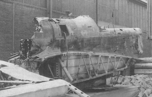
Aeroplane Monthly 1992-01 / M.Oakey - Grapevine
Регистрационный номер: P1344 [3] Detail views of Hampden P1344's fuselage taken on October 22, 1991.
-

Aeroplane Monthly 1992-01 / M.Oakey - Grapevine
Регистрационный номер: P1344 [3] P1344 propped together for inspection by its prospective new owners on September 14, 1991.
-
Aeroplane Monthly 1992-01 / M.Oakey - Grapevine
Регистрационный номер: P1344 [3] Handley Page Hampden P1344, recovered from Russia and laid out for inspection at its secret UK location in September 1991.
-

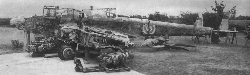
Aeroplane Monthly 1988-08 / M.Oakey - Grapevine
Регистрационный номер: P5436 [7] Dramatic proof that Grapevine parts-requests bring results: Handley Page Hampden P5436, under static restoration by the Canadian Museum of Flight and Transportation (CMFT) in British Columbia, now has a nose section following a plea published in our February 1987 issue. Sheffield reader and restorer Alan Downing saw the request and remembered that the Warplane Wreck Recovery Group at High Ercall had a nose section on loan from the Cosford Aerospace Museum. He sent a photo of it to his contacts at the CMFT and thus set the ball rolling: the nose section arrived there on May 24, 1988. The Hampden, pulled out of the sea off Vancouver Island 2yr ago, is the world’s sole substantially complete example.
-

Aeroplane Monthly 1989-11 / M.Oakey - Grapevine
Регистрационный номер: P5436 [7] The newly-completed nose section of Canadian Museum of Flight Handley Page Hampden P5436 on display with the aircraft's yet-to-be-restored sections at Surrey, BC on June 18, 1989. This picture gives a graphic impression of a new Hampden rising from a pile of wreckage.
-

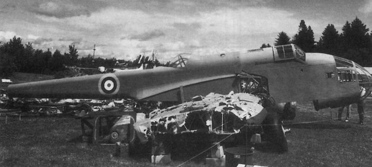
Aeroplane Monthly 1990-08 / M.Oakey - Grapevine
Регистрационный номер: P5436 [7] The unmistakable tadpole profile of a pristine Handley Page Hampden emerges from a pile of corroded wreckage at Surrey, British Columbia, where the Canadian Museum of Flight and Transportation is continuing to rebuild Hampden I P5436. The aircraft was recovered from the sea off Vancouver Island 4yr ago.


-

Aeroplane Monthly 1989-11 / I.Masson - Tinfish Hampdens
Регистрационный номер: L4105 [4] Flak damage to the tail of Hampden L4105. Close inspection reveals how the distorted tailplane is fouling the base of the port rudder.
-

Aeroplane Monthly 1989-11 / I.Masson - Tinfish Hampdens
Регистрационный номер: L4105 [4] Hampden L4105 photographed following a crash landing at RAF Leuchars on August 2, 1943. The aircraft was struck off RAF charge in December the same year.
-
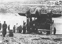
Aeroplane Monthly 1986-06 / R.Nesbit - Arctic Venture (5)
A Hampden being transported on a ferry barge near Vadso in northern Norway in 1942, date unknown. The pilot must have made a good emergency landing, for there appears to be little damage. The aircraft is probably a Hampden of 144 or 455 (RAAF) Squadron, several of which were bst when flying to Russia on September 4-5, 1942.
-

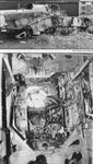
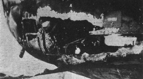
Flight 1940-10 / Flight
The burnt-out rear lower gun turret and bomb bay of the Handley Page Hampden on which Sgt. Hannah was flying when he earned the V.C.
-
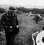
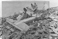
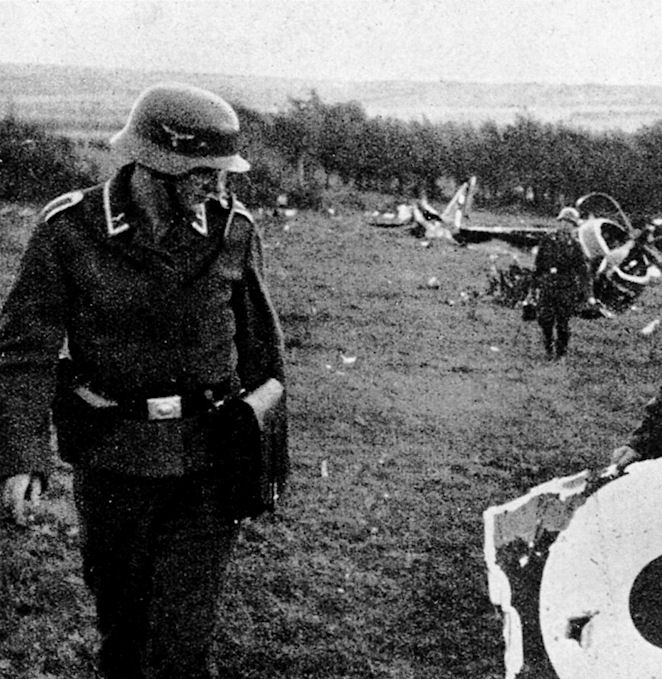
Мировая Авиация 117
Немецкие солдаты осматривают обломки Hampden, осень 1940 года. В силу небольшого опыта экипажей первые ночные налеты приносили минимальные результаты, но поддержали моральный дух англичан.
-
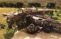
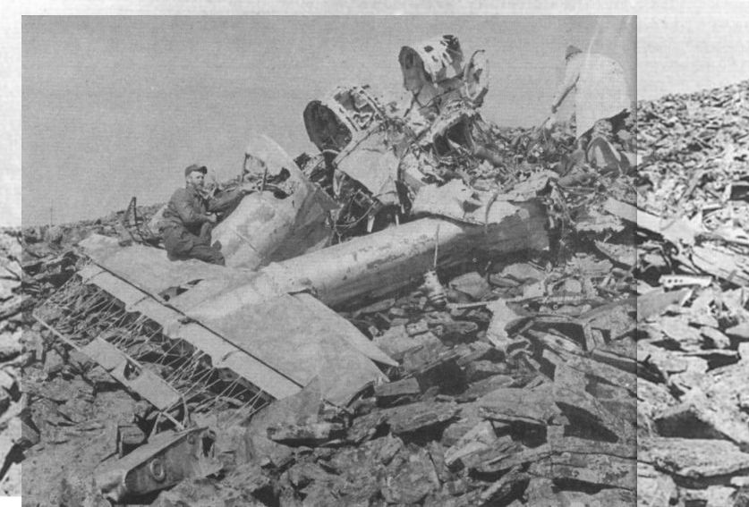
Aeroplane Monthly 1986-06 / R.Nesbit - Arctic Venture (5)
Регистрационный номер: AE436 [3] The main wreckage of AE436, with the tail boom and tailplane in front of the forward fuselage, from which two escaped alive.
Part of Hampden AE436 of 144 Squadron, discovered in August 1976 on the side of the remote Tsatsa mountain in Sweden, where it crashed on the night of September 4-5, 1942 en route from Sumburgh to Afrikanda in Northern Russia. The pilot, Pit Off D. I. Evans, and a passenger, Cpl B. J. Sowerby, survived; the other three crew members were killed. -

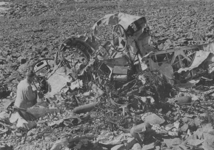
Aeroplane Monthly 1976-12 / ??? - Helpless Hampden
A port three-quarter rear view of the wreckage, with twin Vickers K guns just visible in the foreground.
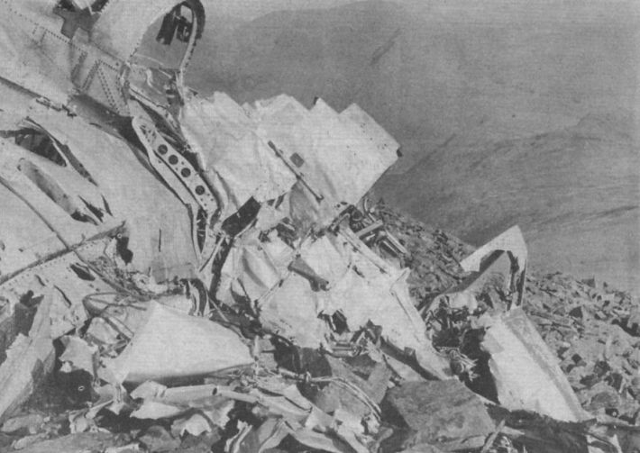
-

Aeroplane Monthly 1976-12 / ??? - Helpless Hampden
Looking along the starboard wing leading edge at the cockpit section.
-

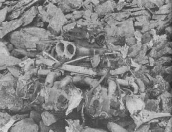
Aeroplane Monthly 1976-12 / ??? - Helpless Hampden
One of the Hampden’s 980 h.p. Bristol Pegasus VIII radial engines, which was lying within 20 yards of the fuselage.


-

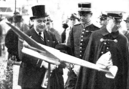
Flight 1936-05 / Flight
The Swedish Minister of Defence, Herr Wennerstrom, and Swedish Army officers inspect the model of the H.P.53.
-
-

-

-

-
-

-

Flight 1940-05 / Flight Advertisements
Handley Page leading edge slots and slotted flaps enable full control to be maintained throughout the speed range, thus permitting the Hampden to be landed in confined spaces, a feature of paramount importance in war operations.
-
Aeroplane Monthly 1988-07
First flight of the Handley Page Hampden: June 21, 1936
-

Aeroplane Monthly 1988-12 / P.Masefield - Wren
Rhe first Wren Oddentification featured the Handley Page Hampden and was first published in the March 14, 1941, issue of The Aeroplane.
-
-
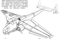
Flight 1939-05 / Flight
‘Split’ construction is a production feature. This sketch shows the main units into which the structure is divided. The middle and tail portions are split vertically into port and starboard halves.
-

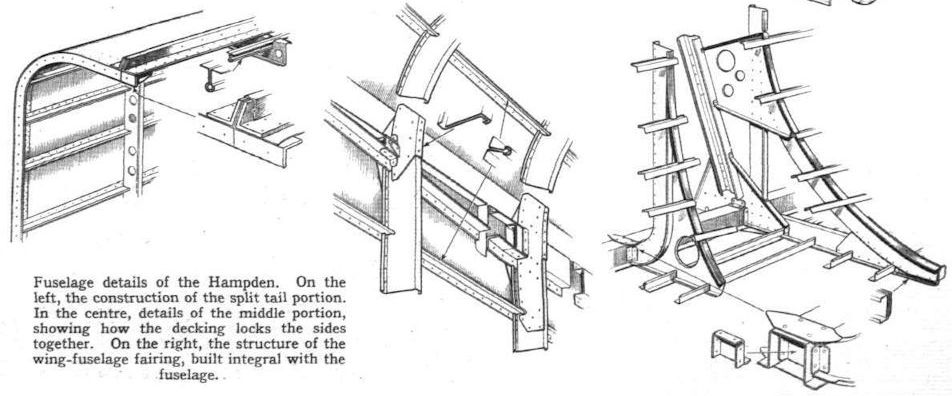
Flight 1939-05 / Flight
Fuselage details of the Hampden. On the left, the construction of the split tail portion. In the centre, details of the middle portion, showing how the decking locks the sides together. On the right, the structure of the wing-fuselage fairing, built integral with the fuselage.
-
Flight 1939-05 / Flight
Details of the wing centre-section structure. Inset shows the slotted flap.
The wing of the Hampden is also of single-spar type, but has a girder spar. The false front spar serves mainly as a support for the leading-edge unit. -

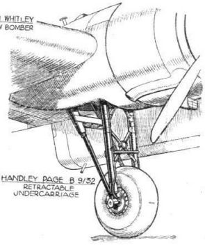
Flight 1936-07 / Flight
Handley Page B 9/32. Retractable undercarriage
-

Flight 1940-12 / Flight
Comparative pictures by "J.P." of ten twin tails, all from the same angle: The twin arrangement of fins and rudders has advantages from both aerodynamical and military aspects. It gives the rear gunner an excellent field of fire, especially if the turret is placed fairly far aft. Smaller control areas can be used and, since these surfaces are in the airscrew slipstream, good control is obtained at low speeds.
Другие самолёты на фотографии: Armstrong Whitworth Whitley / A.W.38 - Великобритания - 1936Blohm und Voss Ha.139 - Германия - 1936Breda Ba.88 Lince - Италия - 1936De Havilland Flamingo / D.H.95 - Великобритания - 1938Dornier Do.17Z / Do.215 - Германия - 1939FIAT BR.20 Cicogna - Италия - 1936Junkers Ju.86 - Германия - 1934Lockheed Hudson A-28 / A-29 - США - 1938Messerschmitt Bf.110 - Германия - 1936
-
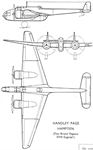
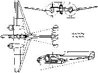
Flight 1939-05 / Flight
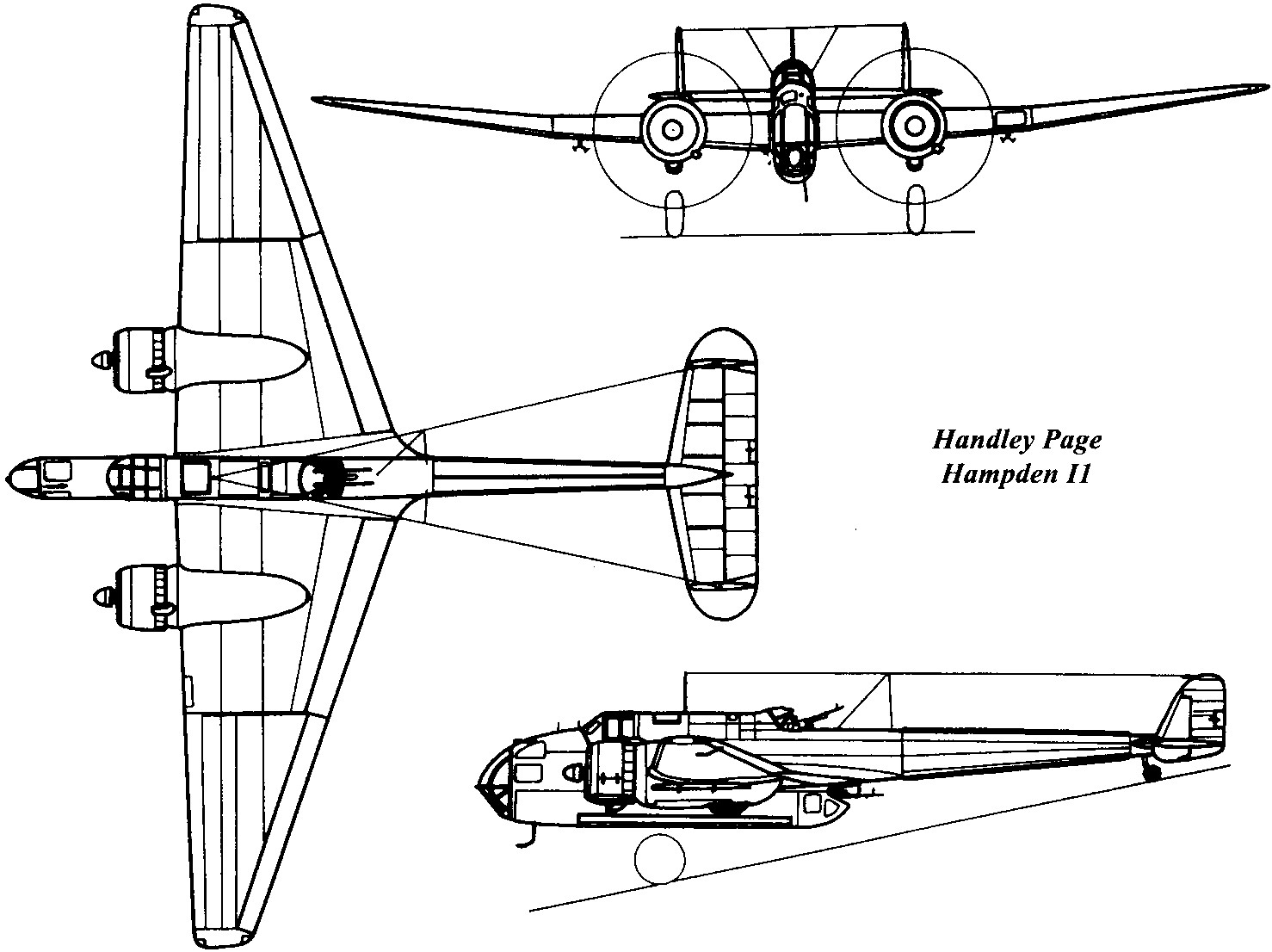
Handley Page Hampden (Two Bristol Pegasus XVIII Engines)
-
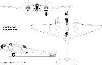
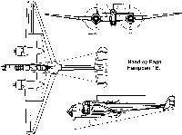
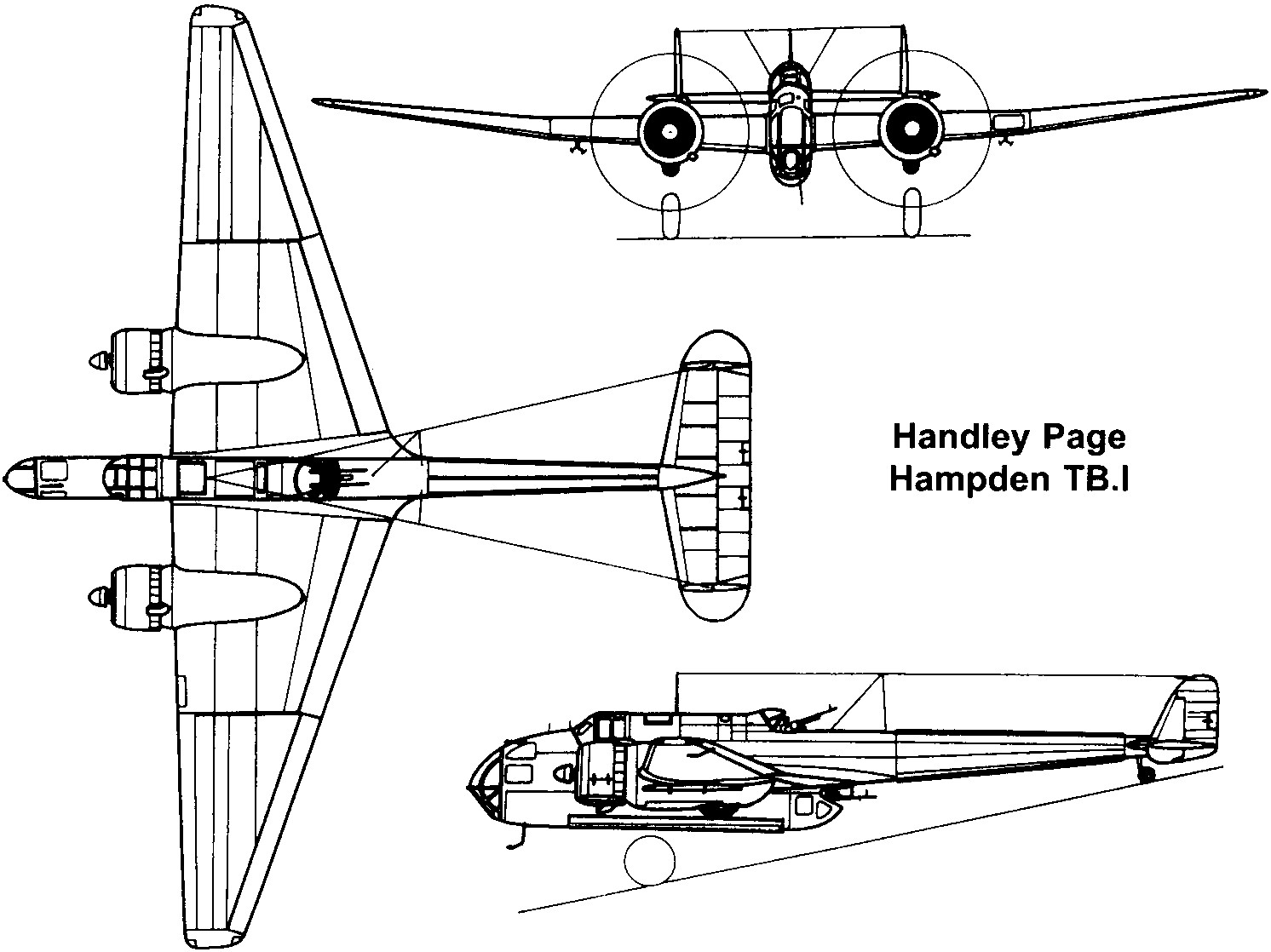
Мировая Авиация 149
Handley Page Hampden Mk I
-
-
-
-
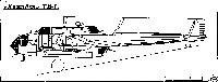
Air Enthusiast 1971-09 / H.Taylor - Flying the "Flying Suitcase" /Viewed from the Cockpit/
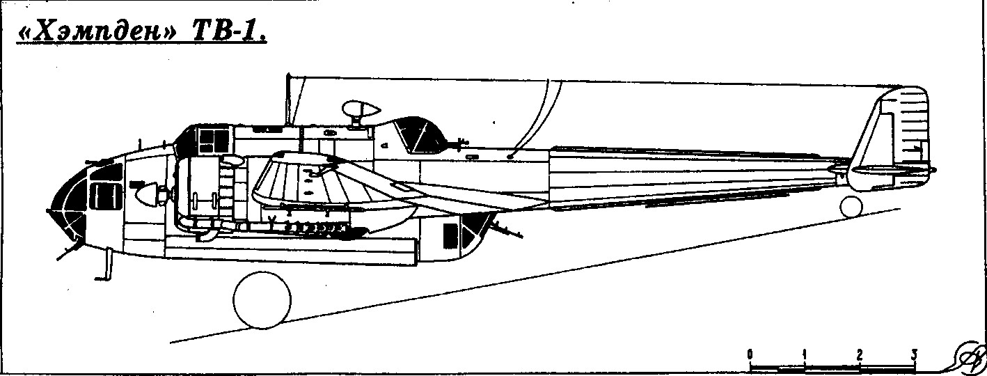
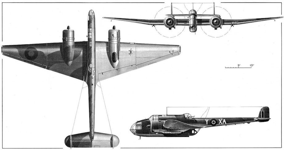
A Hampden TB Mk I torpedo-bomber (with enlarged bomb-bay) in the markings of No 489 Squadron, a New Zealand unit serving with the RAF.


Тип фотографий
- Все фото (205)
- Боковые проекции (11)
- Цветные фото (2)
- Ч/б фото (139)
- Кабина (11)
- Реставрация (11)
- Обломки (9)
- Модели, рисунки, схемы, чертежи (22)